[Trade Journal]
Publication: Electrical World and Engineer
New York, NY, United States
vol. 42, no. 24, p. 957-960, col. 1-2
Montreal, the Greatest Centre of Transmitted Power.II.
By Alton D. ADAMS.
SUB-STATION WORK.
AT the McCord Street sub-station the 4,000-volt, three-phase, 63-cycle current from the plant at Lachine Rapids is transformed for distribution to 2,400 volts. This transformation is effected by means of twelve transformers of 250 kw each, and four transformers rated at 1,000 kw each. The combined capacity of these transformers is thus 7,000 kw. The four transformers of 1,000 kw each are connected so as to change the current from three-phase on the primary coils to two-phase on the secondary coils.
| |||
| Fig. 9.Distribution Board at Shawinigan Sub-Station. |
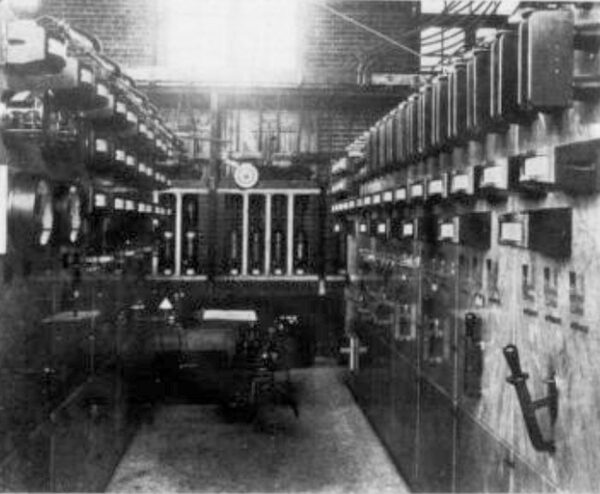
At the Shawinigan sub-station in Maisonneuve, a suberb [sic] suburb of Montreal, but not within the city limits, the three-phase circuit of three aluminum conductors delivers current at about 44,000 volts and 30 cycles. The generating plant at Shawinigan Falls, on the St. Maurice River, already described in these pages, delivers current to the transmission line at approximately 50,000 volts, but the loss in conductors reduces the terminal pressure to about that just stated for the substation. Each of the three conductors of the transmission line, after entering the sub-station, is connected to a series of 44 lightning arresters with six air-gaps each, giving 264 air-gaps between each line and the ground. Between the connection to lightning arresters and the connection to transformers two static interrupters are connected to each of the three high-tension wires. Each of these interrupters is single-pole, and rated at 50,000 volts, 26 amp., and 2,600 alternations per minute. From the interrupters the 44,000-volt circuit passes to five oil-cooled transformers, which are rated individually at 1,000 kw, with current at 30 cycles, and at 2,000 kw with current at 60 cycles per second. By these transformers the three-phase current is reduced from 44,000 to 2,400 volts, and then passes to five motor-generators that change the frequency from 30 to 63 cycles per second. As at first installed, two of these motor-generators delivered three-phase current at 63 cycles and 2,400 volts, and three of the motor-generators delivered two-phase current of the same frequency and voltage. It is the intention, however, to change two of the motor-generators so that the entire five will generate two-phase current. From these motor-generators the 2,400-volt, 63-cycle current passes to a switchboard in another part of the sub-station, and is thence distributed in part directly to customers of the Montreal Light, Heat & Power Company, and in part by passing through the central sub-station of that company. Under a 50-year contract between the Shawinigan Water & Power Company and the Montreal Light, Heat & Power Company all of the energy delivered by the former is received by the Montreal electrical supply system save that a short local railway has the right to use a maximum of 250 hp. The switch-board installed by the Montreal Light, Heat & Power Company is provided with motor-driven and manual oil switches that connect the 2,400-volt, 63-cycle bus-bars with the various service feeders. This switchboard is also provided with indicating volt and ampere-meters and recording wattmeters. The five 1,000-kw, 30-cycle, oil-cooled transformers, already mentioned, that reduce the transmitted energy from 44,000 to 2,400 volts pressure are worthy of note for their large dimensions. The tank of boiler iron, filled with oil, that contains each of these transformers, is cylindrical in form, 15 ft. high, 7-1/2 ft. in diameter, and contains 750 gallons of petroleum. Each of the five motor-generators that receive the current from these transformers is made up of three complete machines, a 2,400-volt, 30-cycle, three-phase, synchronous motor, a 2,400-volt, 63-cycle, two or three-phase alternator, and a 125-volt, direct-current exciter of 583-amp. capacity. These three machines are direct-connected and operate at the common speed of 450 r.p.m. The motor and alternator are both of the type with internal revolving magnets, and stationary armature coils. A solid coupling unites the shafts of the motor and alternator and the extended shaft of the latter carries the armature of the exciter. The exciter magnet frame is mounted on a solid extension of the alternator base. To secure alignment of the motor and alternator in each unit their bases are bolted to four 15-in. I-beams that are embedded in the concrete foundation. Each I-beam is 25 ft. long. The extreme width of each motor and alternator base is 11 ft. 2 in. From the bottom of the I-beams to the top of the motor frame the distance is 9 ft. 5% in. Over the three machines that make up each motor-generator unit the extreme length parallel to the shaft is 29 ft. 55/16 in. Each direct-current exciter furnishes current to the magnet coils of both the motor and alternator to which it is mechanically connected. In the sub-station with the five motor-generators just considered there is a smaller motor-generator made up of a 100-hp, 30-cycle, three-phase, 2,300-volt motor, direct-connected to an 85-kw, 125-volt generator. Current for this 100-hp motor is taken directly from the secondary side of the static transformers. When one of the large motor-generators is to be started, each of which is rated at 800 kw, the 85-kw generator is driven by the 100-hp motor, taking current from the secondaries of the static transformers, and the 125-volt direct current thus obtained is used to operate the exciter of the large motor-generator as a motor. As soon as the large motor-generator reaches its synchronous speed its motor is connected to the transformers that deliver energy from Shawinigan Falls, and the 85-kw dynamo is disconnected.
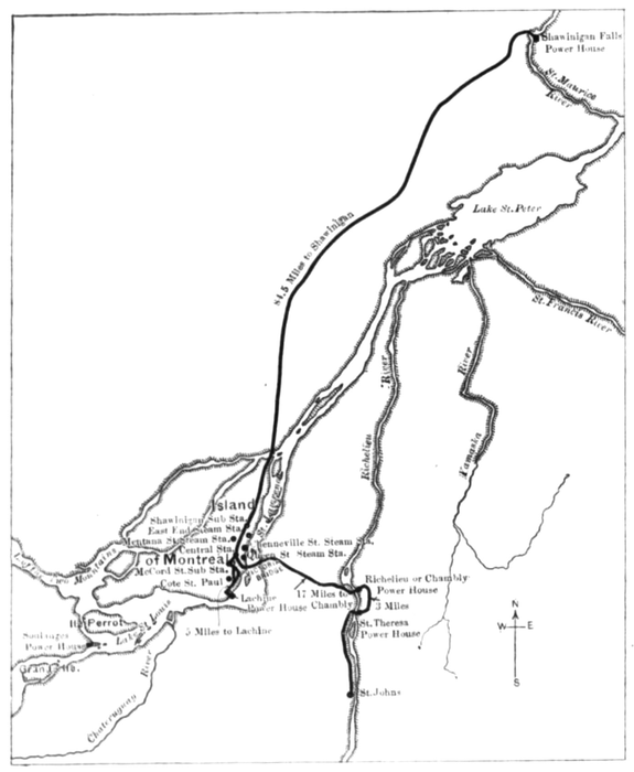 |
| Fig. 10 Map Showing Location of Water Power Plants and Distributing Stations. |
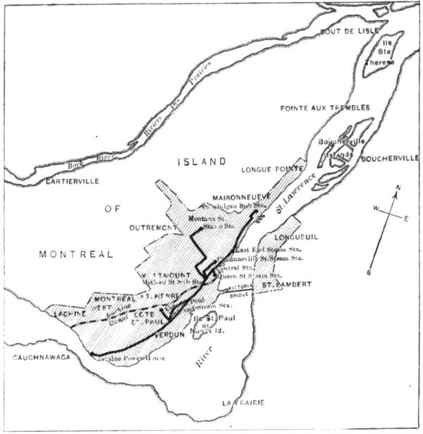 |
| Fig. 11. -- Map Showing Location Sub-Stations and the District of Covered by the Service |
The building for the Shawinigan sub-station is of brick, one story high, with a roof supported on steel trusses, and a concrete floor. Internally the main building is divided into two parts by a brick wall parallel to its longer sides. In one of the two rooms thus formed the five 1,000-kw transformers are located, and in the other room are the motor-generators. On the ground the main building measures approximately 95 by 115 ft. A one-story brick wing at one side of the main Shawinigan sub-station contains the switchboard equipments through which energy is delivered to the lines of the electrical supply system.
THE CENTRAL SUB-STATION.
The central sub-station located in the block bounded by Ottawa, Wellington, Prince and Queen Streets is the largest and most important connected with the Montreal system of electrical distribution. To this sub-station come the high-tension transmission lines from the water power plants at Lachine Rapids, Chambly, while the Shawinigan system is also connected through the 2,300-volt feeders that come from the Shawinigan sub-station. Energy at 2,000 volts, 63 cycles two-phase from the McCord Street Station, and at 22,000 volts, 63 cycles, three-phase from Chambly, is transformed at the central sub-station to current at 2,300 volts, 63 cycles, two-phase, for general distribution. Ultimately, the equipment of main transformers at the central sub-station will comprise sixteen units of 2,750 kw each, and of these units ten are already installed, giving a present capacity of 27,500 kw. These transformers are of the air blast type, and were made by the Westinghouse Electric Manufacturing Company. Besides these main transformers receiving energy direct from the transmission lines, the central sub-station contains thirty transformers of 60 kw capacity each, for the operation of enclosed, alternating arc lamps in series for street lighting. Each of these transformers with its regulator delivers a constant, alternating current of 7.5 amp. and a maximum pressure of 4,000 volts. These constant-current transformers, which take energy from the main transformers at 2,400 volts and deliver it at any desired voltage up to 4,000, were made by the Western Electric Company.
Current for the 250 and 500-volt, three-wire system, which operates direct-current motors, is supplied by two motor generators at the central sub-station. Each of these motor generators is made up of a 300 kw, 2,400-volt, two-phase synchronous motor, and a 250 kw, 250-volt, direct-current generator. These two synchronous motors draw their energy from the main transformers. To maintain the pressure in the air chamber beneath the air-blast transformers, space has been provided on the main floor of the sub-station for four blower units, and three of these units are in position. Each blower unit is made up of one 40 hp, 550-volt, two-phase induction motor, of Westinghouse make, with a centrifugal blower with a 32-inch circular opening on each end of its shaft. These blowers were made by the Sturtevant Company, and are intended to maintain a pressure of 1.8 inches of water per square inch.
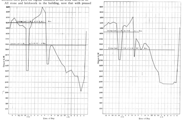 |
| Figs. 12 and 13.Output Curves. |
Provision is also made on the main floor for two motor-driven ex-citers to furnish direct-current to the magnets of the large machines, and also for an emergency set consisting of a 300 kw, 2,400-volt, two-phase synchronous motor direct-connected to an alternator of equal capacity. All of the transforming and converting apparatus just named occupies a central position on the main floor of the sub-station, save the constant-current transformers. Ranged about three sides of the sub-station in galleries and on one side at the main floor level are the high and low-tension switchboards that receive, control and dis-tribute the energy from the water power plants. In the gallery on one of these three sides are the marble and soapstone compartments that contain the knife switches for the high-tension lines from the water power plants. From these switches the 22,000-volt, three-phase circuits pass to the primary coils of the main transformers. The secondary, 2,400-volt circuits from these same transformers go to the transformer panels and distributing board in the gallery on another side of the sub-station, by the way of manually operated oil switches located in the same gallery. The gallery on a third side contains another portion of the distributing switchboard. Beneath the gallery on one side of the sub-station are the thirty constant-current transformers already mentioned, on the main floor. An arc lamp switchboard, connecting these transformers with the series circuits for street lighting, separates the space beneath the gallery last named from the central portion of the main floor, where the large transformers, motors and motor-generators are located. This arc switchboard is the only one on the main floor level. The fourth side or front of the sub-station, where the large, main entrance is located, is free from electrical apparatus, and starting from this side a traveling crane sweeps the entire central space of the main floor. This crane is driven by electric motors, and has a capacity of 30,000 pounds. It was built by the Niles Company.
The building of the central sub-station is one of the largest and best to be found anywhere for this purpose. Because of the high voltage and great amount of energy entering this sub-station, and its importance in the Montreal electrical supply system, it was located in about the center of a city block, so that a large, clear space was left between each of its outside walls and the public street. The block of land in which the sub-station is located measures 195 ft. 4 inches wide on Ottawa Street, 238 ft. along Queen Street, at right angles to Ottawa Street, to Wellington Street, and 310 ft. 8 inches along Prince Street, parallel with Queen Street, to Wellington Street. In front the sub-station sets back 94 ft. from Ottawa Street; one side is 35 ft. 8 in. from Queen Street, another side is 56 ft. 8 in. from Prince Street, and the rear corner nearest to Wellington Street is 27.5 ft. therefrom. From the wall of the sub-station to the buildings on the opposite side of Queen Street is 73 ft. 10 in.; from the sub-station to the buildings on the opposite side of Prince Street is also 73 ft. 10 in., and the buildings nearest the rear corner on Wellington Street are 74 ft. distant. The vital importance of these figures may be appreciated from the fact that the central sub-stations is located in a solidly built business portion of the city. The sub-station building is one story high above the basement, nearly square in outline, of pleasing architecture, and as nearly fire-proof from foundation to roof as steel and masonry can make it.
Inside the central sub-station at the main floor level the dimensions are 118 ft. by 122.5 ft., and from main floor to the lower cord of the steel roof trusses is 34.5 ft. The lowest part of the roof outside is 41 ft. above the main floor. At an elevation of 10 ft. above the main floor is the switchboard gallery that has been previously mentioned, which extends around three sides of the building. Another gallery 14.5 ft. above that just named, and located on parts of two sides of the sub-station, gives access to lightning arresters and knife switches on the distribution circuits. Beneath the entire main floor there is a basement paved with concrete 1 ft. thick. The surface of this concrete is 7 ft. 10'%4 in. below the main floor around the outer portion and 11 ft. below in the central portion of the building. In this central portion of the basement a space 37 ft. 8 in. by 65 ft. 2 in. is enclosed for an air pressure chamber by masonry walls each 2 ft. thick. On the main floor over this air chamber are set the sixteen 2,750-kw trans-formers and the four blower units. The floor space actually occupied by the group of transformers with an aggregate capacity of 44,000 kw is within 38 by 40 ft., and it may be doubted whether an equal capacity of transformers can be found within so small a space else-where. Beneath each transformer and each blower an opening in the main floor permits the movement of air out of or into the chamber. The air forced into the chamber by the blowers rises through the transformers and may escape through the windows in the side walls, or the skylight.
The sub-station receives daylight through high windows in each of its four sides, and through windows in the sides of the skylight which extends along the center of the roof between two opposite sides of the building. Light and ventilation for that part of the basement next to the outside walls is secured by small windows along the foundation wall and a little above the ground level. All windows about the sub-station are framed in channel, T or angle iron, and fitted with 3-in. wired plate glass. In its central portion the main floor of the sub-station was designed to support a superimposed load of 400 pounds per square foot, and along the sides beneath the galleries the design was for 70 pounds per square foot. Seventy pounds per square foot was the specification for the strength of all gallery floors. For the roof a safe capacity of 125 pounds per square foot was required. Structurally the sub-station is composed almost entirely of brick, tile, steel and stone. The stone foundation extends from 9 ft. 8 in. below to 5 ft. 3 in. above the ground line, and its footing 7.5 ft. wide rests on natural soil. Above this stone foundation the walls are of brick with heavy stone belt courses, plinth course, pier blocks, lintel, moulded course, pilasters and coping. At intervals along their out-sides, and at the corners the brick walls are reinforced by heavy piers. Between these piers the regular thickness of the brick wall is 21 in.
All stone and brickwork in the building, save that with pressed brick, was laid with a mortar composed of one part Portland cement and two parts sharp sand. Spaced along the brick walls of the sub-station with their footings in the stone foundation, and also along two sides of its central floor space, are a number of steel columns that support the I-beams for the main floor and the gallery floors, the traveling crane and also the steel roof trusses. The brick walls thus carry only their own weight. Under the central part of the main floor there are independent foundations that carry the heavy machinery there located. As a part of the steel columns is built into the brick walls, the stability of the latter as to any side strains is thereby greatly increased, the steel work being tied together from one side of the station to the other. Steel I-beams carried by the vertical columns and the central foundation walls and piers support the main floor of the sub-station. The first or lower gallery floors are also laid on I-beams secured to the vertical columns. In the second or upper gallery the floor is laid on heavy angle steel shapes that are carried with their supports by the columns in the brick walls. The framework of stairways leading from the basement to main floor, from the main floor to the first gallery, and so on up to the second gallery, and the roof is of iron and steel, and the treads are of slate. A framework for the sides and roof of the skylight is built up of angle steel and I-beams resting on the steel trusses carry the main roof. The main floor, that of the first gallery and the roof, are all built up of terracotta arches. On the second gallery the floor is laid with slate slabs. On the main and first gallery floors the tile arches are covered with a granolithic mixture of cement, sand and crushed granite 214 in. thick. Over the terracotta blocks and I-beams of the roof a coating of cement mortar at least 1/2 in. thick was laid to an even surface. On this surface there was placed a layer of boiling pitch, and then tarred felt roofing with another outside coating of the pitch. After this last was dry, boiling asphalt was spread over the roof to a depth of 3/4 in., and in this hot asphalt book tiles 1 in. were laid with 1/4-in. joints. The ceiling of the roof was plastered with a mortar composed of one part cement and two of sand, and then with cement and plaster of paris.
ECONOMIC ASPECTS.
The showing of 46 per cent. of the gross earnings as net income in the Montreal system, as above noted, has been made through good engineering. This will be appreciated from the fact that the regular rate for electric lighting in Montreal is 15 cents per kw-hour, while the rates to very large consumers like the cotton mills and the street railway compare favorably with the cost of steam power. Without neglecting the various other elements that affect the operative efficiency of a great system like that at Montreal, a special effort has there been made to reduce losses in distribution and build up a relatively large day load of motors. As has already been pointed out, the Royal Electric Company was the largest distributor of electrical energy in Montreal prior to the formation of the Montreal Light, Heat & Power Company, of which the former company is now one of the constituent units. In 1896 Mr. P. G. Gossler, at present general superintendent and engineer of the Montreal Company, occupied a like position with the Royal Company, and a paper presented by him at the annual convention of the Canadian Electrical Association, in that year, gives some interesting facts as to the methods followed to reduce distribution losses in the system of this latter company.
Among these facts the results of changes in the number and type of service transformers may be noted. The object in these changes was to displace smaller transformers by a less number of larger ones, and to supply consumers as far as practicable from secondary mains having approximately the lamp voltage. Following out this idea, reconstruction was begun on the alternating lighting service of the Royal Company, which included 1,160 transformers wired up to about 53,000 incandescent lamps. In the course of this reconstruction 473 of the old transformers were removed, 345 being replaced by new transformers, 18 taken down because the service was discontinued, and 110 disconnected because the customers served by them were connected to other old transformers nearby. Meantime 229 new transformers were connected to the lines, and of these 187 replaced old transformers, and 42 were used for new customers. These changes left 916 transformers wired up to 60,000 lamps. With the 1,160 transformers and 53,000 lamps on the lines during the year preceding this reconstruction the smallest load at the station was 380 amp. During ten months after the reconstruction the minimum load on the station with 916 transformers and 60,000 lamps connected to the lines was 245 amp., or 135 amp. less than that with the previous smaller number of lamps and larger number of transformers. This saving of 135 amp. in the minimum load was obviously due to less leakage of current through the new transformers than through the smaller ones that were removed. For the 229 new transformers the leakage current was 19 amp., from which it follows that the leakage of the 473 old transformers that were removed amounted to 135 + 19 = 154 amp. Of the total saving of 135 amp. in leakage current, 36 amp. was due to the removal of the 110 transformers whose lamps were connected to other old transformers through secondary distribution mains. From this it appears that by replacing 345 of the old by 187 new transformers a saving of 99 amp. in leakage current was effected. The entire cost of making the changes in the 187 transformers and the distribution lines, including the cost of the new transformers, amounted to $65 per transformer on an average after the value of the old transformers, as scrap, was deducted. It was computed that the saving in the cost of coal at $2.75 per ton amounted to $25.58 annually for each of the 187 transformers on an average, so that the reduction in the outlay for fuel alone would pay for the change in about 214 years. It was also computed that when the 1,160 old transformers have all been replaced by 636 new transformers the leakage current would be reduced to less than 75 amp. As the Montreal plant was operated 24 hours per day it was further estimated that the reduction of 135 amp. in the leakage current resulted in a yearly saving of $7,348 for coal at $2.75 per ton. Looking at the 135 amp. as capacity for an increase of load, it was said to correspond with 2,700 lamps of 16 cp in operation, or about 9,000 such lamps connected to the system.
Perhaps the most notable result in the operation of the distribution system at Montreal, as it stands to-day, is the great increase in the connected load of stationary motors, and the relation of this motor load to the maximum load at the station. These results are brought out clearly by the records of kilowatt outputs during a December day of 1900, and an April day of 1901, at the station of the Royal Electric Company. During the 24 hours of the December day the average load at this station was 66 per cent. of the maximum load, and during the 24 hours of the April day the average load was 65 per cent. of the maximum there. These exceptionally high average loads show at once the influence of the relatively great capacity of connected motors, but the mystery is how a day load of motors, however great, can bring the average so far up toward the maximum load. As is well known, a day load of motors operating from 7 A. M. to 6 P. M. laps well over onto the heavy lighting load during the late hours of each afternoon during the winter months, and thus presents a direct addition to the maximum station load. With the great motor load at Montreal it has been necessary to avoid the conjunction of the normal motor and the maximum lighting demands. That this result has been reached at Montreal may be gathered from the fact that the average load at the station of the Royal Electric Company from 7 A.M. to 6 P.M. was not only 85 per cent. of the maximum load during the April day, but was also 85 per cent. of the maximum on the December day, when the annual maximum of the lighting load would naturally be reached. The fact that the regular motor and the maximum lighting loads do not coincide on the Montreal system is made still more evident by the location of the maximum station loads as to time of day in winter and spring. On the April day above mentioned the maximum station load occurred at 5 P.M., and on the December day this maximum came just prior to 4 P.M. Light must be had when wanted in Montreal, as elsewhere, and the maximum station load in December was kept down by cutting off a large part of the motor capacity before the great bulk of the lamps were turned on.
This disconnection of a large part of the motor load at 4 P.M. during the winter months is provided for in the contracts with some of the heaviest power users at Montreal, and the merit of the plan is shown by its success. If large consumers of power are able to purchase it at a very attractive figure prior to 4 P.M. on each day, there seems to be no good reason why they should not do so even though the supply is not available after that hour. The success of power sales on this basis seems to be in the nature of a personal triumph for Mr. P. G. Gossler, who has advocated it for several years.
