[Trade Journal]
Publication: Electrical World and Engineer
New York, NY, United States
vol. 42, no. 25, p. 997-999, col. 1-2
Montreal, the Greatest Centre of Transmitted
Power.III.
BY ALTON D. ADAMS.
THE Chambly power plant and transmission system, as it now exists and as described below, is the result of reconstructing and doubling the capacity of the old Chambly plant, which operated at 12,000 volts, two-phase currents, generated by the four inductor generators now in the power house. In order to bring it to its present efficient condition it was necessary to reconstruct the old water-wheels, install the new wheels, rewind the Stanley inductor generators for lower voltage, install the new General Electric generators, install step-up and step-down transformers, reconstruct the transmission line and install the 22,500-volt cables included as a part of it, and build the new receiving station in Montreal. That this work was all carried on without depriving the power company of the output of the old plant reflects much credit upon Mr. Gossler and his operating staff.
The reconstruction of the plant, as outlined above, was carried out in accordance with the designs and under the supervision of Mr. Ralph D. Mershon, consulting engineer for the Power Company, with the exception of the receiving station building, in connection with the design of which Mr. Mershon acted in an advisory capacity. The induction motor generator plant in the power house of the Montreal Street Railway Company was also installed under the designs and supervision of Mr. Mershon as consulting engineer for the railway company.
| |||
| Fig. 1. Transmission Line Crossing Richelieu River. |
Energy delivered by the Chambly water power plant at about 25,000 volts is received in the central sub-station, on Queen Street, at 22,000 volts, through underground cables. There are four of these cables, corresponding to the four three-phase circuits that come from the Chambly plant, and each cable contains three stranded copper conductors of 211,600 circ. mils cross section each. Paper saturated with compound is the only insulation in these cables, and outside of the paper is a lead sheath about 5/32 in. thick. The side of each conductor is about 7/16 in. distant from the lead sheath at the nearest point, and the distances between the conductors themselves are about 1/16 in. in each case. The lead sheath of the cables contains about 3 per cent. of tin. Inside of the sheath the diameter of the paper insulation is about 2 3/4 in., and outside the lead has a diameter of 3 1/16 in.
Each of the four cables is about 3,600 ft. long, and extends from the central sub-station to a terminal house on Mill Street, which lies between the Lachine Canal and the river front not far from the Montreal end of the great Victoria Bridge. For the greater part of their length the cables lie in 4-in. Camp tile ducts, but where they go under the Lachine they lie in 4-in. iron pipes. At the terminal house the cables connect with the bare overhead conductors that run to Chambly by way of the Victoria Bridge.
| |||
| Fig. 2. Chambly Transmission Line Towers. |
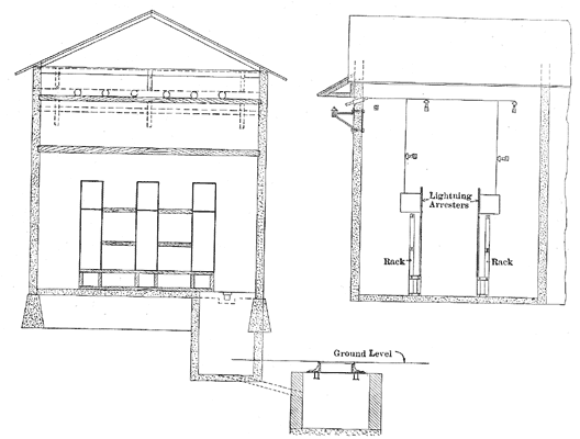
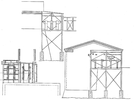
The terminal house on Mill Street is a one-story structure 21 by 34 ft. outside, and with concrete walls 8 in. thick. An internal wall of concrete divides the interior of this house into two equal parts, and two of the four three-phase circuits enter each half. A wooden cross arm is secured with its center 22 in. from the outside of the wall at each end of the building by iron brackets, and with its top 16 ft. 10 in. above the ground. Each of these cross arms carries six porcelain insulators mounted with their centers 3o in. apart, and to each of these insulators a bare conductor of one of the transmission circuits is attached. Somewhat above these insulators and with their outer ends slanting downward boxwood bushings, each 4 in. x 4 in. x 12 in., pass through the concrete wall, one bushing opposite each insulator.
Each of these bushings carries a glass tube, and through this tube the bare wire from the nearest insulator passes. Inside of the terminal house the bare conductors pass to other porcelain insulators mounted on cross arms, and each conductor is connected to a series of lightning arresters before it joins the cable. Above each cross arm on the outside walls of the terminal house a slanting weather shield is built. By means of the 8-in. concrete wall inside of the terminal house the pair of circuits that enter on one side is protected from damage by any short-circuit that may occur on the pair of circuits at the other side.
After leaving the terminal house the twelve bare conductors that make up the four three-phase circuits pass over a short pole line to the Victoria Bridge. This is one of the few instances if not the only one, where bare conductors carrying current at as much as 22,000 volts are brought on poles within the limits of a great city.
 |
| Fig. 3. Terminal House on Mill Street. |
 |
| Fig. 4. Terminal House at Chambly. |
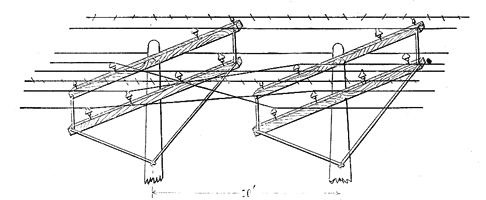
At the bridge the bare conductors are carried on heavy timber fixtures entirely over the top of the trusses. Each of the twelve conductors that make up the four transmission circuits is a solid, medium-drawn copper wire, No. 00 B. & S. gauge. These circuits are carried on two pole lines, there being two circuits per pole. Each three-phase circuit is arranged on two cross arms and on one side of its pole. On the lower of these two arms two wires of the same circuit are spaced 3o in. apart, and the third wire of this circuit is located on the upper cross arm at a distance of 28 in. from each of the other two. The transmission line between the terminal house on Mill Street and the power station at Chambly is 16 miles long. Over the Victoria Bridge one circuit of each pole line is transposed three times, and the other nine times to nullify the effect of the iron. Between the bridge and the power plant each of two circuits is twice transposed; hence this part of two circuits, one of either pole line, is divided into three sections of equal lengths. Each transposition is effected between two poles placed 10 ft. apart, each wire of a circuit being rotated through 120° between these poles. This transposition is carried out to overcome the effects of mutual induction, and as a protection to telephone and telegraph lines. The standard distance of the lowest wires in these circuits above the ground is 32.5 ft., and the regular length of span is go ft. Between the angle poles on the line the normal length of span is reduced to 5o or 75 ft., and such poles have double cross arms if the deflection of the conductors is more than 15°. The two pole lines, each carrying two three-phase circuits, are located 50 ft. apart on either side of the right of way.
No lightning arresters are connected to these transmission lines save at the terminal house and at the generating station. Along the entire line three grounded wires are strung on each set of poles as a protection against lightning. As may be noted from the above, the upper cross arm on each pole carries only two power wires, one belonging to each transmission circuit. Near each end of this cross arm and 32 in. from the power wire on that side, a barbed wire is mounted on a pony glass insulator. This barbed wire is made up of two No. 12 B. W. G. galvanized iron wires twisted with a four-point barb every 5 in. Another barbed wire is strung on pins in the pole tops. At each pole a ground wire is soldered to each of the barbed wires, and this wire is stapled down the side of the pole and twisted several times about its butt before the pole is set in the ground. Insulators are used to mount the barbed wire, because of the superior mechanical support thus obtained, but with no desire to insulate it in any way. No damage by lightning has ever been done to these transmission lines having the barbed wires, while shorter distribution circuits in the same locality have suffered severely from the frequent thunder storms that occur there. For this reason the grounded barbed wires are thought to afford a high degree of protection.
On the same poles that carry the transmission circuits two No. 12 hard-drawn copper wires are run for telephone purposes. These telephone wires are attached to the poles by side brackets and pony glass insulators, and spun or barrelled throughout. The telephone wires are 6.25 ft. distant from the nearest wires of the transmission circuits. Stations with jack boxes are located at intervals on the poles for the use of line inspectors, and telephones are connected to the two wires in multiple. For the protection of both users and telephones the latter are provided with film cutouts. Between the telephone wires and the ground there is an induced pressure of 125 volts. In case either of the telephone wires is broken or they are short-circuited, signals are transmitted according to a prearranged code by means of small incandescent lamps, using a telegraph key, the ground and one of the telephone wires to make a circuit.
All of the insulators that support the bare copper conductors of the four three-phase circuits are of white porcelain and were made by R. Thomas & Sons, East Liverpool, Ohio, under the trade designation of 6-in. Boch T. P. and Mershon type. Porcelain insulators were selected rather than glass because of their greater strength. Each of the 6-in. Boch insulators is 5 ½ mounted on its pin the lower edge of the outside petticoat is 4 1/2 in. above the top of the cross arm. A sleeve from the interior of each insulator follows its pin down for a distance of 2 1/2 in. below the edge of its outside petticoat. Each wire is carried on the top of its insulator and is then 8 1/2 in. above the cross arm.
 |
| Fig. 5. Pole With Cross Arms in Position. |
 |
| Fig. 6. Transposition Poles. |
Conductors nearest to the pole are distant about to in. from its side, and neither of the conductors is nearer than 18 in. to the iron braces of the cross arms. From conductors mounted on insulators of the lower cross arm to the lower side of upper cross arm the distance is about 9 in. These insulators were tested at the factory with a pressure of 80,000 volts while immersed in salt water.
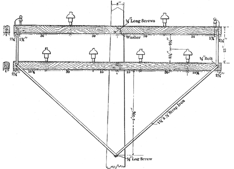
Pins for the insulators on which the transmission wires are mounted are made of hickory wood boiled in stearin and the part entering the cross arm has a diameter of 1 1/2 in. Each pin is secured in the arm by a 2 1/2-in. wire nail driven into both. Each cross arm for the three-phase circuits measures 11 ft. by 5 by 4 in., and is made of Georgia pine boiled in liquid asphalt. Gains for the cross arms were cut 1 in. deep in poles, and each cross arm was secured with three 1/2-in. lag screws. The two cross arms on each pole have their centers 23 in. apart and are braced by four pieces of strap iron each 1 1/2 by 1/2 in. in cross section. One piece of this iron is bolted to both the arms near each end, and the other two pieces pass from the ends of the lower cross arm to a point on the pole 4 ft. 5 1/2 in. beneath its lower side, and are secured at that point by a common screw bolt that passes into the pole.
Corner poles on the transmission line are guyed with steel cable, or braced with wooden struts, or both, and guys where used are attached 18 in. below the lower cross arm. Each of these guys is provided with a strain insulator. Most of the poles used on the transmission lines were round cedar, but a few were steel. Cedar poles of all lengths were required to be of not less than 8 in. diameter at the top, and 18 in. at the butt. The butts of these poles were tarred and the tops were rounded to shed water. Poles were set in earth as follows: Poles 35 to 45 ft. long, set in earth 5 ft.; 50 to 55 ft. long, set in earth 6 ft.; 60 to 80 ft. long, set in earth 7 ft. Where the ground is marshy the butts of poles are set in concrete for greater stiffness.
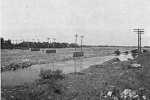
A short distance down stream from the power station at Chambly the two pole lines with their four three-phase circuits cross the Richelieu River. For this crossing six spans were employed, and six concrete piers were erected in the river to support the poles, two poles being set in each pier. Each pole at this crossing is provided with double cross arms, so that each of the twelve 2/0 copper wires has two points of attachment at each pole. The length of each of the spans across the river is about 125 ft. Not far from the river crossing just named the transmission circuits cross the Chambly Canal through which boats pass between Lake Champlain and the St. Lawrence River.
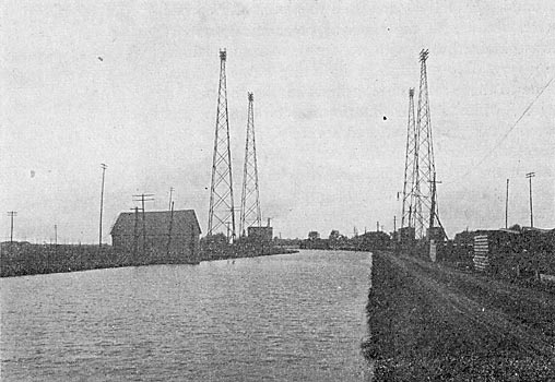
The length of span over this canal is about 132 ft., and with a sag of 5 ft. in the wires that make the span their height above the water in the canal is not less than 131 ft. For the purpose of carrying the circuits over this canal four steel towers were erected, two towers being used for the circuits on each of the two lines of poles. In view of the recent talk about the substitution of steel towers for wooden poles, to carry transmission lines, the details as to the size, weight and cost of the towers in this case may be of especial interest. Each pair of towers was designed to carry twelve No. 2/0 bare copper wires whose diameters had been increased to I in. by ice, and to resist all wind pressures without a strain in any member of more than one-fourth of its ultimate strength. The vertical height of each tower is 144 ft. above the foundation. At the top each tower measures 16 1/2 by 16 1/2 in., exclusive of cross pieces that receive the cross arms. Not less than 121,000 pounds of steel was used in the four towers, and their contract price erected on foundations furnished by the purchaser was $5,670, in January, 1902.
Each tower is provided with a ladder, and supports three sets of cross arms, each set consisting of four cross arms in one horizontal plain. One set of cross arms rests on the top of the tower, the center of the middle set is 30 in. below that of the highest, and the center of the lowest set is 3o in. below that of the second. Two cross arms of each horizontal set are on one side of the tower, and the other two arms of that set are on the other side. Each of the wooden cross arms on the towers is 13 ft. long, and the width across the four arms that make up a set is 4 ft. 1/2 in. Each set of cross arms provides four insulators for the support of each wire passing over them. Before entering the terminal house at the river end of the power station at Chambly, the four transmission circuits are attached to insulators carried by a heavy limber frame just outside. This frame carries four insulators for each conductor.
The terminal house itself is a one-story structure of steel and concrete, and is separated from the main power house by the end wall. In plan the terminal house is about 18 by 29 ft., and it rests on a steel framework that puts its first floor about 20 ft. above the foundation. The steel I beams on which the terminal house rests extend out about 12 ft. beyond its river side in order to support the timber framework to which the transmission lines are attached.
After leaving an insulator on a cross arm 22 in. from the outside of the concrete wall of the terminal house, each bare conductor passes through a glass tube surrounded by a wooden bushing in that wall. Each of these bushings is of oak 4 in. in diameter, 12 in. long and was boiled in stearin. A little distance inside of this wall each bare 2/0 wire is dead-ended on an insulator like those outside, and an insulated cable is here connected and runs thence to the step-up transformers in the power station. Near the juncture of the bare conductor and the insulated cable a wire is connected that runs to a series of 38 lightning arresters of the brass cylinder and air-gap type, each arrester having six gaps. Between the point where the series of 38 lightning arresters is connected to one of the transmission wires, and the point where this wire is connected to its transformer three inductance coils are inserted in series with each other. Each of these coils is flat, contains 14 turns and is one turn wide.
In each series of lightning arresters the twelve arresters nearest the earth are in shunt with a German silver resistance, and another resistance in series with all of the lightning arresters of each series completes its connection to earth through a copper plate 4 x 6 ft. by 1/8 in. in running water. Knife switches are provided in the 25,000-volt lines at the terminal house, and all of these lines are connected to static ground detectors. From the lightning arresters and knife switches the four three-phase circuits pass directly to the step-up transformers in the main part of the station. These transformers are connected Scott fashion in pairs, each pair receiving two-phase current at 2,200 volts, and delivering three-phase current at 25,000 volts. There are ten of these transformers, each rated at 2,750 kw, so that their combined capacity is 27,500 kw. These transformers are of the air-blast type and Westinghouse make. Both the transformers at Chambly water power plant and at the central sub-station in Montreal are Scott-connected. At the power plant the neutral connection of transformers is grounded on the high-tension side, and at the central sub-station there is a ground connection through a spark-gap to the neutral on the low-tension side. These ground connections are made for the purpose of protecting the transformers from lightning discharges. At the sub-station just named the transformers, which are of Westinghouse make, have each a grounded shield between their primary and secondary windings for protection to the secondary.
