[Trade Journal]
Publication: Elektrotechnische Zeitschrift
Berlin, Germany
p. 1029, col. 2
The electrical properties
of porcelain insulators at high voltage.
Porcelain insulators play the role of small capacitors in wiring systems. The wire forms one layer, the support (earth) the other and the porcelain mass the dielectric. The capacitances of these individual capacitors are located below themselves and in parallel with the larger capacitance of the wire to earth. If one looks at insulators from this point of view, a number of interesting questions inevitably arise which can only be answered on an experimental basis. For this reason, I attempted several years ago to obtain numerical evidence of the losses and other electrical quantities in porcelain insulators at high voltage, especially since I could not find any information on this in the literature I was following. My efforts at the time failed due to the imperfection of the tools available to me, since the quantities which I was trying to determine cannot be measured with any degree of certainty using normal laboratory equipment. However, after the Hermsdorf Porcelain Factory S.-A. had set up an excellently equipped test field especially for insulator testing ("ETZ" 1902, p. 471), it seemed to me time to resume the study of the question there under more favorable conditions. The tests, which I report on below, took place in September of last year, and it is a pleasant duty for me to thank the company for the permission they so willingly granted, as well as Mr. Dipl. Ing. Ritter, who took great care to carry out the tests himself. The dielectric of the line capacitance is air, which is assumed to have no electrostatic hysteresis. The situation is different with small porcelain capacitors. In these, losses will occur which are caused by two different processes. Firstly, electrification of the dielectric occurs and then there is a certain surface conduction. It is also perfectly acceptable to assume that a certain conductivity still exists through the mass, which can cause ohmic losses, but it can be safely assumed that this completely disappears compared to the surface conduction. If one looks at insulators from this point of view, a number of interesting questions inevitably arise which can only be answered on an experimental basis. For this reason, I tried several years ago to obtain reasonable evidence of the losses and other electrical quantities in porcelain insulators at high voltage, especially since no information on this could be found in the literature I was following. My efforts at that time failed due to the imperfection of the tools at my disposal, since the quantities to be determined cannot be measured with any degree of certainty using the usual laboratory equipment. However, after the Hermsdorf S.-A. porcelain factory had set up an excellently equipped test field specifically for insulator testing (ETZ 1902, p. 471), it seemed to me time to resume studying the question there under more favorable conditions. The experiments, which I report on below, took place in September last year, and it is a pleasant duty for me to thank the company for the permission they willingly granted me, as well as Mr. Dipl. Ing. Ritter, who took great care to carry out the experiments himself.
·
·
·
·
The support holes in which the chains K hung were filled with water. Taking into account the fact that in practical operation the lead wire is in the crown groove and the binding wire in the neck groove, the head of an insulator is covered with wire in such a way that the results of the chosen test arrangement should correspond to reality. T was a high-voltage transformer for 5.5 KW with a transformation ratio of 1:640 and 50,000 V normal. All the measuring instruments were in the low-voltage circuit and consisted of a precision wattmeter w from Siemens & Halske, a precision voltmeter E and an ammeter i of the same type from the Allgemeine Elektricitäts-Gesellschaft. The voltage curve of the machine was sinusoidal, the frequency in all tests was 50.
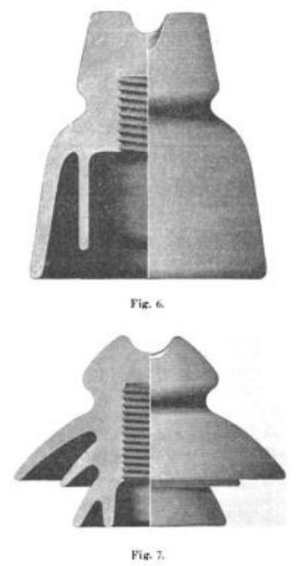 |
In order to find the values attributable to the insulators, the test setup was such that initially i and w were removed as f (E) and finally 90 insulators each, which were determined simultaneously when the chains were switched off. Test series with 10, 30, 50 and 70 insulators each were carried out when the transformer T was switched on, but these only served as internal controls and to detect possible sources of error. Only the series of observations on the largest number of insulators (90) were used to calculate the curves. The measurements should be carried out as quickly as possible and, if possible, in the same test arrangement for the bells to be compared, because, particularly at high voltages, when everything begins to glow and the radiation and ozone formation become significant, the entire test arrangement is sensitive to a variety of influences, all of which are not easy to overlook. The extent to which even small masses of metal lead to radiation losses and show a noticeable capacitance at high voltages is evident from the following experiment. If the high-voltage transformer was switched on by itself, i.e. with completely free secondary terminals, it consumed 315 watts and 5.4 A at 78 V primary (~ 50,000 V secondary), corresponding to a cos y = 0.75 (Fig. 5). If the experiment was repeated after the test device without bells (called the open-circuit test device above) had been connected to the high-voltage terminals, the current fell to 5.15 A and the watts rose to 363, corresponding to a cos q = 0.90. A current component of 1.5 A was added, which was mostly charging current (1.38 A), but also contained a small component (0.62 A) to cover the radiation losses (48 watts). The equivalent (fictitious) resistance for these losses is given as Two types of insulators were tested for approximately the same operating voltage. The edge discharge voltage served as the criterion for this.1) Type I, shown in Fig. 6, is an insulator of an older design; it weighed an average of 1550 g and had an edge discharge voltage of 21000 V. Type II, shown in Fig. 7, is the well-known delta bell from the Hermsdorf porcelain factory; it weighed an average of 900 g and had an edge discharge voltage of 22000 V. Both insulators were tested with a voltage of up to 50000 V. These are values that are not relevant for the practical use of these bells. They were used to determine the course of the curves as accurately as possible and also to find out the numbers to be expected for bells with higher voltage, at least in terms of the order of magnitude. Fig. 8 shows the results in graphic form for Type I and Fig. 9 for Type II, in accordance with the explanations in Section II. The coordinate scales are the same in both cases and the results are therefore directly comparable. Tables 1 and 2 are derived from Fig. 8 and 9 and give the individual values even more precisely in increments of 5000 V. The tests show first of all that the absolute values of the currents are small and only count in fractions of milliamperes, and furthermore that the rcine charging current component predominates and is about 5 to 7 times greater than the loss component of the current. The watt consumption per bell is also not so
1) Edge discharge voltage is the voltage at which the voltage just begins to arc between the wire and the support in pouring rain. significant that one need have some concerns even for voltages that are much higher than those that are usual in Europe today. The phase shift is large and the cos y is therefore small, which is a good thing here in contrast to other processes in alternating current circuits, because it improves the efficiency. This itself is, depending on the quality of the bell, of the order of 80 to 90%, which may be a little surprising to some. The capacitance is also not significant and will only increase the natural line capacitance by a few percent, but it should not be considered negligible a priori.
If one looks at the individual values a little more closely, initially using the results of the newer bell (Type II),
it becomes clear that in both ic and f (E) | are reproduced, the capacitance and straight lines result. This means that the dielectric constant is independent of the voltage. In contrast, in f(E) is no longer a straight line, but a curve convex to the abscissa. This means that the fictitious resistance decreases with the voltage. The reason is evidently the radiation process that becomes stronger with increasing voltage, which is not surprising in this form that is not very suitable for high voltage. As a result of this circumstance, the resulting current i as f (E) can no longer be a straight line, although the small proportion of in to i means that the deviation in the graphic representation is not noticeable. It also follows from this that as the voltage increases, cos increases and the efficiency decreases.
ic firstly shows that the capacitance and thus the dielectric constant are independent of the voltage. With regard to iw, the result says that the fictitious resistance is also not influenced by the voltage. As a result, the resulting current i as f (E) is also produced by a straight line and the watt curve becomes a parabola, i.e. the losses are proportional to the square of the voltage. A further consequence of these results is that the angle q, as well as cos φ, η, R and C are constant. What has just been said applies only to the delta bell. The type I (older form) shows a different behavior. It remains correct that for it too, since ic as f (E) is defined by a straight line | The watt curve is now no longer...
·
·
