[Trade Journal]
Publication: The Journal of Electricity, Power and Gas
San Francisco, CA, United States
vol. 13, no. 12, p. 384-386, col. 1-2
THE "BB" METAL INSULATOR PIN.
THOSE who are interested in the troubles experienced in connection with the use of high potentials on long distance power transmission lines, have doubtless followed more or less closely the various articles that have appeared in THE JOURNAL OF ELECTRICITY, POWER AND GAS, and other electrical papers, describing experiences with the well known wooden insulator pin, and it is the purpose of this article to call attention to some new styles of insulator pins, which have been developed for the express purpose of eliminating many of the .troubles incident to the use of wood.
In many cases, a good sound wooden pin meets all requirements so far as mechanical strength is concerned, and just so long as it remains in a normal condition, but there are drawbacks, one of which is the effect of the weather, sometimes partially overcome by boiling the pin in paraffine or otherwise treating it. This treatment, however, adds considerable to the expense, and even when practiced the pin is still found wanting, since iu case the insulator itself should break down, the leakage of the current chars the wood, sometimes setting it on fire, in which case the pin is completely destroyed. Then there is often an electro-chemical action evident, which destroys the wood fibre, in time allowing the insulator to drop off, or under conditions of lateral strain, the pin breaks. This electro chemical action is sometimes called "digestion".
There is little need of going further into the details of the troubles experienced with wooden pins, since all who are interested in the development of a new pin have experienced them on their own transmission lines. Suffice it to say that there is a demand for a pin which shall be practically indestructible, either by fire (on account of leakage of current) or by "digestion" (on account of electro-chemical action), or by the elements, and there is practically but one method of accomplishing this, namely, by the use of metal.
| |||
| Cut No. 1 |
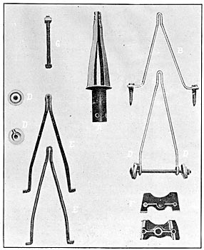
For the information of those who are looking forward to a cheap metal pin, there has been developed a cast iron pin as shown in Cut No. 1, and at A in Cut No. 4. This pin is designed with a hollow shank and with four small holes through the shank near the bottom, so that when it is placed in the hole in the cross-arm, a spike can be driven through the cross-arm, holding it in place. The diameter of the shank may be made to meet any condition that may arise. There is a very wide flange coining in contact with the top of the cross-arm, and from this flange there run upward four separate legs, coining together near the top forming a . . . [illegible text] . . . section; the top of the pin itself being notched in such a way that a lead cap can be moulded thereon, of suitable diameter and thread, to accomodate whatever type and character of insulator the consumer may desire to use.
Where conditions warrant, and the customer is prepared to pay more for his pins, this same casting can be properly malleabelized, but it is found that the malleabelization, when the high grade of iron used is considered, does not materially strengthen the pin. It, however, affords a pin which is not as susceptible to breakage under shock, as is the cast iron, and one which, under very extreme strains, will bend instead of breaking off, a feature which may often be of material advantage.
| |||
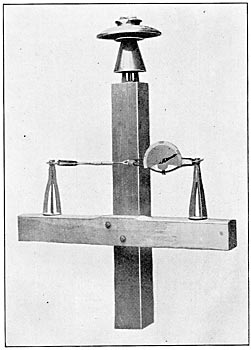
| Cut No. 2 |
| |||
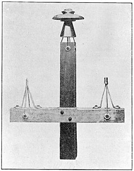
| Cut No. 3 |
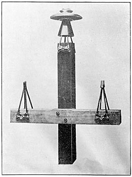
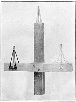
The wooden pin and the above described cast iron pin, are both open to the objection that they require a large vertical hole in the cross arm or the top of the pole, as the case may be, which hole materially weakens the structure, and it is often found necessary to add to the strength of the cross-arm or pole by inserting one or more bolts across the grain and at right angles to the hole for the shank of the pin, adding considerably to the expense. These same bolts can readily be used for the support of an insulator pin, properly designed and arranged to strap the cross-arm or pole top, thus materially adding to its strength. To meet this condition, two styles of steel wire pins, somewhat after the manner of a miniature Eiffel Tower, are supplied, as shown in Cuts Nos. 2 and 3.
| |||
| Cut No. 4 |
| |||
| Cut No. 5 |
The pin illustrated in Cut No. 2 comprises two elements shown in Cut No. 4 as B and C When it is desired to mount an insulator pin upon a cross-arm, one element B and one element C are used, crossing one over the other at the apex and moulding a lead top about them as shown in Cut No. 2. Element B may then be fastened to the cross-arm by means of lag screws or bolts as desired. The heavy washers illustrated at D having been especially designed to give ample contact surface with the cross arm.
Element C would preferably be fastened to the cross-arm by a bolt, though in this case lag screws could be used if found sufficient. It will be noted that elements Band C are provided with eyelets in the end, which are embraced and protected from spreading by the washer D, through which washer and eyelet the bolt or lag screw passes into the cross-arm. When this style of pin is desired for the top of a pole, two elements C, crossed one over the other, should be used, and a lead cap moulded thereon, the two bolts passing through the pole top at right angles to each other. When the two elements C are crossed, one above the other, the bolt holes will be brought one above the other, just sufficient so that they will clear. This pin is made of wire, as is also the one illustrated in Cut No. 3, and it has been demonstrated that they give ample strength; that they will not break under shock, and that the worst that can happen is when, under extreme lateral strain, they may be bent out of shape. It is, however, practically impossible, with the use of either one of these steel wire plus, to break or pull the pin away from its fastening to the cross-arm, and hence so long as the insulator itself remains intact, and the tying of the line wire to the insulator holds, there is practically no condition under which a line could be pulled away from its support.
Hardly any explanation is needed of the steel wire pin shown in Cut No. 3. It consists of two elements identical in every way, as shown at EE two heavy cast iron side plates as shown at FF and the one bolt as shown at G. The cast iron plates FF are provided with lips on the inner surface, so that when the bolt is drawn up, these lips are forced into the wood giving a rigidity to the pin which cannot be improved upon. Like the steel wire pin in Cut No. 2, the elements have to be partially assembled, and a lead cap moulded around the top of suitable dimensions and thread for the insulator which is to be used. To prevent one element sliding over the other under side strains, there is a small hole left in the bend at the apex of the pin through which a rivet is passed before the lead cap is moulded thereon.
It is obvious at once that these pins need not be treated in any manner for use in some localities, whereas in other localities japanning or coating with any good grade of weather proof paint would afford ample protection from the elements. At other points, and particularly near our coast line, it may be found necessary to have these pins galvanized.
The pins illustrated in Cuts No. 2 and No. 3 are, of course, applicable to any cross-arm or pole top now in use, andean be installed to replace wooden pins almost as quickly as a new wooden pin could be put in place. The fact that a vertical hole exists in the cross-arm or pole top does not militate against the use of these pins, since when they are installed they add materially to the strength of the cross-arm or pole, as the case may be.
These pins are manufactured in the East in large quantities at reasonable prices and shipped to the customer, who in his turn will assemble them at his shops as required, using a suitable mould for the threaded head and then distributing the pins upon the line just as they now do the wooden pins.
Owing to the extreme durability of these pins, the poles (in new construction) can be placed even more than double the usual distances apart, making a few long spans, and thus effect a very material saving in cost of line installation; spans of from 200 feet to 500 feet are thoroughly practicable.
The Wagner-Bullock Electric Company of California have the agency for the new pins, above described, to whom all inquiries should be addressed.
