[Trade Journal]
Publication: American Institute Of Electrical Engineers
New York, NY, United States
vol. 2, p. 152-176
THE CONSTRUCTION AND INSULATION OF
HIGH-TENSION TRANSMISSION LINES.
BY M. H. GERRY, Jr.
There are in America at the present time, about ten systems operating regularly at tensions of not less than 40,000 volts, and transmitting energy from sixty to one hundred and fifty miles. Two of these transmissions employ pressures of between 50,000 and 60,000 volts. The above mentioned systems have all been constructed within the past decade, and while they represent commercial enterprises of considerable magnitude their chief interest lies in the possibilities which they suggest for future developments. The following paper briefly discusses the problems connected with the construction and insulation of transmission lines, without touching upon the generation of the high-tension current, or its manipulation within the generating or receiving stations. The methods of construction and details of design described are drawn entirely from American practice. The term " high tension " where used refers to electrical pressures such as mentioned above.
GENERAL DESIGN.
In the construction of high tension transmission lines wooden poles have been used for supporting the conductors almost exclusively, but there is a tendency at the present time to substitute metal, and the more permanent material will doubtless be employed in the future wherever the undertakings are of sufficient magnitude to justify the larger investment. Excellent results have been obtained, however, from the lines now in operation, and the current practice may be followed with a certainty of satisfactory performance and reasonable cost of construction.
Many of the transmission systems are located in a mountainous country difficult of access, and the obstacles overcome have been numerous and varied. Whenever the nature of the service is important a private right-of-way has usually been secured and two lines of poles erected.
Cedar poles are used in the .majority of cases, but redwood, pine and other woods are also employed to some extent. Cedar has an advantage over the other common woods in that it will last longer in moist ground. The pole tops and butts are frequently treated with coal-tar, or some preservative compound, but this practice is not universal. Poles for important transmission lines are usually selected with care, and are heavier and of better timber than those for other classes of service. They are of lengths varying from thirty-five to seventy-five feet, with diameters at the tops of from eight to fourteen inches.
For conductors both copper and aluminum are employed. Copper is used as a solid wire in the smaller sizes, and as a stranded cable when of considerable dimensions. Aluminum is now always employed as a stranded cable. With either metal the flexibility, elasticity and strength are improved when in the form of a cable. Copper may be obtained either soft or hard-drawn. The hard-drawn material has greater tensile strength than the soft or annealed, and for that reason is often preferred. Copper conductors should not, however, be subjected to a greater strain in service than the limit of safety of the soft metal, for the reason that the hard-drawn material may be annealed locally, either during erection while making connections, or while in service by the heating of a joint, or from a short circuit. Aluminum is much the lighter metal for equal conductivity, and this is of some advantage during construction. On account of the greater coefficient of expansion of aluminum, more attention is necessary to temperature conditions at the time of erection, so as to limit the sag and resulting stress developed. Equally good results may be obtained, however, with either metal if properly installed.
The cross-arms in use on most transmission lines are either of fir, or of long-leaf yellow pine. Selected timber is usually employed, and the cross-arms are of special dimensions for this service. In the future structural steel will probably be used to a considerable extent for this purpose.
The pins supporting the insulators are made either of wood or of metal. Of the various kinds of wood, locust, oak and eucalyptus are most in use. Mountain locust from old trees is perhaps the most satisfactory, but is difficult to obtain. Oak if well seasoned gives good results, and eucalyptus has some excellent qualities. Metal pins are made of steel or cast iron. Steel pins are the more reliable, as they are not subject to flaws, and do not fail from internal strains. For fastening together the poles, cross-arms, braces and pins, through bolts are now usually employed.
 |
| Fig. 1.- Pole Top for High-Tension Transmission Line, Washington Water Power Company. |
Various details of construction from current practice are shown in the examples to follow.
 |
| Fig. 2.- Steel Pin, Washington Water Power Company. |
The standard pole construction of the Washington Water Power Company is shown in Fig. 1. This company has recently completed an important transmission, one hundred miles in length, designed for an ultimate tension of 60,000 volts, although now operating at 40,000 volts. The conductors are of No. 2, B. & S. gauge, medium hard-drawn, solid copper wire. The insulators are of porcelain and are brown glazed. The distinctive features of this construction are the short distance of forty-two inches between conductors, and the special form of steel pin employed to support the insulators. This pin is illustrated in Fig. 2 and is worthy of notice. It was designed by Mr. D. L. Huntington, general manager of the company.
 |
| Fig. 3.- Pole Top for High-Tension Transmission Plant, Shawinigan Water & Power Company. |
 |
| Fig. 4.- Pole Top for Transmission Line, Madison River Transmission. |
Another interesting illustration from current practice is shown in Fig. 3, which is the pole top made use of by the Shawinigan Water and Power Company for their Montreal transmission. The length of this line is about eighty-four miles, and it is now operating at 53,000 volts. The conductors are aluminum cable, each made up of seven strands of No. 7 wire. The insulators are of porcelain, made in three parts, and are supported on wooden pins. They were especially designed for this installation by Mr. Ralph D. Mershon, the consulting engineer of the company.
 |
| Fig. 5.- Special Four-Post Line Tower, Guanajuato Power & Electric Company. |
 |
| Fig. 6.- Pole Top for High-Tension Transmission Line, Guanajuato Power & Electric Company. |
A novel construction is shown in Fig. 4. This is the arrangement used by the Madison River Transmission operating into Butte, Montana. It is remarkable for the entire absence of metal, with the exception of the conductors. The cross-arm extends through the pole, and is held in place by wooden wedges and a wooden pin. This line is about seventy miles in length and operates at 40,000 volts. It employs glass insulators supported by wooden pins, and the conductors are of aluminum cable. It was built under the direction of Mr. P. N. Nunn.
A transmission which employs steel towers for supporting the conductors, has just been completed in Mexico by the Guanajuato Power and Electric Company. Fig. 5 shows a standard tower, and Fig. 6 the arrangement of cross-arms, pins and insulators. The towers are of a type used for supporting windmills, and are of very light construction, the various parts being fastened together by means of special bolted fittings. All the metal parts are galvanized. The towers are supported by anchors held in place by concrete foundations located at the four corners of the structure. A length of extra heavy 3-inch pipe, supporting the cross-arm and the top pin, extends above the tower. The pins are of cast iron, and the insulators of porcelain. The spans are said to average five hundred feet, while the sag of the conductors is about eighteen feet. The conductors are of hard-drawn copper cable. This transmission is intended ultimately to operate at 60,000 volts.
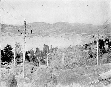
As a further illustration of current practice, the high tension lines of the Missouri River Power Company, built under the direction of the writer, are here briefly described.
This transmission has been in service for over three years, operating at 57,000 volts, delivering power at a distance of over sixty-five miles in a satisfactory manner. The country through which it passes is very rough as shown in Fig. 27.
|
| |||
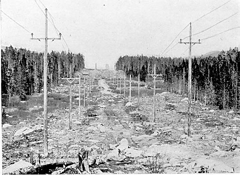
| Fig. 27. and Fig. 28.- Missouri River Power Company's Transmission Lines. |
The lines leave the generating station at an elevation of about 3,700 feet, pass over three distinct summits, including the Continental Divide, at which point they reach an elevation of 7,300 feet above sea level. There are two parallel lines extending from the generating station on the Missouri River to the Butte substation. They are located in the main on a private right of way 200 feet in width, from which all timber was removed. Each of the lines carries three copper cables arranged in a triangular position, seventy-eight inches apart. The cables are composed of seven strands and have an area of 106,000 circular mils. Fig. 7 illustrates the upper part of a standard pole. Fig. 8 is a section of the insulator, sleeve, pin and pole-top.
 |
| Fig. 7.- Pole Top, High-Tension Transmission Line, Missouri River Power Company. |
 |
| Fig. 8.- High-Tension Insulator, Sleeve, Pin and Pole Top, Missouri River Power Company. |
The poles are of Idaho cedar, the cross-arms of Oregon fir, the braces and pins of white oak, and the insulators and sleeves of glass. The cross-arms, braces and pins are held in place by means of through bolts. The pins in the top of the poles are of larger size and of greater length than those in the cross-arms, to provide for the greater strains there present. The pins were prepared by being first dried and then treated in paraffine, until all moisture was removed, and were then tested to 60,000 volts. The glass sleeves are not fastened to the insulators and merely rest on a shoulder of the pins, as shown in Fig. 8.
The circuits are transposed five times, making two complete turns between the generating station and the substation. The switching arrangements are such that the circuits may be operated either singly or in multiple. A telephone circuit is located on one of the lines and gives good results in service. The poles are from thirty-five to seventy-five feet in length, and the pole-tops are from nine to twelve inches in diameter. The poles are set from six to eight feet in the ground, according to height, and the standard spacing is one hundred and ten feet, with a maximum spacing of one hundred and fifty feet, when required by the nature of the ground. Fig. 28 shows the lines through timbered country.
The constructions just described were selected as typical examples of what has been accomplished in the building of high tension transmissions. Several of the lines mentioned have been in regular operation for periods varying from one to three years, and are in no sense experiments, but rather represent successful commercial undertakings. Other interesting and well-known systems might have been described had the limits of this paper permitted a further expansion of the subject.
LINE INSULATION.
The design of insulation for high pressure should involve a consideration of all the effects of electrical tension on the dielectric in the vicinity of the conductors. In the case of a line insulator, air is always a dielectric in combination with glass, porcelain, wood or other materials. Wherever there is a difference of electrical potential there exists in the surrounding media a certain state of strain called an electro-static field. This state of strain is the result of electrical stress applied to the insulating material. Dielectrics possess a sort of atomic elasticity, and electrical tensions produce a displacement in the molecular structure which, if carried beyond a certain limit, result in disruptive breakdown of the material. Before a difference of potential can exist current must flow into the dielectric, thus producing a state of strain equal to the electrical stress applied. If the material be not strained beyond its limits of molecular elasticity, current will flow from the material whenever the tension is removed or reduced, and a path provided. All dielectrics possess the quality of receiving strain before rupture, but not to the same degree. Solids and liquids generally possess it in a higher degree than gases. -Whenever the limit of strain of a particular material is exceeded it fails structurally, resulting with a solid in a mechanical rupture, and with a gas in a change of molecular state which reduces its electrical resistance and renders it semi-conducting. It frequently happens when several dielectric materials are subjected to the same electro-static field, that one or more of the materials will be strained beyond the limit and will fail, although the others may withstand the electrical tension. Air adjacent to powerful dielectrics frequently fails in this manner, thus giving rise to the common brush discharge.
The structural failure of air, from an engineering standpoint, has been studied by a number of investigators, including Mr. C. P. Steinmetz and Prof. Harris J. Ryan. It is well known that air at ordinary pressures and temperatures has a much lower dielectric strength than the common solid insulating materials. Air in thin films adjacent to solid bodies has greater strength than in bulk, but is still inferior to such substances as glass, porcelain, mica, treated paper, etc. The dielectric strength of air is affected by its physical condition, and varies directly as the pressure and inversely as the absolute temperature. Under uniform conditions all dielectrics rupture at definite applied tensions. Prof. Ryan has shown that there exists also for each dielectric material a certain strength of electro-static field which will cause rupture. When several materials in series form the dielectric, the one rupturing at the lowest value of electro-static field will fail first although individually it may possess superior qualities.
 |
| Fig. 9.- Tension Applied to Disc. |
Line insulators are usually made of glass or porcelain, fashioned into a variety of shapes, all approximating certain elementary forms. Consider that alternating electrical tension be applied to a solid insulating disc, as shown in Fig. 9. If the pressure be low, only charging current will flow, but if the tension be increased sufficiently the air under and about the electrodes will be ruptured, producing brush discharge. This results in the formation around the electrodes of a zone of ionized air, of comparatively low resistance. This enveloping zone of conducting air has the effect of increasing the size of the electrodes, and thus the area to which the full tension is applied. If the tension be further increased, the zone of ionized air continues to spread over the surface of the disc, thereby increasing its capacity and the resulting charging current. Streamers will now form on the surface of the plate, and thus afford a path of still lower resistance whereby the current for charging the dielectric and ionizing the air is conducted to the outer portions of the ruptured zone. When the surfaces of the solid dielectric are parallel, as in this case, the streamers and ruptured air zone when once started, would apparently continue to spread indefinitely, were it not for the cooling effect of the adjacent material, the appreciable resistance of the path through the ionized air, and the time element introduced by the alternating pressure.
 |
| Fig. 10.- Tension Applied to Disc by Means of Enlarged Electrode. |
Tinder the conditions as shown in Fig. 9, the streamers may unite over the edge of the plate, thus forming a short circuit, the distance traveled being several times as great as the breakdown distance through air for the same pressure. This result is not due to surface leakage, as frequently assumed, but is a phenomena of electrostatic capacity and local structural failure of the air as a dielectric. If instead of the pressure being applied to a small area, as in Fig. 9, the electrode be enlarged to a plate, as shown in Fig. 10, the same results will follow, but the spreading out of the ruptured air zone will take place on one side only and at a considerably lower tension. If pressure be applied to an insulating tube, by means of a conductor inside and outside, as shown in Fig. 11, the air will fail at a certain tension, and the results will be similar to those obtained with the plate, in Fig. 10. The streamers will start from the conductor on the outside at A, and will run along the tube from the center toward the ends, the tendency being to cover the outer surface with an enveloping coating of ruptured air.
 |
| Fig. 11.- Tension Applied to Insulating Tube. |
In this, as in all other cases, the streamers are drawn out in such a direction as to increase the electro-static capacity. If a still greater tension be applied, the streamers from A will finally draw sufficiently near to B to cause rupture of the air in bulk between B and the ends of the streamers extending from A. If, under these conditions, the internal conductor be now removed from the tube, as shown in Fig. 12, the air about the point A will no longer be ruptured, and the streamers will cease, although the distance between A and B, and also the conditions for surface leakage remain as in Fig. 11. It will now require a material increase of tension to cause a breakdown between the electrodes, and this will occur essentially as if the tube were not present.
 |
| Fig. 12.- Tension Applied to Insulating Tube, Internal Conductor Withdrawn. |
 |
| Fig. 13.- Tension Applied to Insulating Dish. |
 |
| Fig. 14.- Tension Applied to Insulating Receptacle. |
 |
| Fig. 15.- Tension Applied to Special Form of Insulator. |
After initial rupture of the air, the spreading of the streamers is affected to a degree, by the form of the solid dielectric. Fig. 13 indicates tension as applied to a dish of uniform thickness, Fig. 14 to a deep receptacle, and Fig. 15 to a special form. The results obtained from the arrangement shown in Fig. 13 will not differ materially from those obtained from the arrangement shown in Fig. 9, or if one surface be made conducting, from those obtained from Fig. 10. In the ease of Fig. 14, however, the air in the interior of the receptacle about the entering conductor becomes ionized at sufficient tension, and the conditions then existing are the same as if the receptacle were filled with a conducting substance. With the arrangement in Fig. 15 the streamers start as in Fig. 9, but upon reaching the downward projection they are forced along its surface and away from the streamers on the upper face of the plate, until a point is reached where the electro-static field is no longer sufficient to rupture the air, when the streamers die out and further spreading of the ruptured air zone ceases.
All line insulators are made from variations of the forms just discussed. Surface insulation has little to do with their performance, and excepting the faces be made conducting by a coating of water or other foreign material, the surface leakage may be neglected altogether from an engineering standpoint. A wet surface, however, is practically equivalent to the metallic coating illustrated in Fig. 10. For high tensions wet surfaces should be considered as conductors, but dry surfaces need be treated only in relation to the electro-static phenomena already described.
A first consideration in connection with the design of a line insulator is its ability to maintain dry surfaces under all weather conditions. It has been frequently assumed that rain descends at an angle not exceeding 45° from the vertical, but this is not a safe basis for design. When rain is accompanied by wind at high velocity, and especially if the air currents be unsteady and in "gusts", and subject to deflection on account of the irregular contour of the country, it will then be found that at times the rain travels practically in a horizontal plane. As the rain-drops are often moving at high velocity, there will be also considerable splashing of the water where it meets obstructions, and this must be considered in predetermining the dry surfaces. With insulators of the "umbrella" type, there frequently results a wetting of a portion of the under side of the main petticoat, from water splashed from other parts. The shape of the insulator may also result in deflecting the air currents, thus carrying the rain to surfaces that otherwise would remain dry. Insulators of the "Italian" and "Double-Story types are frequently affected in this way. Those of the vertical petticoat type are especially free from this defect, as the spaces between the petticoats are efficient in preventing eddying air currents from carrying moisture to the under side of the insulators.
After determining the extent of the possible wet surfaces, consideration should be given to the distribution of potential on the various parts of the insulator. The tension is applied between the point where the conductor is attached and some other point, depending upon the construction employed. During rains the entire upper surface. of the insulator is at the potential of the conductor, and the ground potential is at the least directly under the insulator at the cross-arm. This condition holds with wooden construction as well as with metal. If a conducting pin be employed, the ground pressure will be carried still higher, and the tension will be applied across the comparatively thin material of the upper part of the insulator. The dielectric will then consist of the porcelain or glass at this point, and the air adjacent to the conductor and pin. The tension will be that to ground, and for a three-phase circuit under normal conditions, will be less than the pressure between conductors, but as there are many operating conditions where full tension may be applied to the insulators, it is better practice, for the purpose of design, to assume that this is the case at all times. The form of the pressure curve also has an effect, as it is the maximum tension at the peak of the curve that causes initial failure of the dielectric.
If the tension as applied sets up through the material an electrostatic field sufficiently powerful, the air in series with the solid insulating material will be ruptured, and brush discharge and streamers will form, which unless checked, may extend over the entire insulating surface, causing short circuit. The spreading of the conducting zone of air may be prevented as previously explained, by the use of very large surfaces, or by employing deflecting projections, or petticoats, so arranged as to reduce locally the strength of the electro-static field to a point at which the air will not be ionized. These methods, however, serve only to stop the spreading of the ruptured air zone, and require considerable dimensions for even low factors of safety. All brush discharges are wasteful of energy, and are destructive of organic materials. It is brush discharge combined with capacity charging current that has caused the burning of pins on high tension lines. Common wooden pins are practically conductors for high tensions, and the ground pressure is carried up within the insulator. When the pins possess dielectric qualities comparable with the material of the insulators, the tension may be said to be applied between the top and base of the insulator, resulting in a greatly increased thickness of the dielectric material. This usually overcomes brush discharge and materially increases the reliability of the insulator. For the best results insulators for high tensions should be so designed that under no operating conditions would the electro-static field of force ever be sufficient to rupture the air adjacent to the insulating surfaces. This can be accomplished by properly proportioning the thickness of the material exposed to the electric stress.
The general dimensions of the insulator should, of course, be such that the direct air path from the conductor to the cross-arm will be sufficient to avoid failure through the rupture of the air in bulk. This is a matter of simple determination, involving only the length of the air path and the dielectric strength of the air in bulk at the extremes of pressure and temperature, as found in service. When insulators are made of several parts cemented together, the dielectric material is no longer homogeneous, and the distribution of the electro-static strain may be materially altered. The cements commonly used, such as sulphur, litharge and glycerine, Portland cement, etc., possess entirely different and inferior electro-static qualities to the glass or porcelain of which the insulators are made. The cement between the sections is in series with the dielectric material of the insulator, and is exposed to the same electro-static field of force. The strata of cement in some cases redistributes the electro-static charge. Under other conditions, the pressure is conducted directly to the cement through the ruptured air. In this case the semi-conducting cement becomes charged with practically the full terminal pressure, and excessive tension may thus be applied to a section of the insulator not designed to withstand it. This frequently results in sectional breakdowns, and the insulator fails in detail. The irregular distribution of surface potential also affects the outside air path, and in some types orinsulators reduces the tension required to rupture the air between the points of applied tension. When insulators are made up of several parts, the cement employed should possess dielectric qualities comparable with that of the component parts, and every effort should be made to render the dielectric material homogeneous so that there may be a uniform fall of potential between the points at which the tension is applied.
The resistance to disruptive breakdown or puncture of the solid dielectric is also of importance. Good porcelain or glass has, however, such great strength in resisting puncture that if the insulator be designed so as to entirely avoid rupture of the air near the points of applied tension, it will be impossible to puncture the insulator under operating conditions. One-piece insulators of glass or porcelain seldom fail from puncture, even if thin at the top, but two or three-part insulators sometimes fail by puncturing one or more of the sections, probably due to unequal distribution of potential, as previously discussed.
Of the various substances available, glass and porcelain have been used almost exclusively for high-tension insulators. Glass has excellent dielectric qualities, and can readily be obtained in desirable shapes, at reasonable cost. Its greatest defect is its mechanical weakness, which is due almost entirely to internal strains developed during manufacture. Consistent design of the surfaces so as to obviate as far as possible shrinkage strains, and careful annealing have improved the conditions of many glass insulators so as to render them reliable for service, but they still do not possess the mechanical strength of the best porcelain. Glass, however, is a more reliable dielectric material, and from an electrical standpoint gives better and more uniform results. The best porcelain has great mechanical strength and good dielectric qualities. It is, however, difficult of manufacture in considerable thickness, and is very apt to develop flaws and surface cracks. Common grades of porcelain are unreliable and should not be used for high tension work.
While the insulator has been considered chiefly as an electrical device, it is still essential that it be treated as a mechanical support for the conductors, which function it chiefly serves. Practically all the mechanical strains on the insulators and pins are transmitted from the conductor. When the line is level and without angles, and when the spans are equal, the strains are due only to the wind and weight of the conductor. When angles in the line occur, a transverse strain is developed. If the line be not level or the spans not equal, strains having vertical and horizontal components are produced. All the necessary calculations for the forces acting and the resulting strains can be readily made by the ordinary rules of mechanics, and do not here require consideration.
 |
| Fig. 16.- Section of High-Tension Insulator. |
The following described high-tension insulators were selected as representing American practice:
Fig. 16 shows a brown glazed porcelain insulator, of the "umbrella" type. It is made in three parts cemented together, and weighs about 20 lbs. This insulator is in use by the Washington Water Power Company already referred to in this paper.
Fig. 17 is a section of a glass insulator also of the "umbrella" type. It is made of two parts cemented together, and weighs 13 lbs.
 |
| Fig. 17.- Section of High-Tension Insulator. |
Fig. 18 shows the insulator in use by the Shaminigan Water and Power Company, now operating at 53,000 volts. It is of white glazed porcelain, in three parts. Its dimensions are given in the section. This insulator also weighs 13 lbs.
 |
| Fig. 18.- Section of High-Tension Insulator. |
Fig. 19 is a single-piece insulator of the "Italian type. It is made of fine porcelain, brown glazed, and weighs 7-3/4 lbs.
 |
| Fig. 19.- Section of High-Tension Insulator. |
Fig. 20 shows a porcelain insulator of late design. It is brown glazed and made in three parts. Its weight is 26 lbs.
 |
| Fig. 20.- Section of High-Tension Insulator. |
The insulator shown in section in Fig. 8 is the standard insulator of the Missouri River Power Company and is in regular service at 57,000 volts. It is of glass made in two parts, and its weight is 121 lbs.
Figs. 21 to 26 inclusive are reproductions from photographs of the insulators shown by the section drawings above referred to.
The developments in the construction and insulation of high tension lines have now reached a point where no doubt exists regarding the practicability of transmitting energy at tensions approximating 60,000 volts. From this time on it will be rather a question of expediency and engineering detail to determine the best methods of obtaining the desired commercial results. For pressures above 60,000 volts the field as yet is unexplored, but those who have followed this subject carefully agree that much higher tensions will ultimately be employed. The practices discussed in this paper, both for the general construction and for the insulation of high tensions, cover what has already been accomplished, but seem also to point the direction of future development in this branch of engineering.
 |
| Fig. 21 to 26.- High Tension Insulators. |
Discussion.
Mr. GERRY : In opening the discussion on Mr. Converse's paper, I wish to call attention to one or two points in connection with insulator design which I believe have been overlooked. This has resulted, among other things, in the discussion of the relative merits of iron and wooden pins. There is little ground for discussion on this point; both iron and wooden pins have their respective values in particular cases. When properly applied, either will answer the purpose. Furthermore, because of these certhin points having been overlooked, the great differences have arisen in high-tension insulator designs. I have recently examined an insulator weighing 50 pounds, having petticoats 36 inches in diameter, but it did not possess proportionate strength for withstanding the ordinary conditions of line operation. Mr. Converse has stated that surface leakage has an important bearing on insulator design. My experience has been that leakage, as it is ordinarily understood, plays little or no part from an engineering standpoint. Unless the surfaces be covered with water, salt, or some conductive powder, there is no appreciable leakage of current. However, a somewhat similar effect on the surfaces may be produced by a film of ruptured or semi-conducting air, resulting from the application of too great electro-static strain. The electrical tension is applied to the opposite sides of the solid dielectric, but in an insulator the dielectric includes, in addition to the glass or porcelain, the air immediately surrounding the electrodes. Under these conditions, when pressure up to a certain point is applied, very little current flows into the dielectric only the small amount required to charge the material immediately adjacent to the conductors. If the tension be now increased, a point is finally reached at which the air near the electrodes is ruptured. This results in what is commonly known as brush discharge. The air becomes semi-conductive, and the electrode in effect expands, causing the charging current also to increase. This seeming expansion of the electrode, when once started, would go on indefinitely were it not for certain conditions tending slightly to retard it; such as the cooling effect, shape, and nature of the surface of the solid dielectric, and the time limit introduced by the current wave.
What actually happens, after the air is ruptured, is that the brush discharge finally extends over a certain limited area on both sides of the insulator. A comparatively slight increase in the potential applied w ill now greatly increase this area. In nearly all insulators recently designed, the solid dielectric is thin at the top where the tension is ordinarily applied. It follows that the air at this point is easily ruptured, and the brush discharge spreads from the electrodes over the surface of the insulator. Once started, it requires only a moderate increase in the tension to cause this brush discharge and its accompanying zone of ruptured air, to extend such a distance that an arc starts and a breakdown of the insulator results. Metal pins or wires inside the insulator, cause the tension to be applied directly across the thinnest part of the insulator, while insulating pins if of proper quality, form a part of the main dielectric, resulting in the tension being applied at more widely separated points. With mist insulators in common use, conducting or semi-conducting pins have been employed, and this accounts for the very narrow margin of safety mentioned by Mr. Converse in his paper. This factor of safety may be increased, however, by consistent designing of the insulator, or by the use of an insulating pin. It is thus possible to increase many times the thickness of the solid dielectric to which tension is applied, thereby enormously increasing the factor of safety under given conditions. If an insulator such as shown by Mr. Converse in Fig. 8 be supported on an insulating pin, it will be impossible to break it down, except through the main air path, and brush discharge will not start until the air in bulk is about to fail between the points at which the tension is applied the tie wire and the cross-arm. This result is due to the fact that the solid dielectric is then of sufficient thickness to prevent the formation of a sufficiently strong electrostatic field to rupture the air prior to the point of rupture being reached through the direct air path. This is one of the points to which I wish to call attention, and it is of the greatest importance in connection with insulator design. If high potentials are to be applied to very strong and comparatively thin dielectrics, the air is bound to rupture, and it will be necessary to resort to extreme sizes of petticoats to prevent the spreading of the brush discharge thus formed. If, on the other hand, a more logical design be followed, and the insulator so proportioned, that brush discharge will not result, then the insulator may be strained practically to the point of failure of the air between the points where the tension is applied.
Chairman SCOTT: If we consider both high-tension commercial service and time, I believe we must accord to Mr. Gerry the honor of having operated at the highest voltage over the longest time. Ile has been operating nominally at 50,000 volts but actually at 55,000 volts, in continuous commercial service for two years and a half. His line is about sixty-five miles from the power house of the Missouri Power Company, near Helena, to Butte, Montana. Other plants have operated at a little higher voltage, others have operated at longer distances, but taking all together high voltage, length of time, continuity of service, amount of power his plant may be taken as one of the foremost if not the foremost example of high-tension transmission at this time. I believe he told me that he had not lost an insulator through break-down on the line due to electrical causes.
Mr. CONVERSE: Mr. Gerry prefaced his remarks by the statement that his ideas of the essential features in the design of an insulator were somewhat at variance with those expressed in my paper. On the contrary, I think we closely agree as to one of the most serious defects in the design of high-tension insulators, which is the lack of a sufficient thickness of material around the head. Mr. Gerry mentions the brush discharges which occur around an insulator, and I believe made certain experiments with dielectrics of different shapes in order to show the character of the brush discharges. He then applies the experiments in the design of an insulator and, I infer, finds the proportions of the insulator. Mr. Gerry's analysis discloses nothing new, and its results are rather doubtful. It would seem to be desirable to devise some way of measuring the potential differences between the various parts, in order to determine the rational design. I am inclined to agree with Mr. Gerry that wooden pins have been burned by the brush discharges and not by surface leakage of current. As to whether an iron pin will become a detriment in a very high-voltage insulator, I am in doubt; but incline to the belief that it may be found to be the means of securing the proper distribution of potential.
Dr. F. A. C. PERRINE : In these two papers, two essential elements in insulator design are stated, namely, that the potential gradient from wire to ground, whether the ground be pin or whatever it be, shall be as gradual as possible, and that all surfaces exposed shall allow as complete a distribution of potential as is possible. These two principles, I think, are the absolutely essential elements of insulator design, and it is fortunate that in the midst of a lot of floundering, the men who have been actually building high-potential insulators have at last arrived at a correct scientific theory of the design of an insulator. Mr. Gerry has, fortunately for me, expressed very clearly the first principle. If we have two surfaces charged, then the tendency to break down the air is proportioned to what we may call the potential gradient from one surface to the other. As we narrow their distance, the potential gradient becomes steeper and there is more tendency to discharge around their edges. The other point is simply the question of discharge between surfaces. We all know that if we have two points presented to each other,- there is a greater tendency to discharge than if we have two planes. We have at the petticoat edge of every insulator what is essentially a line of discharge. Now, to reduce the tendency to discharge from a line to any surface, we have to present to that line a semi-cylindrical surface. If we have in equivalent position a plane surface, there is more tendency to discharge to the nearest line in the plane than if an equipotential semi-cylindrical surface was presented at a distance equal to the minimum distance of the plane. In consequence, in all insulator designs, we will have the least tendency to discharge from the circular line formed by the bottom of a petticoat which is a conducting line, as Mr. Gerry has explained, in every rain storm, if the next surface to which it can discharge is an equipotential surface. That insulator is the best which has the lowest gradient of potential from the wire to ground and which has from its conducting points relatively dry surfaces in the next step to earth, which are described as circles around those conducting points. It is very nice to say that this is all theory which we have known for years. That may be true. At the same time we have not been applying it for years, and we have not understood its application to insulator design, and it is only through the work of such men as Mr. Gerry and Mr. Converse that we have been brought back to what Maxwell actually taught us about insulators. The most successful insulator design that I know has been carried out on these lines, and that insulator is one which has obtained a higher value of its breaking-down strength than any other that I have known tested, for its weight and inches. This insulator, which I think weighs about twenty pounds and is fourteen inches in diameter at the top, has its end of petticoats curved on the radius drawn from the line of discharge, the beginning of the circle being the horizontal distance where we may be sure that it is dry. This form of insulator is perfectly quiet in operation at 120,000 volts, in ordinary weather. In a severe shower from a hose it discharges over at about 107,000 volts. This particular insulator (referring to another design in Mr. Converse's paper) is an insulator which weighs over forty pounds, has three inner petticoats, and discharges over at about 2000 volts less than the insulator (last described), although there is less than half the material in the latter. The arcing distance of any insulator can generally be calculated correctly by the nearest distance between these points which are wet and the next neighboring petticoat; simply add those distances together and look at your table of sparking distances, and you will generally find very closely the potentials at which the insulator would discharge under severe water conditions.
Dr. Louis BELL: One thing which should be brought vigorously to attention in these questions of insulator design is the possibility of getting practicable porcelain or glass for the work. By some strange fatuousness in the last few years each insulator designer has striven to outdo the others in size. Now, where you are attempting to stop leakage, it does not seem to be very advantageous to increase largely the surface over which leakage is possible. One would say that the less area and the greater linear distance along the line of potential gradient that can be obtained, the better off you would be. The consequence is we have had insulators rising from five, six, seven, ten inches in diameter up to that bath-tub of which Mr. Gerry spoke, which could be guaranteed off-hand to fail simply on account of the impossibility of getting porcelain of that size that is worth the power to blow it up. You cannot take a mass of cheap porcelain that you are trying to produce at the minimum figure, and get any valuable insulating qualities. By correct design not only is it possible to get longer distances so far as the striking is concerned, but it is possible to reduce the size and weight of the whole thing so that at least there is a possible chance of getting good porcelain. That, I think, is the line along which future design has to advance to design scientifically, get all out of your material you can in the way of distances. The dielectric strength will generally take care of itself. I have seen so many bad porcelains turned out for these insulators, procelains that you really wouldn't want in a baking dish, the cheapest kind of porcelain, shabby, with holes in the glaze and with the biscuit of the porcelain porous enough to take up water like a sponge. Those bad porcelains come with an attempt to make these enormous structures which really have not as great efficiency as the smaller structures. And as regards the question of wooden and iron pins, as Dr. Perrine has stated, it comes right down to a question of potential gradient. If you think the insulator will sustain the potential gradient, very well. Design your insulator so that it will sustain it and you will have no trouble with iron pins. I think there is no question in the mind of anybody who considers an insulator from the standpoint of potential gradient, that if you had a porcelain pole you need not worry about your insulators very much. Well, wood is a great deal worse than the porcelain, but at the same time a well treated pin, such as Mr. Gerry has referred to, is a great deal better as an insulator than soft steel. And if you are on the ragged edge of practicability with your insulator, you want all the insulating strength near it that you can possibly get. The question between wood and steel seems to be the question of fact as to whether we can get, under practical conditions, an insulator that will give an adequate factor of safety while still carrying the earth's potential right up into its interior. It is not a question of theory at all; it is simply a question of fact. If you can get an adequate factor of safety in that way, all very well.
Mr. E. KILBURN SCOTT: I would like to ask the author whether he has any experience as between the relative values of brown and white procelain? We find in England that the brown is not such an attractive mark for the small boys' catapult; but there is a feeling that the brown is not so good an insulator. Of course, the main thing in high-tension insulators is to get a vitrified material, which, when it is broken, shows a bright surface right through and which is not spongey or absorbent. What method is adopted for fastening or cementing the iron pins to the porcelain? If the iron is simply screwed into a thread, the porcelain is liable to crack off. I believe it has been suggested that a worm of lead should be placed between the threads of the iron and the porcelain. If such has been tried, I would like to know whether it has been successful. If I might criticise the author's design of a composite insulator, I think that a side-stress would cause the edge of the porcelain to chip badly where they come together. At the same time I consider it is a good thing to cover up the pin with porcelain. This was done with the Ganz insulators on the Valtellina Railway; but the pins in this case were of iron. With wooden pins, it might prevent sparking to the wood. I understand that these sparks gradually make tiny pin-holes, and it is only a question of time when sufficient pin-holes will cause the pin to collapse.
Mr. CONVERSE: The last speaker evidently has not understood that the purpose of the insulator shown in Pig. 12 was for an experiment, and not introduced as a commercial type. The results with the insulator, however, are along the same lines as Dr. Perrine has shown, except that I think Dr. Perrine furnishes a possible improvement in the shape of the outwardly extending petticoats.
Mr. R. S. HUTTON: Fig. 11 is about the form of insulator that we are using on the coast. The paper shows one that has a little trough around the edge with a drip-point on it. Those are the ones we formerly used, and what we call the eleven-inch insulator. Some of the types shown have given us trouble down near the ocean in the salt-air district, as we call it. Those insulators have all been tested on the rack and stand the test; but after they are put on the line, we find that after a time the wooden pins burn off. After taking one of these apparently defective insulators from the line, thoroughly cleaning it off, and putting it back on the test rack, it stands the test of 120,000 volts perfectly. The separate parts of the first ones used, were put together with sulphur, and we had some field fires that we were not able to account for. We afterwards found out that it was due to the fact that the leakage heated the insulator to such an extent that the sulphur was set on fire, and as it dropped down, set the grass on fire around the poles. We have now adopted a metal pin, made of the ordinary gas pipe; we are using 1-1/4-inch pipe, which is drawn down at one end and slightly roughened, so that a lead sleeve with threads can be cast on. These we find have given very satisfactory results. We find this particularly true for the reason that having such a tall insulator, when we used wooden pins, they did not have sufficient strength, particularly for corner work. The iron pins stand up perfectly straight, keep their position, providing the balance of pole-top is properly constructed. We have recently adopted a new corner pole-top. (See accompanying illustration.) This is a form we use where we have a heavy angle, even as high as a 90-degree angle in a line. Instead of setting two poles for a corner, we now use but one, for we very often find, particularly in running through a city, that it makes the construction look rather unsightly, to put two poles on a corner; and in giving the proper distances, between the poles, it brings one of them around on the street directly in front, in such a way that it interferes with people's property. We find that if we put one pole on a corner we can get along much more agreeably. It will be noticed by examining the illustration that these pin-holes are spaced in such a way that on a 90-degree angle there are 22-1/2 degrees deflection on each insulator. With this arrangement, the corners stand up very prettily. The insulators have no tip to them at all. The cross-arms are made long enough in these cases so that the spread of the wires is exactly the same as it is in other parts of the line. I would like to ask Mr. Gerry if this type of insulator has even been tested with a metal pin or with a metallic sheeting around it, with metal in the top, or metal pin?
 |
MR. GERRY: It was tested until the potential went clear around. When the potential was applied below it did not break through. This applies to an insulating pin, the dielectric qualities of which compare favorably with those of the glass. Such a pin may be of wood. Of course, wood is not an ideal material for an insulator because it is unreliable in some respects, but by proper treatment, especially with the vacuum process, it becomes an excellent dielectric. With such a pin supporting the insulator the results will be as I have stated.
MR. HUTTON: That is on the assumption this pin is absolutely dry. It seems to me that where we have trouble with the fog, the under part of the insulator gets just as wet as any other part. Sometimes we have the land fogs without any wind whatever. This is due to the steaming of the land,-from the fact we have the under-flowing water in the gravel beds and the coldness of the atmosphere above makes the ground steam and the fog simply rises and practically steams the insulators. The reason I asked Mr. Gerry about that particular test is because on this other insulator we usually test by raising the potential until the arc goes clear around the insulator, and if there be any weak points we find that the spark, strikes at some point to shorten the distance, and I was wondering how that air gap would stand if you used a metal pin. What I want to get at is whether that particular form would be of any use with a metal pin. Mr. Converse spoke about the method of testing insulators, which was to use a salt-water solution. I would like to ask him if there are any reasons why, after an insulator is tested until the arc goes clear around, and is held there for a few seconds and there is no breakdown, that is not as good a test as putting it in salt water?
Mr. CONVERSE: The salt water being a conductor, it serves to make connection all around the head of the insulator, and all around in the thread where the pin goes, thus giving a much better contact than could be obtained with metal. Also, in the case of a porcelain insulator, if there are any cracks or flaws, or if there is any tendency to absorb moisture, the salt water will percolate through and expose the defects.
Sig. F. CARINI: In answer to question of Mr. E. Kilburn Scott about the brown glaze insulators, there is a difference between brown glaze and white glaze insulators, namely, the brown-glaze insulators are usually made of common stoneware, and only have a very thin layer of glaze composed of silicate of soda, produced by the decomposition of salt, whilst the white porcelain has a very thick layer of silicate of alumina and lime. Concerning the wooden or iron pin, we have always used iron pins in Italy, having never had any occasion to use, or to ask for, wooden pins, and are quite satisfied with our iron pins. As to attaching the iron and the porcelain, we have tried the lead cap; we cement a thin copper cap inside of the insulator, and this system has been lately patented throughout the world. I want to ask of Mr. Gerry, what is the coefficient of safety he would suggest for insulators? I mean, for instance, at what voltage should an insulator, meant to withstand 20,000 volts on the line, be tested?
MR. GERRY : That is always a matter of engineering judgment. The higher the better. At the present time insulators may be obtained having a factor of safety of from two to three, but as the art advances it will undoubtedly be desirable to use a much higher factor.
Mr. T. J. GREAGHEAD : In answer to Mr. Kilburn Scott in regard to the fastening of iron pins to insulators, I would say that I have had some little experience in that connection, from one point of view only not in the operation, but in the design and manufacture of the pins. In that experience we have used two methods, one of which is very common and the other not so common. In the case of a malleable iron pin attac.ied to the cross-arm by means of a steel stud, we have put a little enlarge. ment on the head of the malleable iron, and fastened this malleable pin into the insulator by means of a lead compound, or by means of cement. In the other case, which is a little less frequent and one we look upon with a little more favor, there is a malleable iron pin, which has a specially designed wooden head. The particular size I have in mind runs about 81/2 inches above the top of the cross-arm. The malleable casting is made about 9/16-inch in diameter and it has an enlargement on the head with a thread cut upon it. We screw upon that a wooden thimble, in some cases treated with oil or paraffine. It is screwed down on this enlarged head, and that acts as a cushion for the portion of the glass or insulator. As to mechanical tests, we find that this insulator will break with about 1000 pounds of side stress, which we look upon as very satisfactory. A side stress of a thousand pounds per wire is as much as the ordinary pole-line, properly guyed, will stand.
Secretary BELL: The hour of adjournment is now slightly overdue, so that we will hold any further discussion that there may be on this paper Friday morning, at which time will be taken up the paper by Messrs. Kelly and Bunker. Upon motion, the Section adjourned.
