[Trade Journal]
Publication: Transactions of the American Institute Of Electrical Engineers
New York, NY, United States
vol. 21, no. 3, p. 321-341, col. 1
EUROPEAN PRACTICE IN THE CONSTRUCTION AND OPERATION OF HIGH-PRESSURE
TRANSMISSION LINES AND INSULATORS.
BY GUIDO SEMENZA.
In Europe, as in America, the old practice in overhead line construction has always been to consider the construction of an electric transmission line work that any man could do. It was sufficient to erect a number of wooden poles, fix on them some insulators and stretch some wires, and everything was expected to work well. The line was considered the simplest and the easiest part of the plant. It is true, on the contrary, that the line was the part which gave the greatest trouble; but the line constructors placed the blame upon atmospheric disturbances. It was only at the time of the Paderno (Italy) installation in 1895, I believe, that new views were entertained on this problem.
The new way of considering the matter, originally due to Mr. Roethlisberger, an engineer of great skill in metal frame constructions, was the following: an electric transmission line, being a structure every part of which has to bear certain strains, must come under the general head of engineering work, as would any similar structure. You carefully calculate a bridge; why should you not avail yourself of the benefit of statics and dynamics to make your line the strongest and the cheapest? No objection could be made to this simple reasoning and the Paderno line was constructed in accordance with these considerations.
Following this principle, new solutions and views were gradually entertained, and the different matters treated of in this paper are to be considered the result of a study of the subject by many engineers.
The first question which requires, consideration when a line is to be built and the pressure of the current has been fixed, is; which is the most advantageous wire-section to be adopted? In a line you may allow any loss of energy, say between 2 and 20 per cent, but what will be the most advantageous value, considering both the cost of construction and economy of operation? In some instances the line-loss is limited by the regulation required at the end of the line; or in cases of small powers and high pressure, by the minimum section of the wire required to give the necessary mechanical strength; in other cases, the problem is generally purely one of economy. In the old practice, the most economical wire cross-section was determined without the aid of any calculation, in quite an empirical way based on the consideration of gross expenses, weight of wire, etc. However, a close examination of the subject shows this to be an important factor of economy.
I beg to refer you to a paper on this subject I presented to the Italian Association of Electrical Engineers, in which the problem is exhaustively treated, so I shall refer here only to the principal points. The greater the weight of copper, the less the loss; so that by increasing the wire section we incur a larger outlay of capital and annual fixed charge in order to increase the possible income. But, while the income as a function of the copper-loss follows a linear law of variation, the outlay of capital follows a hyperbolic law. Consequently, at one of the limits we arrive at zero income for a definite expense, and at the other limit a definite income for an expenditure infinitely large. Between these two limits there must be, in each particular case, a value of copper-loss for which the profit from the undertaking is a maximum or any other economical condition is fulfilled. The condition to be arrived at or to be fulfilled must be determined from the data of the problem. Supposing, then, that the following values are known, namely: power produced; cost of installation; selling price; operating expenses; the value of the copper-loss which will bring a maximum profit can be found. On the contrary, when the selling price is not fixed, the value of the copper-loss which reduces to a minimum the annual cost per kilowatt utilized may be the quantity to be determined.
These problems may be worked out in an analytical way by writing down the equations and solving them by the differential calculus. But it is much better to draw the curves of the different elements and compose them. The graphical method permits one to take into account, in their true significance, some elements which vary according to laws we are not able to express by analytical functions: for instance, the value of poles and insulators, which is not a constant, but varies with the number and section of wires, and especially all the quantities which enter into the problem when an auxiliary steam station has to be resorted to, as, for instance, the consumption of coal, the hours of utilization, etc. Moreover, the results which we obtain by the graphical method show quite clearly the behavior of the resultant value towards the maximum or minimum found, allowing a certain latitude in their adoption. An analytical expression gives an isolated figure without showing very much of the curve to which it belongs. This method is an amplification of the well-known Kelvin law and permits one to apply the principle of this law to any case, however complex it may be. When the pressure and the cross-section of wire have been fixed, the question of the route of the line arises. In Europe, generally speaking, important lines are carried across the country and not alongside roads; this is done for obvious reasons. The cross-country method allows the building of a straight line, thus avoiding angles to a considerable extent; then, again, the line is shorter. Of course, crossing cultivated land, as is generally the case in Europe, the cost of building the line is increased on account of the expropriations; but in the greatest number of cases, the extra cost of purchase of land or of right of way, is more than compensated by the shorter line. It must not be forgotten that the weight of copper increases in the ratio of the square of the length of the line, the loss remaining the same. It is often argued that following the high roads, the patrolling of the line is much easier, but in many cases the right of way along the line across the fields is included in the purchase and the system proves very efficient. At all events, well-constructed and straight lines far from the roads do not show the necessity of very close patrolling, although it is prudent to exercise it.
A most important question now arises: whether metal poles are better than wooden poles? The principal reason for the adoption of wooden poles is the small cost of installation. For small lines this may be true. Another reason is the assumption that wooden poles increase the insulation of the line ; and this 'also is true, but only when the insulators are very bad. A close investigation, however, will lessen the advantages claimed for wooden poles.
First of all, I shall submit a brief history of the introduction of iron poles for transmission lines. The first iron poles erected for this purpose were very heavy. While no calculations were made for lines with wooden poles, it was expected, that iron poles should stand, even with all the wires broken down on one side of them. This was an excessive requirement and not in the least justified; I have never heard of any line on which more than one wire broke at a time. In subsequent line-construction the hypothesis was accepted that iron poles should stand with one or two wires broken. Lighter poles could then be used. It was then possible to increase the spans, previously limited to 100 feet, to 200 feet, and later on to 250 feet; and at the present time some lines are constructed with spans ranging from 300 to 400 feet.
The iron poles employed are generally constructed of latticework with a square base. They possess the same resistance in the direction of the line as across the line, and they can resist the strains in any direction. Examples are shown in Figs. 1 and 2.
 |
 |
When more than two wires in a single-phase system, or more than three wires in a three-phase system are to be used, it may be found convenient to separate the wires into two lines, in order to render possible the repairing of wires on one side while the others are in circuit. In this case the support is formed of two poles placed apart and joined by cross-connections as in Fig. 3, or a support like the one shown in Fig. 4, is employed when it is important to occupy as little land as possible. A new form of double pole has been devised at the author's suggestion.
 |
 |
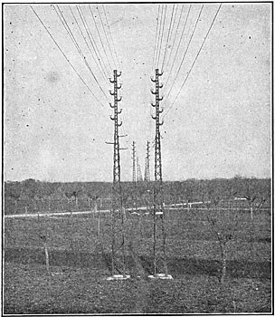
On straight lines with equal spans, the only strain to be borne by the line is exerted by the wind. In this case it is useless to employ poles of equal resistance in all directions. A line support constructed on these considerations is shown in Fig. 5. This support is constructed with two U-shaped irons, cross-connected with angle-irons. It carries six wiles divided into two sets, two metres, 6.5 feet, apart. having a very wide base, it presents a great resistance in the direction of the wind and a low resistance in the direction of the line, in which direction if is elastic and can deflect over 16 inches without exceeding the limit of elasticity, and is called the "elastic support."
 |
In the event of one or two wires breaking, the two nearest poles will bend, which will discharge the following spans; and calculations show that the entire line will stand and no injury will be done to the supports. These poles are employed for spans of over 300 feet and are very economical. In fact, an elastic support for six wires and for a span of 300 feet weighs about 1000 lb.
I shall now enumerate the principal advantages and disadvantages of iron poles.
ADVANTAGES.
DurationWooden poles will last from two to ten years, according to the nature of the ground. The durability of iron Poles cannot be definitely stated as yet, but they will surely last 40 years, reducing the depreciation to a small amount.
Large SpansSpans with iron poles may reach from 300 to 400 feet and in exceptional cases to GOO feet and more. This compensates for the higher cost of single supports, as in lieu of three or four wooden poles one iron pole can be adopted, reducing the number of insulators and consequently of weak points, and thus rendering possible the crossing of difficult passages, as shown in the examples which follow.
Lower Cost of MaintenanceThe experience with existing lines constructed with iron poles, shows that the expense of keeping the line in proper repair and good working condition is very much reduced. With wooden poles the strain exerted by the wires will slightly displace the poles or rotate the cross-arms. Dry or wet weather will lessen the connections between cross-arms and poles and between pins and poles. In some cases wooden poles will twist in time.
All the above facts affect the insulators, pins, and bindings, so that a certain amount of work is constantly required to keep them in good order.
In line-construction with iron poles, all these causes of deterioration are avoided and lines which haw. been in use from five to six years are in as perfect condition as they were when first constructed. The poles require repainting only every four or five years.
DISADVANTAGES.
A Somewhat Greater Capital InvestmentTo illustrate this point, I submit the following figures, showing the difference between a line constructed with wooden poles and a line constructed with iron poles, based upon European prices and for a three-wire line for high-tension transmission.
 |
Better Insulators Required--As a matter of fact, the breaking of an insulator means a complete grounding; but as we shall see, the insulators which can now be obtained reduce the frequency of this disturbance very much. On the other hand, it is not always true that wooden poles act as insulators as, for instance, in wet weather one cannot depend upon the surface-insulation of wood. Concluding, from an economical point of view, iron poles require a larger capital investment; but the maintenance and depreciation are reduced to a minimum. These considerations tend to make the adoption of iron poles for important transmission lines more and more general.
We shall now proceed with the consideration of the best method to be pursued in the construction of a line, more especially with reference to important lines. When the land across which the line is to be constructed has been decided upon, a careful survey is made and a map drawn, on which the location of each pole is marked, the angles and eventually the prescribed height of the lowest wire from the ground. The single supports are then studied and calculated. These are divided into two classes; namely, normal and special. The normal supports are intended for small angles, equal spans, and normal height. The special supports are those which have to meet special conditions.
Iron poles are calculated by the ordinary rules of mechanics. The forces acting on the poles are: the weight of the pole itself; the wind (both on poles and wires), and the strains transmitted by the wires. With equal spans on each side of the pole and no angles, the only forces acting on it are: the weight of the wires and the wind. When spans are not equal, there is a longitudinal strain which varies with the temperature. If an angle occurs, there is a component of the strain exerted by the wires which acts in a transverse direction. In the case of a vertical angle there will be a vertical component.
We must then begin with the calculation of the strains exerted by the wires. In doing so the effect of wind and snow must be taken into account, allowing a tension which does not exceed the limit of strain admitted for copper in coldest weather and with an overload of snow and ice. The maximum sag is also calculated in order to determine the height of the pole, as the wire must never come too near the ground. Taking into consideration all the above facts and effects, the poles are calculated in the same way as any iron structure.
We must also calculate the weight of the necessary foundation, which must be sufficient to resist the overturning moment. In this calculation the resistance of the earth surrounding the concrete foundation block is also taken into account. This having been done, the profile or ground cross-section is completed, by marking on it all the aforesaid data, including, height of poles, sag, strains, etc. The strains exerted by the wires being transmitted to the poles through the insulators and the pins, these must be considered from a mechanical point of view, and calculated in accordance therewith.
Wooden cross-arms are sometimes employed with iron poles, in which case any system of pins may be used; but in general, supports constructed entirely of iron are preferable. In this case either iron or steel pins are used on brackets composed of angle iron, as in Figs. 2 and 5, or even entirely of cast-steel, as can be seen in Figs. 1 and 4.
A special cement is employed to fasten the insulators to these brackets, or, in the case of small lines, tarred rope is employed. This differs entirely with American practice, and no attempt is ever made here to use threaded insulators, as it is difficult to obtain good insulators with thread of the exact gauge. The best cement that can be employed for this purpose is composed of ten parts of litharge and one of glycerine, well mixed.
The brackets and insulators cemented together with such a mixture form an indivisible unit, which must be replaced when?ever the necessity arises to change one or more insulators; but on the other hand, the mechanical resistance is undoubtedly much higher. In fact, in a cemented insulator the pressure between pin and porcelain is equally distributed over a large surface; while with the threaded-pin system, a slight bending causes the insulator to break, as it will in this case press against one point of the pin. The author has often tested insulators cemented on 1.5-inch rods, and always succeeded in bending the rods without breaking the porcelain.
When the span exceeds a certain length, care must be taken that the wires do not come in contact through their oscillation due to the wind. It is obvious that in order to avoid such a contingency, it is necessary that two or more wires should never be placed on the same level, and the adoption of cross-arms as practiced in America is not to be followed. In any case, it is easy to calculate the deflection of the wires from their vertical position, due to the force of the strongest wind prevailing in the country and midway of the span, thus finding the distance between the insulators to prevent the wires coming in contact.
 |
|
In the cases represented by Figs. 4 and 6 another solution is adopted: a line of six wires is divided into two sets of three wires each, one set on each side of the support and placed at a different height. Calculation shows that, if the two sets were placed at the same height, the wires would come in contact.
Fig. 7 shows a view of a line constructed following the aforesaid principles.
One may ask if it is worth while to make such a careful calculation. That is easy to answer: in order to reach a high economy in the use of iron poles, it is necessary to put in them only the quantity of iron that is absolutely necessary; and this cannot be done without a close calculation of every element of the line. The author had the opportunity of calculating the poles of a line built without much precaution, and found that each pole weighed about 200 pounds more than was necessary. As the number of poles was 600, the extra weight represented a total of about 60 tons of metal in excess of what was actually necessary.
The problem of high-pressure insulation is very carefully studied by European electricians. It is well known that glass insulators are not used in Europe and the reason for this, I believe, is that good porcelain can readily be obtained here. Glass is considered to have a better dielectric strength, but not as good surface insulation; moreover, glass is weaker against meteorological agencies, the superiority of porcelain being due to the materials composing the glazing. It must be said at once that European engineers do not consider American porcelain as good as European porcelain. It is possible that they may be mistaken, but a few tests made by the author on American insulators showed a higher dielectric resistance for the European porcelain which in appearance, finish and homogeneity of material is much better. Perhaps the difference in these particulars may have had much to do with forming his opinion.
In this connection I might mention that it is the general practice to examine all insulators on their arrival from the factory and put aside such as present a bad appearance; viz., such as are not glazed all over the surface, or that have cracks, spots, etc. This examination is performed by an ordinary workman specially trained and the pieces set aside are subjected to particularly ,severe tests. A few hundred insulators of American manufacture came over to be tested, and they were put through the usual examination. When the inspector came around, he found that all his American insulators were put to one side for surface faults. It must be said, however, that these insulators stood all the tests quite well.
The fact is that in Europe insulators may be obtained quite perfectly finished. It is considered necessary that the head and all external parts should be thoroughly glazed; to insure they are supported from the bottom in the baking process. Another advantage in favor of European insulators is that the factories are willing to make any shape desired, which facilitates the introduction of new types.
In designing an insulator the following points are to be considered: dielectric resistance; resistance against surface-arcing; mechanical strength; facility of cleaning; ease of construction.
The first two points have reference to electric qualities and an ideal insulator ought to be so proportioned that, under a certain voltage, it should break in both ways, by puncture and by surface-arcing. It is well known how the resistance against puncture can be increased, by making the insulators of several pieces, introduced one piece inside the other. In general, the different pieces are cemented together with a kind of glazing in the process of manufacture and put on the market as single pieces.
The author does not follow this practice but prefers having them furnished by the factory in separate pieces, for the following reason: when the thickness of the porcelain reaches a certain limit, the ordinary testing will not puncture a sound insulator. In testing an insulator made up of two or more pieces, one layer of porcelain may be cracked but is protected by the other layers. When the tests are performed on the single composing parts, this cannot happen, and one is sure to have the insulators made up of sound parts. Moreover, each composing part can be better inspected and the character of glazing observed. Following this suggestion many factories produce insulators in two parts, which after test are put together with glycerine and litharge cement.
Experience has demonstrated that it is useless to increase the number of component parts; up to 40,000 volts two parts are quite sufficient and above that voltage not more than three are necessary.
The ability of an insulator to resist surface-arcing is due to its dimensions and shape, the latter to be considered under a double aspect: 1. The protective action against moisture and rain; 2 The property of giving origin to electrostatic phenomena. An insulator with a very large petticoat on the top and only a second petticoat round the pin will not afford a very good protection against rain and moisture, as during a storm the inner petticoat will get quite wet. It is therefore good practice to have one or two intermediate petticoats, which will also ensure the dryness of some part of the surface in all kinds of weather. Care must however be taken not to put on too many of them, as their edges would come too near, thus forming a good path for the arc, besides increasing the difficulty of cleaning the insulator.
With reference to the influence of electrostatic phenomena. on surface-arcing it is only possible to venture some assumptions, although it appears that they have a certain basis of fact. It is well known to those who have studied tests on insulators, that the surface-arcing does not always occur at once, but seems to be preceded by a number of static discharges between the petticoats. These discharges, of a bluish color, are very marked with insulators having petticoats close together, in which arcing seems also to occur with larger air spaces. It is not improbable that these blue discharges may produce an ionization of the air and moisture, which facilitates the striking of the arc.
This would appear to be unfavorable to the introduction of intermediate petticoats, and it may be further pointed out that when a difference of potential occurs across a series of dielectrics of different specific dielectric resistances, the drop of potential is distributed not uniformly, but in proportion to the dielectric resistances. Suppose then an air-gap so arranged that the drop of potential is 1000 volts per inch and that we introduce a porcelain diaphragm, the drop of potential per inch in the two resulting air-gaps may then be higher than 1000 volts per inch. Again, as it is desirable to have a low line-capacity, an insulator with a low capacity is to be preferred. Mr. F. Carcano has lately succeeded in comparing the capacity of different insulators by a very ingenious method.
He arranged a Wheatstone Bridge with two equal capacities, a and b, a variable capacity c, and the insulator to be measured, of which we will call the capacity, x. In the place of the battery he connected a generator of electric oscillations, and in the place of the galvanometer a vacuum tube. When c is different from x the tube is bright, when by adjustment it is made equal to x, the tube is dark. By this method he was able to prove that the capacity of insulators of the various shapes used, vary from 1 to 1.9, a very large difference. The lowest capacity is shown by the insulators which have a few petticoats and one very open at the top, while the higher capacity is shown by those which have two or more petticoats close together, and more so if the outer petticoat drops and surrounds the others.
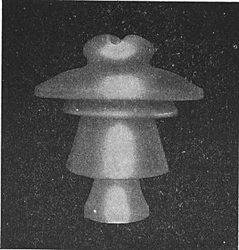
From all these facts and considerations we arrive at the conclusion that the use of intermediate petticoats is to be limited to those strictly necessary to protect the inner part from rain and to ensure that a part of the surface shall be quite dry. Insulators which are supposed to meet the aforesaid conditions are shown in the annexed photo-prints and drawings.
|
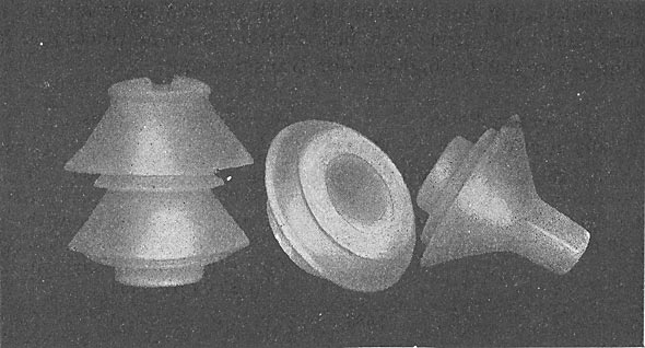
|
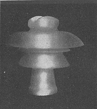
The insulator shown in Figs. 8 and 11 is composed of two pieces and is used for voltages up to 30,000 volts. The petticoats are conical and have an inclination of about 45°. The two insulators shown in Figs. 9 and 10 are composed of three pieces and are intended for 40,000 volts. All these insulators have good mechanical strength, which is also an important consideration.
|
 |
This paper which I have the honor to submit to you, shows one of the ways in which you may study a transmission line; it is a method which requires study and calculation, but the results are satisfactory, and lines constructed according to these principles are economical and, what is most important, safe in operation.
 |
DISCUSSION
(J. W. Lieb, Jr., read the paper, and in conclusion, showed a number of lantern slides embodying details of construction of Italian pole lines for power transmission.)
W. N. SMITH: It is to be regretted that the author of the paper is not present to describe in detail the practical operation of the construction shown. The author concludes his paper by saying that "the results were satisfactory," and that the lines were "economical" and "safe in operation." The methods outlined are so different from those in this country that it would seem very desirable to get in closer touch with the European engineers, and compare their results from operation with ours. A thorough discussion of details would tend to show clearly whether their methods are really an advance upon ours. The paper is an unusually valuable contribution to the cause of power transmission.
B. J. ARNOLD:There is a transmission line nearly completed in Mexico, very similar to the construction described in the paper; it is one hundred miles long, built with steel towers of the regular windmill type, using from seven to twelve poles to the mile. This is supposed to be the most modern transmission line in existence.
The New York Central Railroad Company has decided that it is safer and more reliable to have its transmission lines overhead on steel poles than to place the wires in conduits; this decision is substantiated by information secured from different transmission lines in operation in this country. Every competent engineer who was consulted, advised the company to put the wires overhead if possible, because it is easy then to locate trouble promptly and to make repairs, while if wires are underground in conduits, it is difficult to locate trouble and difficult to make repairs.
L. L. PERRY: The type of European construction illustrated in Fig. 3 would seem to have been developed largely on account of the narrow streets requiring wires to be placed one above the other. This form of construction is a poor one for making intersections; a line of twenty or so wires so set would require a pole 50 or 60 feet high.
W. S. DIX:--A disadvantage of long horizontal spans is the possibility of adjacent wires touching; the vertical arrangement of the wires would obviate this trouble. American manufacturers of insulators are now following out the lines suggested by the author, and are reducing the number of petticoats, increasing the surface, and increasing the distance between petticoats,thus reducing the arcing across. The insulators used at Shawinigan Falls have three petticoats, widely separated, and with these there has been no trouble.
W. N. SMITH:It is not clear from the figures that the three wires of a circuit are arranged at the points of an equilateral triangle. Do European engineers ignore the supposed advantage of putting three conductors at the points of an equilateral triangle?
J. W. LIEB, JR.:Several of the lines show clearly that a perfect equilateral triangular arrangement is intended.
C. F. SCOTT:There has been a great difference between engineering work done inside of the power station and that done outside of the station. The development of electric apparatus has, in general, been in the hands of a few manufacturing companies with a corps of expert engineers, who have developed the machinery to a very high degree of perfection. In general it is thought that any one can run a pole line, and the engineering of it is left to the wireman. The outside construction has been haphazard; it has been handled by many local companies with little or no consideration for engineering requirements; some of these companies have done their work well, but, in general, external construction lacks standardization, uniformity, and fails to receive the higher grade of consideration that has been given to other departments of the work.
Mr. Semenza showed the speaker through the installation in Milan, and over the Paderno pole line; this line has the appearance of solidity and of being expensive, although the figures of cost given in the paper indicate that it is not unusually high. The substantial construction of the line and the respect which is shown to railroad crossings is a thing which impresses an American. The set of downwardly-projecting fingers about halfway up the poles renders the construction fool-proof as well as mechanically substantial.
(A vote of thanks was given to Professor Ryan and Mr Semenza for their papers.)
DISCUSSION ON "EUROPEAN PRACTICE IN THE CONSTRUCTION AND OPERATION OF HIGH-PRESSURE
TRANSMISSION LINES AND INSULATORS," AT PITTSBURG, MARCH 10, 1904. BY N. J. NEALL.
The speaker wishes to call attention to some points in the American practice of to-day.
Iron Poles.The employment of iron poles for' long-distance transmission lines would probably meet with considerable opposition in some cases where the freight and haulage charges are excessive.
A 60 000-volt, 100-mile transmission plant has recently been completed in Mexico, where No. 1 B. & S. gauge hard-drawn, 19-strand copper cables have been supported with porcelain insulators and iron pins by steel cross-arms on steel towers, there being usually 12 towers per mile, normal span 440 feet, although there are some spans of 1300 feet.
The speaker has never heard in American practice that transmission wires take up vibrations in opposite directions, and he believes that the possibility of line wires swinging together would be most remote. A line consisting of three wires in triangular formation swings in unison. On the other hand, it would seem that the construction shown in the paper might cause some difficulty from wires swinging together, and even more annoyance from a wire breaking and falling on a wire below it.
Another condition which appeals to the speaker is the increased vulnerability of the metal transmission-pole to lightning disturbances. It is a well known fact that in the Western United States lightning discharges often shatter wooden poles without impairing the service. Very often, in fact, the operators are not aware that such a circumstance has arisen until the patrolman discovers this fact on his rounds. If we are to follow a highly-insulated metal-line construction, the protective apparatus must be of the highest order to relieve this line of lightning and static discharges. The most common form of lightning arrester abroad is the horn-type, which depends for its operation on the attenuation and consequent breaking of the arc after a discharge over the arrester, which takes considerable time. American practice is represented by a spark-gap or gaps between the line and ground, equipped with resistances in such a way as to cut down the short-circuiting current following a lightning discharge, and so complete the cycle of operation in a very short time. There is at present a tendency in California to try the horn-type arrester on a very large scale, but so far data concerning the worth of this type are wanting and it cannot be considered as strictly representative. Both here and abroad the horn-type arresters for the higher pressures embody some form of series resistance.
Insulators.Both in this paper and the paper by Professor Ryan, we find the crux of the transmission situation to be the insulator. In all other points, generally speaking, high-pressure operators to-day could, if it became necessary, increase the pressures were it not for the inability of the insulator to stand the increased pressure. It is not clear why the development of the high-pressure insulator has not progressed more rapidly. It may be due to the character of the materials which are considered proper for that device. These are to-day, porcelain, glass, and possibly fibrous material. A common insulator to-day for higher pressure work weighs approximately 12 pounds, and some insulators in successful operation weigh as much as 50 pounds, the latter having stood a long-continued test of 120 000 volts.
It is questionable whether glass insulators can be used for very high pressures, especially if the line should be constructed with metal towers and pins. It is perhaps known that a high-pressure condenser having glass as a dielectric will show a peculiar frosting of the glass surfaces under strain which on close inspection will be shown to arise from a tearing off of glass particles by the static stresses. The same action would doubtless arise in pole-line construction, perhaps in a lesser degree; but inasmuch as the surface of the insulator is a factor in the insulation, this deterioration might have serious results.
