[Trade Journal]
Publication: The Journal of Electricity
San Francisco, CA, United States
vol. 4, no. 2, p. 21-26, col. 1-2
The Riverside Transmission
By W. A. LAYMAN.
On December 1st last there was turned over to the municipal authorities of the beautiful city of Riverside, Riverside county, Cal., from the hands of the California Electrical Works of San Francisco, an electric transmission and general distributing system for both power and lighting, which for completeness, novelty and general efficiency typifies in every sense of the word the highest development of the art as at present understood. This undertaking, so recently inaugurated, and so successfully pursued to completion, is, however, characteristic of the community, and but exemplifies in a new direction the same spirit of enterprise and energy which has transformed so quickly and so completely, this once almost desert waste, into the paradise of luxuriant foliage, and fruit-laden orchards that it is.
| |||
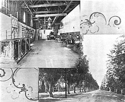
| Figures 1 and 2. - the Interior of the Generating Station and the Electric Lighting of Magnolia Avenue. |
A less progressive municipality than Riverside would probably not have attempted the transmission of electric energy a distance of twenty-two miles, and at a single step not only appropriated the energy of mountain streams for its especial municipal requirements, but also placed within the reach of all her residents electric power and light at rates against which there could be no commercial competition. And noteworthy also is it that from beginning to end no step has been taken without engineering advice looking to the employment of efficient and reliable apparatus.
Concretely stated, the system in its entirety consists of the following general features: The energy supply is purchased direct from the Redlands Electric Light and Power Company, which owns the most accessible and available water supply. The Redlands Company, by contract, delivers to the city of Riverside at the switchboard of the generating station three-phase alternating electric current of 2500 volts pressure. This current passes through step-up transformers which change the pressure to 11,000, at which the energy is transmitted 22.4 miles over the open country to a substation in the city of Riverside. Here it is in turn again transformed by step-down transformers, to a pressure of 2200 volts. From the step-down transformers it plisses to a. distributing switchboard, and from the latter continues out over the general city distributing circuits, four in number, of which two are for street arc lighting and two are for incandescent lighting and motor work. On these street circuits, reducing transformers are again used, changing the pressure to 30 volts for the street and commercial arc lights, and to 100 volts for the incandescent lights and motors. From first to last the three-phase system of distribution has been followed.
The generating power house is located at the head of the beautiful valley in which are the towns of Redlands, Colton and San Bernardino, and is quite snugly hidden away in the foothills at the base of Mount San Bernardino. This plant, the first three-phase station to be established in the West, was started on September 7th, 1893, and has earned a world-wide reputation for its unbroken record of successful operation. The generating dynamos, which are at present two in number, are of 250 kilowatts each, and are of the General Electric three-phase, 6000 alternation type. As before stated, these dynamos deliver current to the switchboard at 2500 volts. Since the two machines are not always required, there are independent sets of bus-bars, and it is from either of these or both, as the case may be, that the energy for Riverside is taken.
| |||
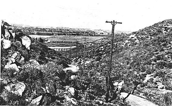
| Figure 3. - Method of Line Transposition. |
The Riverside equipment accordingly begins with a marble panel on which are mounted three double-throw, single pole quick break switches of the California Electrical Works design and manufacture, by means of which current is thrown on a special set of three bus-bars feeding the step-up transformers. From these bus-bars the current passes through a panel of specially designed single pole fuse blocks to the three 100 kilowatt step-up transformers. These blocks are so made that the portion containing the fuse is separable, and perfectly insulated so that were it desirable to do so, the fuse could at any time be quickly removed from the circuit and as easily reinserted. Furthermore the blowing of any fuse is devoid of the burning of contacts, and the block is accordingly good for unlimited service.
Coming now to the step-up transformers, there is found probably the most decided innovation of the entire equipment. These, three in number, and of a capacity of 100 kilowatts each, were built by the Wagner Electric Manufacturing Company of St. Louis, under stringent requirements for efficiency. They are a radical departure from conventional practice, each being a series combination of two 1250 to 5500 volt units, encased in cast-iron, oil filled, water-jacketed boxes. They were designed to afford not only a higher degree of insulation safety, but a more economic use of materials and a higher operating efficiency at all loads than is possible with an air ventilated transformer. The insulating oil is of the highest quality, as shown by proof tests, to be had in the market, and is sent out by the Wagner Company under guarantee. The iron cases are built up in sections, each lateral member of which is so cased as to give successive small channels confining the water to constant flow up and down as were there a continuous coil of pipe all around the transformer. The sections are cross connected in such a manner that all in all there is not possible any communication of the water and the oil. The water flow is from a gravity head of about 15 feet, and can be regulated at the will of the operator by means of globe valves in the outlet pipe of each transformer. The design is such that no cooling device whatever is required up to one-half or three-quarter load, and not until the apparatus begins to approach the full load does the temperature of the apparatus rise much above that of the atmosphere. Operating under one-third load without cooling device, the maximum temperature attained in a ten-hour run was but 100 degrees Fahrenheit.
Passing from the step-up transformers, the 11,000 volt current goes out through three single pole quick and long break switches, neatly mounted on a marble panel, to the transmission line. These switches are new, of special design, manufactured by the California Electrical Works, and are so arranged that the blowing of a protecting fuse automatically opens them. Immediately beyond the switches are the lightning arresters of the Wurtz pattern.
| |||
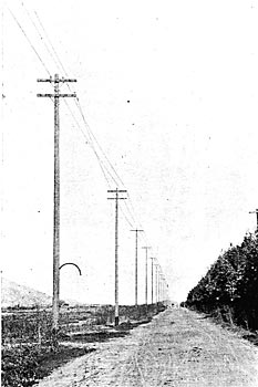
| Figure 4. - Along the Pole Line From Mountain to Valley. |
The transmission line is also an admirable feature of the system in the thoroughness and excellence of the construction. Three No. 4 bare copper conductors carry the current. These conductors are mounted on Locke triple-petticoated porcelain insulators, these insulators in turn being carried on the Locke iron pins. On the entire transmission line 3300 of these insulators have been used, and worthy of note is the fact that, aside from those mechanically injured in shipment, not a single defective one was found, nor in a single one has trouble in service subsequently developed. This statement carries no little weight with it, when to it is added the statement that there was recently experienced throughout Southern California, and immediately here in San Bernardino valley, the severest driving 'rainstorm of several hours' duration, with it an almost unprecedented amount of lightning, that has been known in years. Throughout this storm the system operated without interruption, a recommendation for the whole installation better than any guarantee that could have been given.
For several miles the transmission line is carried upon the poles of the Redlands Company. It then passes to a special pole line on which it is carried into the city of Riverside. The poles of this special portion are 30 feet in height, 6 in, top, of cedar, and 110 feet apart. The cross arms are standard, and are doubly braced. Conductors are carried 18 inches apart between centers of pills. On entering the city limits the poles are increased in height to 40 feet, for two miles, then going up to 45 feet the remainder of the distance to the sub-station.
The sub-station is a neat, although unpretentious, single-story brick building, 36 by 30 feet in size, and occupies a rather central location in the city. The transmission line enters the east side, passing directly to the high tension switchboard, which has single pole quick break switches exactly duplicating those on the high tension side of the step-up transformers. From this high voltage marble switchboard, which is about "3x4" feet, the 10,000 volt lines pass to three bus-bars, to which the step-down transformers are connected.
The step-down transformers, also of the Wagner Electric Manufacturing Company's design and build, are practically identical with the step-up transformers in general mechanical features, being oil-filled and water-jacketed. Their only difference is in the transformation ratio, and the capacity here being but 85 kilowatt units, instead of 1.50 kilowatts, as there, and having a reduction ratio of 5.
The step-down transformer secondaries lead direct to the distributing switchboard of the general wiring system of the city.
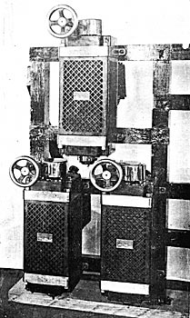
| |||
| Figure 5. - the Substation Showing Lightning Arresters, High Potential Switchboard, Transformers and the Distributing Switchboard. |
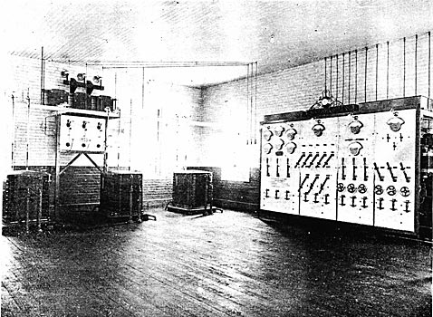
The switchboard, 7 by 12 feet, and of Italian marble, is another example of the excellent design and thorough workmanship of the California Electrical Works. The front, with its numerous single pole quick break switches and polished brass encased indicating instruments, is very attractive to the non-technical visitor, while the rear, with its systematic arrangement of connections, distributing bus-bars and neatly outgoing circuits, is equally interesting to the engineer.
The step-down transformer secondaries, on reaching the board, are grouped in three-phase, interlinking on the rear projecting studs of fuse blocks at the bottom of the main feeder panel. The current passes upward through these special fuse blocks to quick break single pole switches, thence to the Whitney indicating ammeters above, and then down to the three main bus-bars extending all the way across the board. Above the ammeters on the panel are three Whitney indicating volt meters reading through special resistance boxes direct on the full voltage on each phase of the main feeder circuit. The adjoining panel on the right is for the two three-wire arc lighting circuits. These circuits are fed from an auxiliary set of three bus-bars connected with the main bus-bars through a set of three fuse blocks and three single pole switches. Between the auxiliary bus-bars and the outgoing branches of the circuits are interposed single switches by means of which the arc load is divided up so that a small portion may be thrown on at any time. On this panel occupying a position above all the switches, is a single volt meter go arranged that it can be thrown on any two of the auxiliary bus-bars.
The third panel is for a three-wire incandescent circuit, feeding the western business portion of the city. Here again the current for each leg passes from the main bus-bar through special fuse block to a single pole switch above. Beyond the switch it passes through special pressure regulating transformers of the design and manufacture of the Wagner Electric Manufacturing Company, to the outgoing line. On this panel there is also a single Whitney voltmeter and a single Whitney ammeter. The former is so arranged through small throw over switches that it can be quickly connected to either of the three phases of the outgoing circuit. The latter is so arranged that it may be plugged by means of special flexible leads in parallel with either of the three single pole switches below, and when so connected the simple opening of the switch in with it throws the current through the instrument. By this process a single ammeter is made to do the indicating both on this panel and the next, in all branches of the two circuits.
The fourth panel is identical with the third with the exception that where the ammeter is located on the third, there is here placed the ground detector switch. This panel feeds the resident incandescent district, and on this also the outgoing line pressure is regulated by means of three Wagner regulating transformers.
The six regulating transformers are designed to control the pressure of the circuits in which they are placed for variation of 10 per cent above or below the normal feeder pressure.
The sub-station interim, as a whole, presents a very neat and attractive appearance, being well lighted and ventilated, and the apparatus is so placed as to be not only free of access, but well displayed.
The construction work of the distributing lines as they branch out over the entire city is of the same thorough character as that of the transmission line. The poles are straight and well set, the cross arms strongly braced, and the line wires all drawn up taut. These distributing circuits comprise in all over 28 miles of pole line. The arc system for street lighting is everywhere entirely independent of the incandescent and motor service system.
For street lighting there are used 80, 2000-candle power Helios arc lamps, especially built by the Helios Electric Co. for this frequency. These lamps are fed from an equal number of 2000 to 30 volt Wagner oil filled transformers. No uniform method of suspension for these lamps has been followed. Some are suspended from substantial mast arms of the design of the Western Electric Company of Chicago. Some are intersection lamps, and others are neatly mounted on wrought-iron pole top brackets.
In addition to the street arcs, numerous 1000 candle power inside Helios' lamps have been installed. These are fed from the general incandescent service, Wagner economy coils, encased in ornamental brass cases, being used to reduce from 100 to 30 volts.
| |||
| Figure 6. - Potential Regulators in the Riverside Substation. |
The incandescent service follows the conventional practice. Where requirements and conditions accommodate themselves, large transformers feed secondary bus lines, from which grouped customers are supplied. In other cases each customer is supplied from an independent transformer. The incandescent transformer service complete, as well as the arc, is of the Wagner Electric Manufacturing Company's apparatus.
A notable feature of the incandescent service is that meter service is in general use, wattmeters of the Schaefer design and furnished by the Diamond Electric Company, having been installed. These, by their extreme simplicity and reliability, are proving highly satisfactory.
The system in its entirety has been in operation four months, demonstrating through that time its success in every particular. Experts from many places have visited the city and made careful inspection, and the verdict has uniformly been that a more creditable equipment to the city and contracting engineers alike could not have been secured. Especially satisfactory to the residents of die city is the beautiful effect produced on their world-famous "Magnolia avenue." The grand drive, so charming and beautiful by daylight, is now made even more attractive at night. Clusters of three incandescent lamps, carried by neat wrought-iron brackets, are placed at intervals of 125 feet upon poles carrying the feeding circuit. This line of fire certainly produces a fine effect and well may the Riverside people feel a pride in the results achieved.
The engineering interest for the city have been conscientiously and ably handled by Mr. E. C. Sharpe, a young engineer of recognized ability all along the coast. He was engaged as superintending engineer early in the inception of the plan, and under his direction the work has been carried through to completion.
The contracting engineers, the California Electrical Works of San Francisco, have been represented in the field by Mr. A. J. Myers, under whose guidance, and after whose designs, the engineering work in every detail has been done.
The installation as originally contracted for was to have cost $40,978. Additional work will, however, bring this up to about $50,000. The Riverside Board of Trustees, to whom is due all the credit for the materialization of this elaborate and excellent system, is composed of the following representative citizens: E. F. Kingman, H. N. Bordwell, J. A. Sumers, B. Morse, S. Larue.
