[Trade Journal]
Publication: Electrical World and Engineer
New York, NY, United States
vol. 43, no. 20, p. 905-911, col. 1-2
Hudson River Power in Albany, Troy and Schenectady.
ELECTRICAL supply in Albany and Troy, N. V., is now drawn from Spier Falls on the Hudson go miles up stream, and from the falls at Mechanicville, 15 miles away. This transmitted energy is supplied to the local companies in Albany and Troy by the Hudson River Water Power Company, and the contracts call for the immediate delivery of a maximum of 6,000 hp in each city.
The water power plants at Spier Falls and Mechanicville, and the transmission lines, switch houses and sub-stations of the Hudson River Water Power Company have already been described in previous issues of the ELECTRICAL WORLD AND ENGINEER, dated June 27, October 24 and 31, and November 7, 1903.
| |||
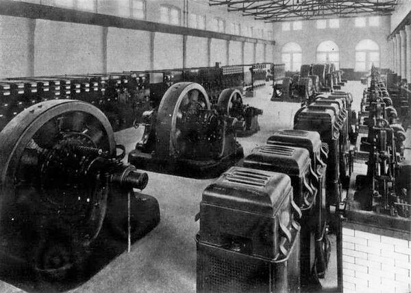
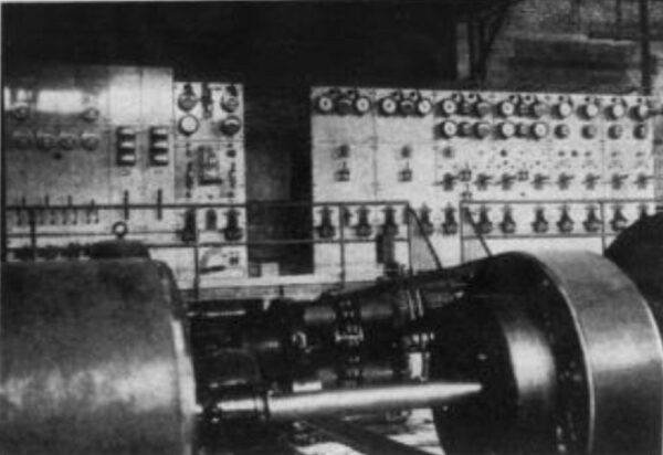
| Fig. 1. -- View of Interior of Sub-Station of Schenectady Railway, Schenectady, N.Y. |
Two three-phase transmission lines from Spier Falls, and one three-phase line from Mechanicville, run to the Watervliet sub-station of the Hudson River Water Power Company, which is just across the Hudson from the city of Troy. Each of these three circuits is made up of three bare solid copper %sires, size 3/0 B. & S. gauge. Energy delivered to the line at Spier Falls at about 30,000 volts reaches the Watervliet sub-station 35 miles away at about 26,500 volts, and the current from Mechanicville conies into the same substation at approximately 10,800 volt,. Transformers at the Watervliet sub-station reduce the 26,500-volt current from Spier Falls to the 10,800-volt pressure, and the energy from both Spier Falls and Mechanicville is then transmuted from Watervliet at this latter voltage to the local sub-stations of the lighting and traction systems in Albany and Troy. The energy from Spier Falls is reduced in pressure from 26,500 volts to 10,800 volts at Watervliet because it is necessary to cross the Hudson River with a cable in order to reach Troy, and to run underground in entering Albany. It was not thought desirable to use as high a pressure as 26,500 volts in the submarine and underground cables necessary for these purposes. At Mechanicville the current is des-eloped at a little above 10,800 volts, and the reduction of the 26,500-volt current to this lower voltage at Watervliet bring, both source, of energy there to the same pressure.
At the Watervliet sub-station the equipment includes nine transformers rated at 1,000 kw each, which are arranged in three groups for the transmission circuits above mentioned, and reduce the voltage from 26,500 to 10,800. From Watervliet two 10,800-volt, three-phase overhead circuits run to another sub-station of the Hudson River Water Power Company about four miles distant near the city limits of Albany and called the Albany sub-station. The object of this sub-station is to regulate the pressure of the two 10,800-volt circuits, connect their overhead wires with underground cables, and to reduce the voltage of a part of the energy for local distribution. This substation is 55 ft. 9 in. by 31 ft. 6 in. on the ground, partly one and partly two stories in height, and has a basement underneath its entire area. In structure the walls of this building are brick, the floor of the basement concrete, the upper floors concrete on steel I-beams, and the roof tile, also supported by I-beams.
The central portion of the basement forms an air pressure chamber over which the transformers on the first floor arc located. On this first or main floor there are also located two so-called I. R. T. automatic regulators of General Electric make rated at 300 kw each. Each of these regulators is connected to one of the 10,800-volt, three-phase circuits, has capacity to raise or lower the voltage thereon by 7.5 per cent., and is designed to maintain a constant voltage to within one-half of one per cent. Room is provided over the air pressure chamber for nine transformers of 500-kw each, these transformers to be arranges! in three groups and reduce the voltage from 10,800 to 2.300 for local distribution. From these transformers the 2,300-volt circuits lead to a switchboard on the same floor that controls the local lines. Two motor-driven blower sets occupy a part of the floor Space over the air pressure chamber, and maintain the pressure that forces air through the transformers and the I. R. T. regulators.
| |||
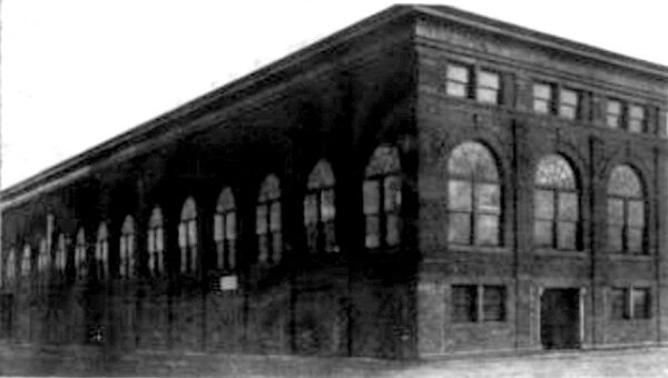
| Fig. 2. -- Dock Street Sub-Station, Schenectady |
In front the sub-station is two stories high above the basement, and the taco-story portion is 10.5 ft. wide between 12-in. brick walls and its length occupies the entire width of the building. Into this front end of the sub-station, which is this separated by a brick wall from the remainder of the building. come the bare overhead transmission lines for the entry of these line; nine circular openings, each 15 in. in diameter, were made in the brick wall along the same horizontal line and with centers 21-1/2 in. apart. These openings in the brick wall are protected from storms by an extension of the roof, which is about 2 ft. above the openings, and by a cement wall 2 in. thick and 2 ft. outside of the brick wall that drops from the extended roof of the front part of the building to the lower roof of the rear part.
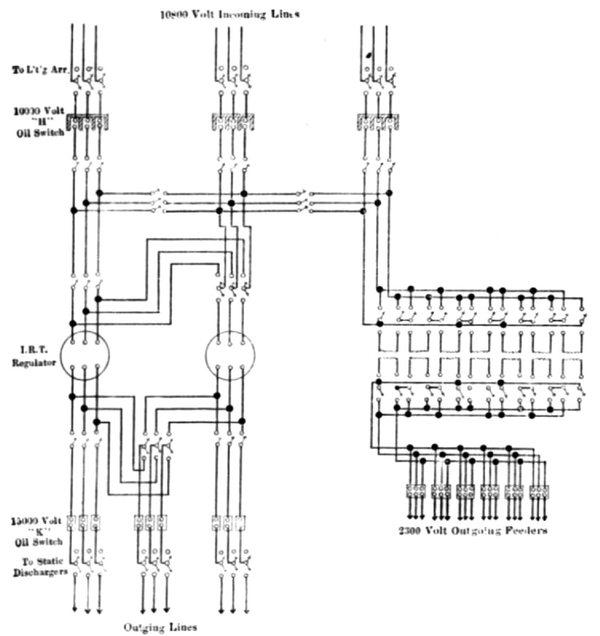
In this cement partition or wall there is a row of circular holes opposite to the holes in the brick wall, but each hole in the cement wall is only to in. in diameter. After passing through these two sets of openings the nine wires of the three transmission circuits enter single-pole, double-blade knife switches that connect each wire with a bank of lightning arresters and with a 10,000-volt type H oil switch of General Electric make. From these oil switches two of the three circuits go through other knife switches to the two I. R. T. regulators, thence through still other knife switches to 15,000-volt, type K oil switches of General Electric make, and from these K switches to more single-pole, double-blade knife switches that connect with static discharges and underground cables. The third 10,800-volt circuit, after passing through an H oil switch with knife switches on each side, goes to the transformers that lower the pressure to 2,300 volts for local distribution.
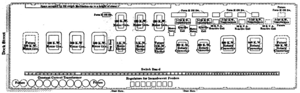 |
| Fig. 3. -- Plan of Dock Street Sub-Station |
All three of the 10,800-volt circuits, after leaving the H oil switches, connect with duplicate sets of bus-bars by means of which any one of these circuits can he joined to either I. R. T. regulator, or to the transformers. The lightning arrester cells, the static dischargers and both the types of oil switches are all located in the front end of the sub-station on two floors, and are separated from the remainder of the sub-station by the brick wall already mentioned. The conductors between these several switches and bus-bars are hare copper, and like the knife switches are supported at the tops of large porcelain insulators like those used outside on the line. Each of these insulators is mounted on a wooden pin that is o in. long above the shoulder, and that is cemented into the brick wall of the building. The clips of each knife switch are attached to a cast-iron cap that is cemented to the top of one of the insulators just named. This method of insulation is highly effective.
After leaving the K oil switches the 10,800-volt circuits connect with underground cables that run to the station of the Albany Electric Illuminating Company on Trinity Place. From the above substation of the Hudson River Water Power Company to the station of the Albany company the distance is about two miles, and twelve standard clay ducts, each 4 in. in diameter, have been laid in Portland cement concrete between these two stations. For present purposes two three-phase cables have been laid in these conduits in order to deliver the 10,800-volt current at the Trinity Place station. Each of these cables contains three 3/0 stranded copper conductors, is insulated with paper, and covered with a lead sheath 1/8 in. thick. At the station of the Albany company a new fire-proof addition has been built to receive the 10,800-volt underground cables and contain the high-tension switching and transforming apparatus. This addition adjoins the brick wall that forms one side of the main steam power station, has brick walls one story high, measures 32 ft. 4 in. by 37 ft. 4 in. outside, and has a concrete floor and a concrete cemented roof, this latter being supported on steel I-beams. A 15-ton traveling crane sweeps the entire space included within the addition save what is devoted to the switching apparatus and bus-bar compartments.
On the distribution system of the Albany company the load consists of open direct current and of enclosed alternating arc lamps, incandescent lamps on two-phase circuits, and of direct-current motors. The entire load has previously been carried by steam power at the Trinity Place station, and the plan in the application of transmitted water power in the system was to abandon the regular use of steam and yet make no changes in the character of the connected loads. To avoid any such change it was necessary to continue the operation of the 9.6-amp., direct-current arc dynamos and of two-phase, (60-cycle alternators, also to substitute rotary converters for the abandoned direct-current, 500-volt generators that had been used to carry the motor load.
| |||
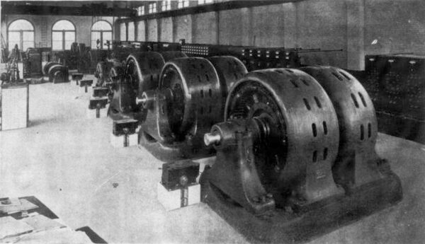
| Fig. 4. -- Another View of Interior of Dock Street Sub-Station, Schnectady. |
On entering the new addition of the Trinity Place station the two underground cables connect with oil switches and high-tension bus-bars of Westinghouse make. From these switches and bus-bars connection is made with four banks of transformers all located in the fire-proof addition to the old station. Each of two of these groups of transformers consists of three units rated at 500 kw, making 600 for the group. These three transformers reduce the 10,800-volt, three-phase current to 375 volts for a 500-kw. 550-volt rotary converter that is located in the main station. There are thus two of these converters with a combined capacity of 1,000 kw for die load of direct-current motors. Each of the other two groups of transformers consists of two units rated at Ono kw each and connected Scott fashion so as to change the current from three-phase to two-phase, while reducing its pressure from 10,800 to 2,300 volts. This 2,300 volt current passes to the switchboard for distribution lines in the main part of the station, which is separated from the transformers by a brick wall. With the 2.300-volt, 40-cycle current thus obtained the distribution circuits for incandescent lamps and induction motors are supplied.
The old station contains a long main shaft to which the arc dynamos and 6o-cycle. 2,300-volt alternators have been connected by belts in the past, the shaft itself being driven by steam power. The steam engines have been uncoupled from this shaft, though the connection can be quickly remade if it becomes desirable, but the arc dynamos and one 225-kw alternator remain belted to it. Near each end of this line of shafting and directly coupled therewith are synchronous motors, each rated at 550 kw, 10,800 volts and 343 r.p.m. These motors draw their current from the high-tension switches and bus-heirs in the new addition to the station, and the same is true of a third motor of like voltage and capacity that is direct-connected to a 225-kw alternator at each end of its shaft. This third motor and the two alternators to which it is coupled operate at 480 r.p.m., and the alternators develop two-phase, 2,300-volt, 60-cycle current. These alternators are devoted to the circuits that operate commercial, enclosed arc lamps. The transformers, rotary converters and synchronous motors just mentioned were all furnished by the Stanley Company.
Public street lighting in Albany is done entirely with open arc, direct-current, 9.6-amp. Brush lamps, and about 680 of these lamps are in use and connected to the station of the Albany Electric Illu¬minating Company. To the circuits of the company there are also connected direct-current motors of about 1,500 hp total capacity at 550 volts and arc and incandescent lamps of about 2,000 kw combined capacity on 2,300-volt, two-phase lines.
In order to reach the electric lighting station in Troy from the Watervliet sub-station of the Hudson River Water Power Company it is necessary that the 10,800-volt lines cross the Hudson River. A point about one mile down stream from the sub-station and nearly opposite to the lighting station in Troy was selected for this crossing, and a cable was laid in the bed of the river. Bare overhead conductors run from the Watervliet sub-station to the cable landing on the west bank of the Hudson, and there enter a small brick terminal house where they join the cables and have lightning arresters attached.
After crossing the river the cables enter a large manhole close to its east bank and are there connected to underground cables that run to the lighting station, a few hundred feet away. Two cables were used to cross the river, which was covered with a thick coating of ice at the time they were laid. in December, 1903. By means of horses the two heavy cables were dragged across the river on the ice so that they lay. side by side over the location on its bed, where they were to rest, which had been previously determined, and then the ice was sawed through on each side of the cables so that they sank into position by their own weight.
Each of these two cables contains three No. 3/0 stranded copper conductors, is insulated with paper, enclosed within a lead sheath, and protected on the outside by a layer of galvanized steel wires that are laid in spiral form on a bed of jute that rests on the lead sheath. Between the 3/0 wires the thickness of paper is 1/2 to 9/16 in. and between each wire and the lead sheath the paper measures about 3/8 in. This insulation was tested with 25,000 and 50,000 volts applied for one hour. The lead sheath outside of the paper has a radial thickness of 3/16 in., and then comes the layer of jute or other fibrous material, which is 1/16 in. thick, and supports the armor of No. 4 Birmingham gauge steel wires. Outside of this armor the cable has a diameter of 3-3/8 in. Both of the cables were made by the National Conduit & Cable Company.
At Troy the connected load on the electrical supply system includes about 15,000 incandescent lamps of nominal 16-cp rating, 296 enclosed arc lamps in commercial use, 427 direct-current, open-arc lamps for street lighting that are rated at 2,000 cp each, 40 open arcs for stores, and 125-kw capacity in direct-current motors. Dynamos for the operation of these several loads have been previously driven by steam power through a long main shaft at the Troy lighting station. In the application of the transmitted water power to these loads the steam engines were disconnected from the main shaft, and synchronous motors were installed to drive it and the several types of dynamos. These dynamos include direct-current arc machines of 9.6 amp., 2,300-volt alternators, and 500-volt, direct-current generators for the motor load. The underground cables bringing the 10,800-volt, three-phase current from the Watervliet sub-station enter the old lighting station at Troy, and this current, after passing through oil switches, goes to the 10,800-volt synchronous motors without transformation. In this way the old generating equipment at Troy is retained, and is driven by synchronous motors and water power instead of by steam engines.
 |
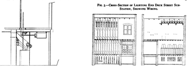
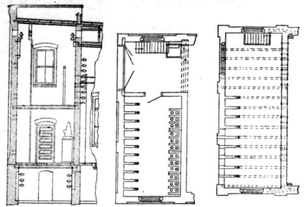
| Fig. 5. -- Cross-Section of Lighting End Dock Street Sub-Station, Showing Wiring. |
 |
| Fig. 6. -- Cross-Sectional Elevations of Cell Rooms |
Besides the supply of transmitted energy to the local lighting systems of Albany and Troy, as above outlined, the Hudson River Water Power Company also furnish a large part of the power used to operate the electric car lines of the United Traction Company in and between these two cities. Power for this electric railway system is delivered in the form of io,800-volt, three-phase, 40-cycle current at two sub-stations of the United Traction Company, one located near the Watervliet sub-station of the Hudson River Water Power Company, and the other at North Albany some four miles away. At each of these railway sub-stations the 10,800-volt current from the water power plants is transformed to about 375 volts and delivered to rotary converters that supply direct current at about 550 volts. The contracts between the Hudson River Water Power Company and the Albany lighting company, the Troy lighting company and the United Traction Company look to the complete substitution of transmitted water power for steam in the entire public lighting and street railway systems in these two cities as soon as sufficient generator capacity has been installed in the great plant at Spier Falls to meet the maximum requirements at these and other points, when operated in conjunction with the water power station at Mechanicville.
The transfer of electric lighting and railway loads in Albany and Troy to the water power system completes the substitution of energy drawn from the Hudson River for steam power in electric systems over a territory some 15 miles wide east and west, and 45 miles long north and south. This territory includes Glens Falls on the north, Troy on the east, Albany on the south and Schenectady, Ballston and Saratoga on the west. Probably no other single electric system in the United States serves an equal population over an equal area with an equal amount of power.
Transmitted water power from Spier Falls and Mechanicville also operates the electric railway and lighting systems of Schenectady, N. Y. Both of these systems are owned by the Schenectady Railway Company, and the energy for their operation is delivered through the main switchboard in the power station at the General Electric Works. Energy from steam as well as from water power is available at the General Electric switchboard, so that certainty of continuous service on the railway and lighting systems is secured without auxiliary steam equipments in its sub-stations.
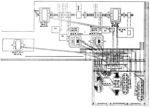 |
| Fig. 7. -- General Layout of Present Plant and New Extension, Albany. |
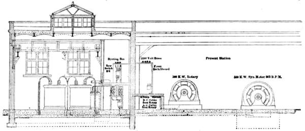 |
| Fig. 8. -- Cross-Section Through Present Station and New Extension, Albany. |
As at present operated, the railway and lighting systems have three sub-stations, one on Dock Street close to the General Electric Works in Schenectady, one at Colone on the branch of the railway that connects Schenectady and Alban), and one at Latham's Corner on the railway between Schenectady and Troy. The Dock Street sub-station distributes light and power in Schenectady, besides delivering current to the railway, but the other two sub-stations carry only railway loads. When the branch of the Schenectady railway that connects that city with Ballston Spa is in operation a fourth substation located at the latter place will supply power to that branch.
Between the power station at the General Electric Works and the new sub-station on Dock Street there are three underground cables each containing three 3/0 stranded copper conductors. Each of these cables carries 10,000-volt, 40-cycle, three-phase current drawn from step-down transformers in the General Electric plant, and the current delivered by two of the cables is devoted to railway work, while the third supplies energy to the lighting system. Front the Dock Street sub-station to that at Colone there are two circuits of three No. 1 B. & S gauge wires each. and between the Colone and the Latham's Corner sub-stations there is one circuit of three No. 2 B. & S. gauge wires. Between the Dock Street sub-station and the city limits of Schenectady the two circuits of No. 1 wire are made up of two paper-insulated lead-covered underground cables, with three conductors each, but the remainder of these circuits, and that of No. 2 wire are bare overhead conductors. These circuits running to the Colone and Latham's Corner sub-stations transmit the 10,000-volt, three-phase current delivered to the Dock Street sub-station front the General Electric Works.
When the sub-station at Ballston Spa is in operation its energy will be drawn directly from one of the two transmission circuits between Spier Falls and Schenectady, before they reach the General Electric Works. At the sub-station just named the electric railway equipment will include two 300-kw, 550-volt, 40-cycle rotary converters to operate at 800 r.p.m. three 220-kw air-blast transformers with double secondary windings, and two 45-kw air-blast reactive coils, all made by the General Electric Company. A 2-hp. three-phase induction motor will drive a direct-connected, 35-in. blower, and a 20-hp motor of the same type will operate a Magan air compressor. At the Colone and also at the Latham's Corner sub-station, both of which have been in regular operation for some time, there are three Soo-kw rotary converters supplied with energy from the mow-volt line through transformers and delivering direct current of about 550 volts.
| |||
| Fig. 9. -- Switchboard, Albany. |
 |
| Fig. 10. -- Diagram of Main Connections, Albany Sub-Station. |
 |
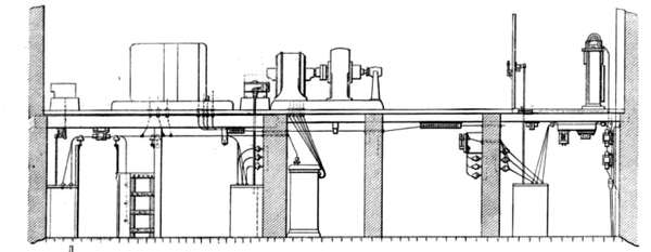
| Fig. 11. -- Section and Plans, Albany Sub-Station. |
The new sub-station on Dock Street has recently been put into service to replace an old power house and sub-station nearby and carries all of the lighting and stationary motor service at Schenectady as well as a large share of the street railway load. The ground area of the sub-station is 165 ft. 8 in. by 45 ft. 2 in., and its elevation includes a high basement and main operating room or first floor above. The basement floor of this sub-station is slightly above the ground level outside because the Hudson River and Erie Canal near which it is located arc liable to overflow. From ground to coping the height of the sub-station is 40 ft. 4 in., from basement floor to main floor the distance is to ft., and main floor to the lower cord of the steel roof trusses the distance is 24 ft. In structure the sub-station is of stone, brick, concrete and steel, save for the three-inch plank that supports the slag covering of the roof.
Up to the level of the main floor the outer walls arc of brown stone, and above this they arc brick. In thickness the stone wall is 20 in., increasing to 27-1/2 in. at buttresses, and the brick wall above is 12 in. thick, increasing to 24 in. at buttreses. The basement floor is formed by a one-inch layer of cement on 4 in. of concrete, and the main floor is composed of concrete arches resting on steel I-beams and all supported by the outer and by interior walls. The sub-station is lighted by large windows along three sides and smaller, high 'windows on the fourth and along the center line of the roof are ranged four 36-in. globe ventilators.
The basement is divided by interior walls into spaces for air pressure chambers. bus-bar compartments and oil switch cells, and all bus-bars and oil switches are located therein. Each of the to,000-volt bits-bar is located in a separate compartment of brick and concrete, and each pole of the to,000-volt nil switches has its own brick cell.
The entire main floor of the sub-station is swept by a 15-ton traveling crane, and this crane runs over an archway at one end of the budding, is here teams can drive in at the basement level. The 18-in. I-beams on the side nails of the sub-station on which the crane travels are supported by the brick abutments, and these abutments are nit reinforced by steel columns. On the main floor of the substation are located transformers, the operating gear of oil switches. rotary converters, exciters, synchronous motor-generators and the switchboard panels. Along one-half of the main floor the railway apparatus and along the other half the lighting apparatus is located Current is supplied to this apparatus in part by six transformers, each rated at 10,000 to 375 volts, and Ito kw, and of the air-blast type. These six transformers are connected in two groups with two rotary converters, each rated at 300 kw, 40 cycles and 600 volts. Two other banks of transformers are made up of six units with a rating of 10,000 to 375-volts and 220 kw each, and each of these banks feeds a 600-kw, 600-volt, six-phase. 40-cycle rotary converter. With each of the 300-kw rotary converters there is a 45-kilovolt-amp, reactive coil of the air-blast type. and with each 600-kw rotary there is a 90-kilovolt-amp reactive coil of the same type. Space has also been provided for three more 220-kw transformers and one 600-kw rotary converter with its reactive coil. Each group of three transformers is connected to the 10,000 bus-bars through a type H General Electric oil switch, electrically operated by current from a battery of 55 type E storage cells made by the Electric Storage Battery Company. The panels that carry the controlling switches for all the apparatus at the sub-station are of black enameled slate, and the maximum pressure to which they are exposed is 15 volts. Of these panels three carry instruments for three incoming lines of 10,000 volts and 4,000-kw capacity each. On each of these three panels there is one horizontal edgewise ammeter, one voltmeter of the same type, one double-pole overload relay that indicates by lamps whether the oil switches arc open or closed, one controlling switch for the type H oil switch, and a current and potential transformer and static dischargers. The two panels for outgoing lines are of 10,000 volts and 1,500-kw capacity each, and equipped like the incoming panels with the addition of polyphase induction recording wattmeters. For each rotary converter the panel includes a recording wattmeter, power factor indicator and overload relay, besides volt and amperemeters, controlling switches for the type H oil switch, indicating lamps and secondary transformers. Lamps in the sub-station may be operated from either the regular lighting circuits, the railway circuit or from the storage battery above mentioned.
Two 75-kw motor-driven exciters are already in use at the substation, and space has been provided for a third set when required The lighting equipment at this sub-station includes synchronous motor-generators and constant-current transformers. Each of three of the motor generators is made up of a 550-kw, 10,000-volt, 40-cycle, three-phase motor, and a 500-kw, 2,300-volt, 60-cycle, three-phase generator. Space for a fourth motor generator of this capacity is also provided. Each of the other three motor-generators is of 230-kw output capacity, and converts the 10,000-volt. 40-cycle, three-phase current to 2,300 volts and 60 cycles. Each synchronous motor of these motor-generators is connected with the 10,000-volt, three-phase bus-bars through one of the electrically-operated type H oil switches. Series arc lighting is provided for by eight constant-current transformers of 4,000 volts and 6.6-amp. capacity each. These transformers are supplied with 2,300-volt, 60-cycle current from the motor-generators. Current of 40 cycles was tried for arc lighting from the old sub-station, but its use has been abandoned. As may be seen from this list of equipment, the sub-station sends out only two sorts of current for the general supply of light and poster; that is, current of 60 cycles at 2,300 volts and constant-current of 6.6 amp, and the same number of cycles as the other. Two automatic regulators are provided at the sub-station for the two most important 2,300-volt circuits that leave it for lighting service, and hand regulators are connected in the other 2,300-volt lighting feeders.
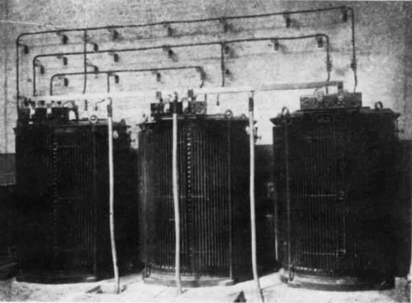
| |||
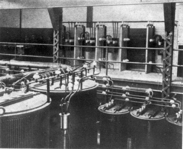
| Fig. 12. -- Transformers, Albany. |
Between the Dock Street sub-station and the main business parts of Schenectady the lighting and power circuits are composed of underground cables in Camp tile ducts. Feeder cables for the 2,300-volt circuits have three conductors each. and these conductors in most cases are each of 500,000 cm. cross-section. For the constant-current arc circuits single-conductor cables arc used. The general distribution system for light and power at constant pressure includes 2,300-volt, 60-cycle, single-phase primary mains, subway transformers in manholes and three-wire secondary mains at about 250 volts. In the outlying parts of the city the 2,300-volt underground feeder cables connect with overhead feeders, and these feeders supply banked transformers and secondary three-wire mains as far as is practicable. Separate transformers for single customers are used only in isolated 180. In candle-power these incandescent lamps range from 4 to 100, and the number of 10-cp lamps is 16,820, of 16-cp 63,769. and of 100-cp 6.
| |||
| Fig. 13. -- A Group of Transformers, Albany. |
All motors are of the induction type, and their total number is 173, with a combined rating of 671 hp, and an equivalent capacity of 11,140 incandescent lamps of 16 cp each. These motors range from 1/16 to 50-hp capacity, and there are five of the 20-hp. five of the 30-hp. and two of the 50-hp size. The equivalent rating of all the lamps and motors above named is 100,350 incandescent lamps of t6 candle-power.
Besides the above connected load the Schenectady Railway Company has secured a twenty-year contract, subject to confirmation at the end of each three-year period. to pump all of the public water supply for the city. This water is pumped into standpipes tinder a head of Ito pounds and with a suction of 6 pounds. Fur the work of pumping there have been provided two vertical turbine centrifugal pumps with a daily capacity of 12,000,000 gallons. To each of these pumps there is direct-connected an 800-hp. 40-cycle. 350-volt induction motor. Each motor is supplied with current from the 2,300-volt, 40-cycle, three-phase line through three transformers rated at 250 kw each. Two pole lines and circuits extend from the Dock Street sub-station to the pumping station, and the supply of power is assured by the fact that not only the water-driven stations at Spier Falls and Mechanicville, but also the steam plants at the General Electric Works can be drawn on. The entire electrical equipment at the Dock Street sub-station, and most of the lamps and motors on the supply system are of General Electric make. The facts as to this notable application of water power have been obtained through the kindness of Mr. A. L. Rohrer, of the General Electric Company, and Mr. F. G. Sykes. of the Schenectady Railway Company. The Schenectady system is shown in Figs. 1 to 6. The Albany system is illustrated in Figs. 7 to 13.
