[Trade Journal]
Publication: Cassier's Magazine
New York, NY, United States
vol. 26, no. 2, p. 97-121, col. 1-2
THE DEVELOPMENT OF ELECTRIC POWER TRANSMISSION
By Lewis Buckley Stillwell
IN October, 1886, in a small room on the top floor of an old house in Pittsburgh, Pa. , three hundred incandescent lamps were lighted continuously for a period of about two weeks by alternating current, transmitted a distance slightly exceeding two miles, over a single-phase circuit, comprising two copper wires of No. 4 B. & S. gauge. The potential used was 1000 volts, the frequency about 130 cycles per second, and the lamps were connected in parallel to the secondary circuits of half a dozen transformers. The ratio of transformation was 1000 to 50.
This was the first instance, in America at least, in which alternating current was used in transmitting electric energy beyond laboratory distances for the supply of translating devices connected in multiple arc. The alternator used to supply the power was driven by belt from a line shaft, to which a high-speed automatic engine was connected, and this generating plant was located in a shop of the Westinghouse Electric & Manufacturing Company on the banks of the Allegheny River within a mile of the site of old Fort Duquesne.
| |||
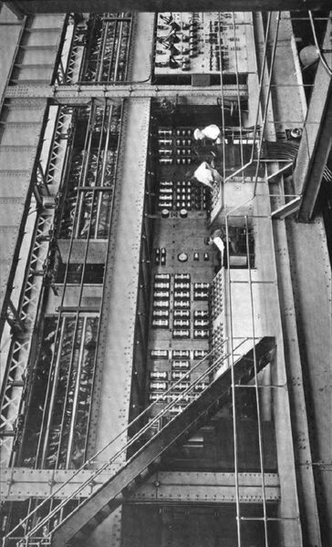
| Operating and Instrument Board of the Manhattan Railway Company, New York. |
It was the writer's fortune to be detailed to watch those lamps during twelve hours out of every twenty-four during the test,his first practical experience in applied electricity,and he vividly recalls the keen interest with which everybody who had anything to do with the work observed the results. In the history of American industrial progress the Lawrenceville test, as it has been called, was an event of no little importance. To Stanley and Shallenberger, for the technical skill and for the patient work which produced the apparatus, and to George Westinghouse, whose far-sighted enterprise realised possibilities at that time scouted by others, all those who now are deriving benefit from the wonderfully extended use of alternating currents are under an obligation which they should be glad to recognise.
 |
Prior to the Lawrenceville test, distribution of electric energy to lamps or motors had been accomplished by continuous-current systems operating at potentials of 110 to 220 volts. The three-wire system invented by Edison, permitting the use of a potential of 220 volts, was coming into use for general purposes in the larger cities, and was regarded as the highest potential available for such work. The general significance of the results of the Lawrenceville test was keenly realised; but the difficulties encountered in attempting to develop single-phase, alternating-current motors, capable of operation at the high frequency then used, practically prevented for a number of years the use of alternating current for power purposes. It was, however, rapidly developed and extensively applied in the field of incandescent lighting.
Tesla patented the polyphase alternating-current motor in 1888, but this also was slow in development, owing largely to the fact that for a long time in America efforts were principally directed toward the development of a motor adapted to the high frequency of 130 cycles per second. In 1890 the Westinghouse Company adopted as standards two lower frequencies, 60 cycles per second and 30 cycles per second. The step facilitated greatly the development of satisfactory polyphase motors, and not long afterward they began to come into commercial use.
The commercial significance of the Lawrenceville test is strikingly illustratedalthough the impression conveyed by the illustration is a somewhat exaggerated oneby the story of the manager of a gold mine in Colorado, who, in 1896, was able to operate a stamp mill located at a distance of about three miles from his water-power by alternating current transmitted to the motor over a circuit consisting of iron telephone wire of ordinary size. This was accomplished by using a high-potential single-phase alternating current. The cost of the telephone wire was about sixty dollars. It is stated that an estimate for a continuous-current plant to do the same work had been submitted by a manufacturer of continuous-current machinery, and that these plans called for the installation of copper circuits costing more than sixty thousand dollars.
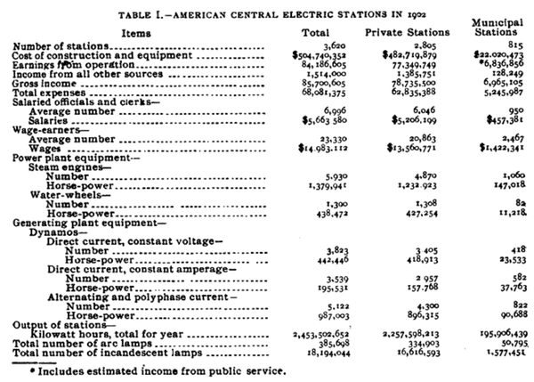
United States Census Bulletin No. 5, recently issued, places us for the first time in possession of many important and extremely interesting statistical facts relating to the use of electricity for light and power purposes in the United States exclusive of its use for traction purposes. Table I. of this bulletin cannot be improved by further condensation, and is, therefore, here reproduced.
It will be noted that of the aggregate output of dynamos installed in central stations which supply power exclusively for lighting and power purposes, which aggregate amounts to 1,624,480 horsepower, the rated output of alternating-current dynamos constitutes more than 60 per cent. A considerable number of electric power plants, installed primarily for the purpose of operating street and electric railways, also supply current for lighting and power purposes, and if these be added to those which furnish power for lighting and power purposes only, the grand aggregate of central stations becomes 3738, the number of arc lamps 419,561, the number of incandescent lamps 19,636,729, and the total income from the sale of current $90,458,420.
The relative commercial importance of the central electric station industry and gas industry is shown in Table II., which also is reproduced from Census Bulletin No. 5.
The peculiar value of alternating-current development resulting from the reduction in cost of distribution which is effected by this class of apparatus is illustrated by the fact that 75 per cent. of the central electric stations are in towns of less than 5000 inhabitants, as compared with 22.8 per cent. of the gas plants.
As regards stationary motors, the aggregate number installed is 101,064, and their aggregate horse - power amounts to 624,686. The total rated horse-power of steam engines and water-wheels used to drive dynamos is 1,772,813, of which total 77.8 per cent. are the indicated capacity of steam engines and 22.2 per cent. the stated capacity of water-wheels.
The relative number of dynamos and relative aggregate horse-power of alternators, as compared with direct-current, constant voltage machines and direct current, constant amperage machines, are shown in Table III.
It will be noted that the average alternator is a much larger machine than the average direct-current machine of either of the two direct-current classes.
It is impracticable within the limits of this article to attempt anything like a comprehensive review of the development of alternating-current apparatus for transmission and distribution of power which shall refer even briefly to the many small steps which, in the aggregate, have contributed so much to the march of progress; but in brief retrospect reference to a few of the more important steps may serve to emphasise the remarkable rapidity which has characterised the evolution of this comparatively young, but very vigorous, addition to present industrial assets.
 |
| A Full-Size Section of Three-Conductor, Paper-Insulated Cable for 11,000 Volt Three-Phase Transmission Used by the Interborough Rapid Transit Co., New York. |
In 1890 the celebrated Frankfort-Lauffen transmission illustrated and emphasised the possibilities of high-potential alternating current in bridging great distances. The potential used during the test was at times 14,000 volts, and at other times 28,000 volts; the distance was 110 miles; the amount of power was small,about 200 H. P. The transmission was in no sense a commercial success, nor, indeed, was it expected to be. It served its purpose, however, of demonstrating, upon a scale sufficiently large, the possibility of insulating a long circuit effectively for potentials very high as compared with anything previously attempted, and it also served the purpose of concentrating attention in many quarters upon the subject of electric power transmission, and so contributed in a striking and effective manner to the commercial development of a relatively new art.
In America the first important attempt at transmitting power for commercial purposes at a potential materially exceeding the 3000 volts used at Telluride, Colorado, in 189o, was the installation of the plant at San Bernardino and Pomona, in Southern California. The potential used was 10,000 volts; the distance from the water-power to San Bernardino was twenty-nine miles.
 |
| Full Size Rubber-Insulated, Steel-Armoured, Three-Conductor Cable for Submarine Work, Used by the Interborough Rapid Transit Company of New York, Underneath Harlem River. |
On May 2, 1893, Mr. George H. Winslow, engineer in charge of the plant, connected the Pomona circuit in series with that to San Bernardino and transmitted about 100 E. H. P. to San Bernardino, a distance of forty-two and one-half miles, this being by far the greatest distance attained in America up to that time.
About that time, in various shops and laboratories of America and Europe, the polyphase motor was fast taking commercial form, and at the Chicago Exposition of 1893 some striking and important exhibits of polyphase apparatus were shown in operation. Among these was a complete power transmission plant, comprising a 375-KW, two-phase alternator, an outfit of step-up and step-down transformers connected by a high-potential circuit, a 375-KW rotary converter delivering continuous current at 550 volts, a 60 H. P. synchronous motor, and a number of induction motors, ranging from 1 H. P. to 15 H. P. The system was two-phase, the frequency 30 cycles per second, and the potential of the transmission circuit 10,000 volts. At the receiving end of the line incandescent lamps were supplied through transformers, and arc lamps were fed by continuous current from the rotary converter. Continuous current from the rotary converter was also used to operate direct-current motors. The diagram on page 'co, which is reproduced from a descriptive circular published at the time, shows that this plant embodied all essential features of the latest transmission plants, except that two-phase circuits were employed instead of the three-phase plan now generally preferred. The Germans were first to perceive clearly the advantages of the three-phase system, as compared with the two-phase system, and to push the development of three-phase apparatus. Dobrovolski showed me, in Berlin, in 1890,possibly as early as 1889,a three-phase motor probably capable of developing a quarter of a horse-power. In America, Bell, of the General Electric Company, installed the first three-phase plant at Redlands, in California, in 1893.
From the autumn of 1892, to October, 1893, the officers and engineers of the Cataract Construction Company were systematically working toward a decision of the great engineering question of the best method of utilising the power of Niagara, and in the month last mentioned they executed a contract for polyphase alternating-current machinery to be installed in a central station and utilised in generating electricity to be distributed for power and lighting purposes. The decision of the Cataract Company, which had studied the subject exhaustively, both in Europe and America, had a notably stimulating effect, and less than two years later, in the Niagara power number of CASSIER'S MAGAZINE, issued in July, 1895, the late S. Dana Greene, in a very interesting article upon " Distribution of Niagara Energy," was able to list not less than seventy electric transmission plants in America in operation or under construction.
 |
To my mind, the most important events in connection with the evolution of electric transmission in America are (1) the Lawrenceville test of 1886, by which the commercial practicability of the constant-potential transformer,the key to high-potential transmission,was demonstrated; (2) the invention of the polyphase motor, patented by Nikola Tesla in 1888; and (3) the adoption, in 1893, of the polyphase alternating-current, constant-potential system as the means of distributing power from Niagara Falls.
The Lawrenceville test demonstrated the possibilities of the transformer in reducing the cost of transmitting circuits; the invention of the polyphase motor furnished the means of utilising the transmitted power for power purposes, and the adoption of polyphase alternating currents by the Cataract Construction Company for the great work at Niagara Falls sealed the commercial success of the system. An excellent meter for alternating currents had been invented and perfected by Shallenberger as early as 1888, and Elihu Thomson also had produced an effective meter for the same kind of service.
But the invention of the transformer, the motor, and the meter left still to be developed much apparatus of prime importance in the construction of the complete and effective plant for transmission and distribution of power by electricity. Switches, operated automatically or otherwise, and adapted to high-potential circuits; insulators for overhead lines and insulation for underground cables; devices for protecting apparatus against the effects of lightning,all these and other adjuncts, now deemed essential, were still in the future in 1893 so far as heavy power circuits carrying high potentials were concerned, and still in the future also was the question how best to aggregate the complicated apparatus of a transmission system,one of the great questions of engineering practice which still receives answers varying in respect to important details, but varying far less than they did ten years ago. There remained also the training of men and the development of effective organisations for operation,a work in itself requiring time, thought, and painstaking effort.
Thanks to Hopkinson, Kapp, Schmid, Brown and others, the art of dynamo design had been developed to a point where it became possible to predetermine the constants of a dynamo, and to design and build in full confidence that the results attained under test would coincide with expectation based upon calculations. The transformer, the motor and the meter placed us in possession of means for delivering and measuring power at a distance; but, as has been indicated, much remained to be done in the development of a reliable system.
 |
| Rubber Insulated, Steel Armoured, Single-Conductor Cable for Submarine Work, As Used by the Interborough Rapid Transit Co., of New York. |
It should be noted also that the development of apparatus for electric transmission thus far has been effected necessarily not with reference to fixed ultimate conditions, but with reference to conditions which are constantly changing by reason of the demand for higher and still higher potentials, and by reason of the increased complexity of circuits which results from the growth of existing plants. As the possibility of bringing greater distances becomes apparent, the demand for increased potentials makes itself felt, and every important increase of potential implies corresponding increase in insulation of circuits, including transformers, switches and all devices connected therewith.
Again, as a given power company extends the sale of its product, every additional user of power implies additional apparatus connected to the circuits and increased risk of interruption of the general supply of power to customers of the company. Increase of potential must be met by improvement in insulation, and interruptions due to aggregate length and complexity of an interconnected system of conductors must be met by improvement in automatic circuit-breaking devices, arranged with reference to the location of interruptions of service due to failure of insulation or other causes. The fact that during the past ten years the rate of interest upon capital has been decreasing in America has, doubtless, tended to lessen in some degree the force of the argument in favour of a rapid increase in potentials adopted for new plants; but the reasoning which is brought to bear upon such questions as the selection of potential too often has little connection, or at least little conscious connection, with such matters as a progressive fall in rates of interest.
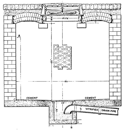 |
| Cross Section of A Cable Manhole of the Manhattan Division of the Interborough Rapid Transit Company, of New York. |
A subject that has received less attention than it deserves is the difficulty of maintaining an uninterrupted supply of power to the motors, lamps, and other translating devices used by customers which results from increased lengths of conductors and increased numbers of translating devices connected to a single source of supply. Electrical engineers are not accustomed to enlarge upon the subject of interruptions of service, but the first step in the correction of defects is recognition of their existence, and reference to this phase of the general subject may be useful.
Obviously, interruptions of service may have their origin in the power plant, in the transmitting circuits, or in apparatus located upon the premises of the user. Other things being equal, those due to line troubles will vary with the length of the line, as has been clearly recognised since the earliest days of transmission. Equally obvious, but apparently less clearly recognised, is the fact that a plant delivering power to a dozen users over a line of equal length faces an increased risk of interruption of service by reason of the addition of a number of branch circuits at the receiving end of the line, and connection to the system of a dozen outfits of apparatus in users' premises in place of one. Where it happens necessarily, as at Buffalo, at Milan, and at a few other places, that a very considerable number of users are supplied through cables placed underground, which cables, in turn, receive through transforming stations their supply from overhead transmitting circuits extending across country from the water-power, the difficulties in the way of maintaining an uninterrupted supply of power become very serious.
Imagine, if you please, that in a given city a score of separate steam engines are used to drive line shafts in twenty factories and mills. Each of these engines is liable to a certain number of accidental interruptions of service, averaging, perhaps, one per annum. If, for the twenty steam plants, twenty electric motors, supplied through an inter-connected system of conductors, be substituted, it is evident that effective means must be adopted to prevent an accident to one motor, resulting in interruption of service in the twenty factories and mills; otherwise if accidents causing interruption average the same with motors as with steam plants, each user will suffer from twenty interruptions per annum instead of from one.
It may be noted still further that the user who philosophically bears with an interruption caused by apparatus owned by himself is usually far from philosophical when inconvenienced by interruptions of service due primarily to failure of other people's machinery The reasons for adopting effective means for preventing interruptions of service, therefore, increase in a ratio greater than the increase in number of users.
Unfortunately, the complete solution of the problem cannot be found in the adoption of the fuse or safety-link, which is generally and satisfactorily used in dealing with the similar problem which arises in supplying lamps and motors connected to the great direct-current networks in the large cities, since in such cases as that of Buffalo the distances involved in the local distribution are so great as to make the use of high-potential circuits to more than one transforming station imperative, and with circuits conveying alternating currents at 10,000 volts or even at 2000 volts ordinary fuse strips are altogether inapplicable, while nine-tenths of the special devices which have been proposed to take their place are equally useless.
The problem is made still more difficult by the phenomena of resonance and so-called electric surging, the latter of which always follows a sudden disturbance of potential of the system, while the former, under certain conditions of capacity, inductance, and frequency, is liable to develop potentials capable of breaking down the most perfect insulation available at the present time. Obviously here is a fine opportunity for the exercise of skill, sound judgment, and perhaps even inventive ability upon the part of the engineer who lays out a system of high-potential alternating-current distribution destined to supply power at some future time, if not at the outstart, to a large number of users distributed over territory too extensive to be reached by direct current.
The first thing to be done is, of course, to secure throughout the system the most perfect insulation that is practicable. Could the insulation be maintained perfect in all parts, nothing more would be needed. This, unfortunately, is not the case, and it becomes necessary, therefore, to lay out such a system of distribution with the greatest possible care, adopting effective means for localising the interruption which can result from a failure of insulation in any part of the system.
Much has been done since 1893 to overcome the difficulties faced by the companies which first ventured into the field of polyphase transmission and distribution, but there is still room for material improvement. The insulation of cables has made wonderful progress, as have also glass and porcelain insulators for overhead lines, although the quality of American porcelain is not yet equal to that of European porcelain used for the same purpose.
 |
| Type C and Type E Insulators Used by the Niagara Falls Power Company. |
The time-limit circuit-breaker, intelligently applied, is of great value in lessening the evil consequence of failure of insulation by localising the resultant interruption of service; but the reversed current circuit-breaker, first used by Andrews, at Hastings, England, which should be an equally valuable adjunct to a transmission plant, is not yet available in thoroughly satisfactory form. The extraordinary development of the oil switch in recent years in America, following, but quickly surpassing, European practice, has furnished an effective solution to many of the vexing questions of switchboard practice which caused so much trouble a few years ago. The insulation of dynamos to-day is such that the generation of currents at 11,000 volts is effected with a factor of safety equal to what was possible ten years ago with generated potentials of 2200 volts, and the advance in construction of transformers is almost equally striking.
In large plants the general adoption of the method of operating switches in the power circuits at a distance from the operator by means of compressed air or electricity, insuring safety of the operator, has resulted in great gain in certainty of operation. To this end also have contributed a number of valuable auxiliary devices, such as the ingenious and effective synchronism indicator invented by Mr. Paul M. Lincoln, the diagrammatic arrangement of control switches, which places under the eye of the operator at all times an accurate diagram of connections existing throughout the system, various improvements in regulating and governing mechanism of engines, and more particularly of hydraulic turbines, and, most important of all, perhaps, the development of devices for the protection of electric apparatus against the effects of atmospheric electricity.
 |
| Porcelain Insulators for High-Potential Circuits. |
It may be interesting to refer briefly to some of the more important of these improvements of the last decade. As regards means available for transmission, the most striking development is the rapid evolution of cables insulated by paper, treated with resinous oils.
They are necessarily lead-sheathed to protect the insulation against moisture, and if the sheath be preserved and the cables be not operated at temperatures exceeding 80 C. degrees, there appears to be no reason to doubt their durability. In the city of New York, the Manhattan division of the Inter-borough Rapid Transit Company now has in use upwards of 120 miles of cable of this character, operating at a potential of 10,500 volts, and during the last nine months there have been only two failures of cable insulation, one of which, however, did not cause any interruption of service.
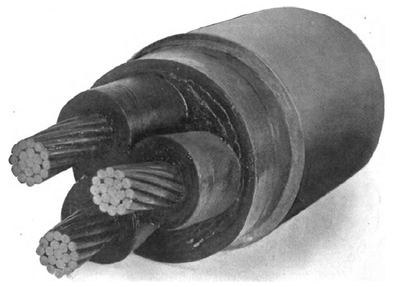
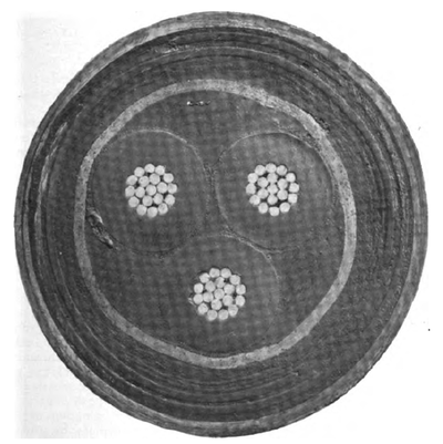
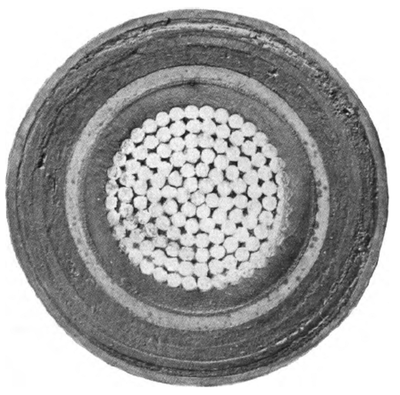
At St. Paul, Minnesota, the gas light company has, for the past four years, successfully operated cable of this kind under a potential exceeding 20,000 volts, and recently in developing plans for an important transmission project I have received from two reliable manufacturing companies quotations upon paper-insulated cables guaranteed for service under a potential of 33,000 volts, alternating. There is no reason to doubt that cable of this type, constructed under proper specifications and with sufficient care may now be considered thoroughly reliable for commercial service under such potentials as these, provided proper precautions are observed in the arrangement of circuits and in the installation of protective devices to prevent such cables being subjected for any appreciable length of time to potentials materially exceeding the working potentials for which they are intended. The illustration on page 102 shows the construction of three-conductor cable as used by the Interborough Rapid Transit Company for 11,000-volt, three-phase distribution in ducts.
The illustrations on pages 103 and 105 show, respectively, cross sections of three-conductor, rubber-insulated steel armoured cable and single-conductor, rubber-insulated, steel-armoured cable, as used by the same company in submarine work.
| |||
| A Motor-Operated Oil Switch for 11,000-Volt Three-Phase Circuits, Made by the General Electric Company, Schenectady, New York. |
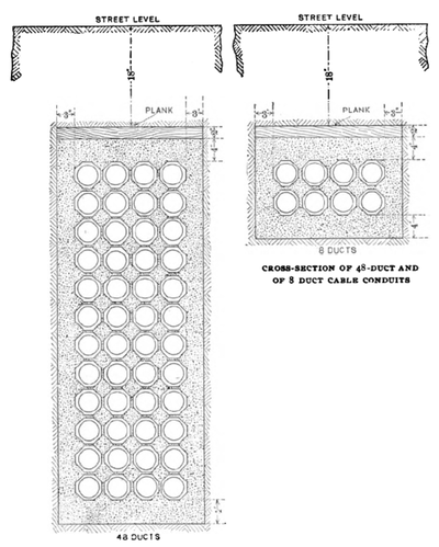
Methods of laying cables also have greatly improved. In the United States they are now usually laid in tile ducts, set in concrete. Much of this duct work is still badly done, particularly with reference to the dissipation of heat, due to currents traversing the cables; but general practice in this respect has improved greatly within the last two or three years. The illustrations on pages too and Job show, respectively, a cross-section of a cable conduit and a cross-section of a manhole as used by the Manhattan division of the Inter-borough Rapid Transit Company.
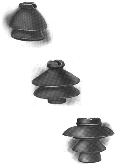
Insulators for overhead lines have been very radically improved since 1893. The insulator used in the Frankfort-Lauffen transmission employed an oil cup to decrease surface leakage. Dust and other material, accumulating upon the surface of the oil, destroy its insulating value, and this type of insulator is, therefore, not now used commercially. The 10,000-volt plant at Pomona and San Bernardino, California, installed in 1890 and still in successful operation, uses a double-petticoat glass insulator designed by Morris, of the Westinghouse Company, and the writer, and in 1895 this insulator was successfully used by Mershon during the high-potential tests which he conducted at Telluride, Colorado, under a potential of 45,000 volts.
The so-called "Type C" insulator, as used by the Niagara Falls Power Company upon the first pole line, erected between the Falls and Buffalo, and the "Type E" insulator, as used upon the second pole line, erected in 1900, are shown in section on page 108. The former was particularly defective in respect to its mechanical attachment to the pin, which was but 7/8 inch in diameter at the top, while the number of screw threads engaging pin with insulator was but six. The pin used with the "Type E" insulator is 1 1/2 inches in diameter at the top, and nine threads secure the insulator to the pin. The Niagara Falls Power Company increased the line potential between Niagara and Buffalo from 11,000 volts to 22,000 volts in the spring of 1901, and since that time has been replacing gradually the "Type C" insulators on the old line by insulators of the newer type, which have been very successful.
On page 109 are shown illustrations of three insulators. The smallest is "Type E," as now used at Niagara, while the largest is an insulator made by the Locke Insulator Manufacturing Company, of Victor, New York, for very high voltage. This insulator has been selected for the 110-mile transmission plant of the Guanajuato Power & Electric Company, in Mexico, which company is now using successfully a potential of 60,000 volts. The insulator of intermediate size is one which the writer designed several years ago for line potentials of from 40,000 to 50,000 volts. It is the largest porcelain insulator made in a single piece, the Locke insulator being made in several concentric materials or cups which are cemented together. Many other insulators effective for line potentials up to 50,000 volts are now available, and some of the more recent of these are designed for pins of adequate size.
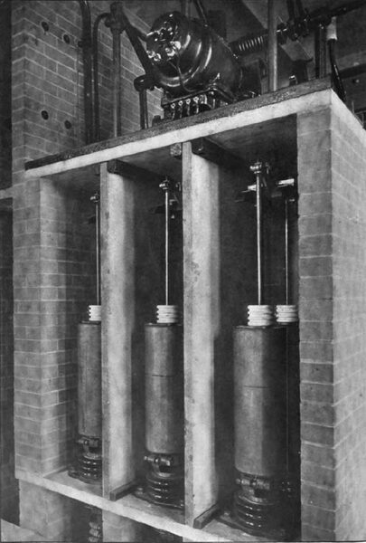
Probably the most valuable single addition to apparatus developed since 1893 for high-potential transmission is the electrically-operated oil switch. The illustration on page Ito gives an excellent idea of its construction, as built by the General Electric Company, of Schenectady, New York, for 11,000 volt, three-phase circuits.
| |||
| Lincoln Synchronism Indicator As Used by the Niagara Falls Power Company. |
Two breaks are provided for each of the three sides of the circuit, and in opening the circuit the break is made under oil contained in large metal cylinders. Each cylinder contains a fixed terminal. When the switch is closed, current passes from one terminal of each pair to the other through two vertical rods of copper connected at their upper ends. The switch parts belonging to each of the three sides of the circuit are separated from all other parts of the switch and its mechanism by being enclosed in a brick compartment with vertical partitions of soapstone, as shown in the illustration. The moving parts of the switch are operated by mechanism located upon the top of the brick compartment, this mechanism being, in turn, actuated by an electric motor which is controlled by circuits extending from the control board, or pilot board as it is sometimes called. At the control board the operator has before him a small switch, sometimes two, corresponding to each of the large three-phase switches, and the movements of the latter are controlled by opening and closing the former.
The plan of opening and closing switches located at a distance from the operator by compressed air or electricity was first adopted, I believe, by the Westinghouse Company in connection with the switch gear installed in the first power house of the Niagara Falls Power Company. In that plant the plan demonstrated its value, and it is now generally and in fact almost necessarily adopted in the case of all large modern plants. The sense of security enjoyed by the operator while controlling these great switches at a distance results in confidence which goes far to ensure that precision which is so absolutely essential.
At the Manhattan Railway power plant in New York City sixty-six switches of this type are installed, and, on the average, have been in use about eighteen months. During that time not one of these switches has failed to operate as and when expected, and while some of them have been called upon to open automatically circuits in which extremely heavy short-circuited currents were flowing, they have done this without damage other than some spilling of oil from the oil cups.
The illustration on page 112 shows a synchronism indicator as installed upon Switchboard No. 1 in Power House No. 1 at Niagara Falls. This synchronism indicator, invented by Mr. Paul M. Lincoln, is an ingenious and most useful adjunct to a power plant using alternators. When an alternator is to be connected in parallel to bus bars supplied by one or more alternators the synchronism indicator is connected to the circuits through suitable transformers and becomes a perfect guide to the operator. The index arm of the indicator revolves at a speed proportional to the difference in speed between the alternator to be synchronised and the alternators supplying the bus bars, and it shows also which of the two is running at the higher speed. As used at Niagara, it is of very large size, and is mounted upon a vertical shaft which makes it possible to turn the face of the instrument so that it becomes visible not only to the operator upon the switchboard who throws the switches, but also to the governor attendant upon the floor who is adjusting the speed of the alternator preliminary to the operation of synchronising.
 |
| Alternator Controlling Bench Board Used by the Manhattan Railway Company, New York. |
 |
| Alternating Current Feeder Controlling Bench Board Used by the Manhattan Railway Company, New York. |
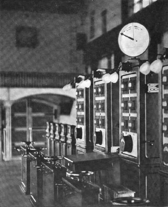
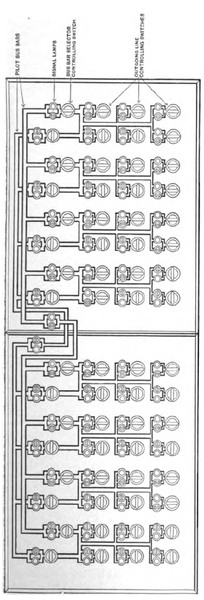
Still another comparatively recent auxiliary of value in the operation of large plants is the diagrammatic pilot board illustrated on pages 114 and 115. In this arrangement of the operating switches which control the power switches at a distance, dummy bus bars and other apparent (but not real) connections are provided and assembled in connection with the operating switches in such a way as to place before the operator at all times a diagram of the existing connections of the power circuits. Every time he changes the position of the pilot or control switches he alters the diagram to conform to the resulting connections of the power circuits, the diagram as indicated to the eye by handles of the pilot switches being corroborated by red and green signal lamps, one or the other of which is lighted when the corresponding power switch reaches the end of its travel in the movement incident to opening or dosing the circuit. The illustrations on pages 114 and 115 show the diagrammatic pilot board and the instrument board as used for controlling the operation of eight 5000-KW alternators at the Manhattan power plant.
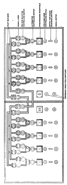
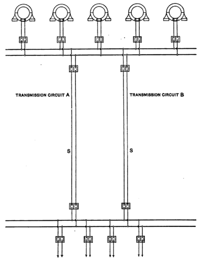
The development of the oil switch, which is capable not only of reliably making and breaking circuits in ordinary operation of the plant, but also of opening circuits traversed by short-circuiting currents as a result of failure of insulation, opens the way to the effective use of the time-limit relay attachment and of the reverse current relay attachment for such switches used as automatic circuit-breakers. The respective functions of these two relay attachments can be described best by reference to the diagram on page 116.
This diagram shows the essential connections of power circuits in a power plant comprising five alternators and transmitting power to a sub-station through two cables or overhead circuits. To simplify the diagram, the arrangement shown is that required for a single-phase apparatus, and but one set of bus bars is shown in the power house and also in the sub-station. From the substation four circuits serve to distribute power at low potential. If no time-limit circuit-breakers be used, a heavy short-circuit upon one of the distributing circuits from the sub-station may result in opening not only the circuit-breaker or fuse located in the sub-station to cut off the particular circuit affected, but also the circuit-breakers or other devices located at the power house and intended to cut off one or the other of the transmission circuits in case of a heavy short-circuit between power house and substation.
Instances have been known where even the automatic circuit-opening devices between dynamos and bus-bars have been opened as a result of a short-circuit beyond the transformers in the sub-station. If the time-limit relay be used in connection with the circuit-breakers, and if it be set, say, for three seconds in the case of circuit breakers between dynamos and bus-bars, one second in the case of circuit-breakers in the transmission circuits at the power house end of the line and for instantaneous operation in distributing circuits from sub-station, the circuit-breaker in the distributing circuits at the sub-station may be relied upon to open before those in the transmission circuit at the power house, and, of course, also before those in the dynamo circuits at the power house can open. The interruption of service, therefore, which results from failure of insulation in one of the distributing circuits from the sub-station will be limited to the supply of power through the particular distributing circuit affected.
The reversed current circuit breaker, which should be an equally valuable adjunct to a transmission plant, unfortunately, as has been said, is not yet available in thoroughly satisfactory form. Andrews used it between alternators and bus-bars for the purpose of cutting out an alternator which might become short circuited. It is equally applicable, of course, to alternating-current circuits between a power house and sub-station, provided the circuits are connected in multiple with each other at both ends of the line.
Referring again to the diagram on page 116, we may imagine that a short-circuit occurs on a transmission circuit, designated A, at the instant of maximum flow of current in one direction, which, for convenience, we may call positive. It is evident that the instant the insulation between conductors of circuit A is broken down, e. g., at point designated S, current will flow from the bus-bars at the power house and also from all bus-bars at the sub-station toward the point S. This implies a reversal in the direction of flow of current between the bus-bars at the sub-station and the point S, as compared with its direction at the instant had no short-circuit occurred. This reversal may be utilised to open the circuit breaker by actuating a relay device.
Practically all of the reversed a current relays thus far tried in the United States have proved unsatisfactory by reason of the fact that they require a potential in phase with bus-bars at sub-stations, and in case of very heavy short-circuits this potential usually drops below the limit effective for operation. The required potential might be obtained from a small alternator, normally operated in synchronism with the power supply and equipped with a fly-wheel of sufficient size to keep the alternator going at synchronous speed for the necessary fraction of a second after the occurrence of the short-circuit, or perhaps better means might be devised for accomplishing the same purpose.
 |
| Typical Diagram Illustrating Use of Time Limit and Reversed Current Circuit Breakers. |
Where three or more circuits between power house and sub station are available, reversed current relays can be operated by difference in current flowing through the short-circuited line and the other lines, and relays of this type are now upon the market.
Without entering further into discussion of details, it will be evident that proper use of the time-limit relay and of the reversed current relay, in combination with the oil switches now available, afford means for effectively localising the troubles resulting from any short-circuit in an interconnected alternating-current system of distribution which is carefully laid out with a view to such localisation.
Perhaps no adjunct of a successful transmission plant employing overhead circuits is more important than the lightning arrester, and in the development of none has more remarkable progress been made since the days immediately following the Lawrenceville test. For this progress we are indebted chiefly to Alexander J. Wurts. The first alternating-current plants in America used the brass "saw tooth" arrester which was then in general use by the telegraph companies. Bitter experience soon demonstrated the futility of this device when applied to 1,100-volt, constant-potential circuits, supplied by dynamos having low internal resistance, and it was soon displaced by a flood of ingenious and more or less effective arresters, which, in turn, were effectively superseded by the so-called non-arcing metal arrester discovered by Wurts in 1892. The problem was to provide an easy path from conductor to earth for static electricity due to lightning and to prevent the dynamic current following in the path of the static discharge and short-circuiting the system. This, for potentials up to about 25,000 volts, has been effectively accomplished by means of the non-arcing metal cylinders. For higher potentials, the performance of lightning arresters is not yet altogether reliable. The illustration on this page 290 shows a modern lightning arrester outfit for a 25,000-volt circuit. Detail descriptions have been printed in various technical journals and in advertising publications of manufacturing companies.
| |||
| A Lightning Arrester for 25,000-Volt Alternating Current Circuits. |
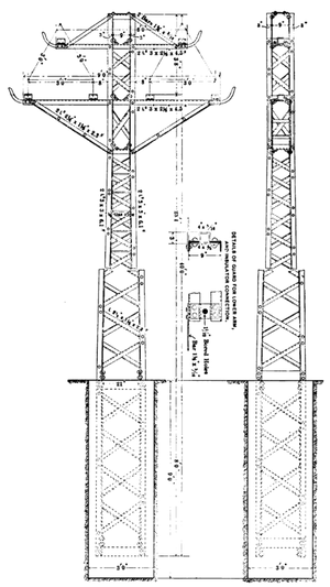
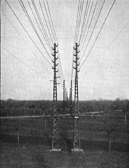
As regards line construction, it is to be regretted that few plants in the United States up to the present time have erected transmission circuits which, from the standpoint of permanence, compare favourably with approved European practice as illustrated, for example, in the illustration on page 120, showing the steel pole line used between Paderno and Milan. For this illustration I am indebted to Mr. Guido Semenza, the very able engineer of this important and interesting plant. Nearly all pole lines in America are of wood, and, so far as insulation is concerned, there is much to be said in favour of this material. In my opinion, however, the lines of the future will use steel poles or towers, widely spaced, and will rely for insulation exclusively upon the insulators to which the conductors are attached. The idea of using steel poles is not new in America.*
* Since this article was written, the writer has been furnished through the courtesy of Mr. Henry Hine, president of the Guanajuato Power & Electric Co., Mexico. with a description of the steel tower construction adopted by that company, which marks a most interesting and important advance in the art of electric power transmission in America, not only by reason of the substitution of steel towers for the usual wooden poles, but also because of the long spans used. Further reference to this remarkable example of modern line construction will be made in a future article.
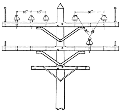
The illustration on page 118 shows a design for a steel pole carrying two transmission circuits, as designed under the writer's direction in 1894 by the Pittsburgh Bridge Company and submitted to the Cataract Construction Company with reference to the then proposed transmission from Niagara to Buffalo. It will be noted that the three conductors of each circuit are triangled, the sides of the equilateral triangle measuring 36 inches.
 |
| A 40 Foot Steel Pole Designed by the Pittsburgh Bridge Company. |
Unfortunately, this plan was rejected, and the first pole line carrying two circuits was erected between Niagara Falls and Buffalo in line with the plan illustrated on this page, both circuits originally being carried upon the upper cross-arm, the three wires constituting each circuit being spaced at intervals of 18 inches and carried at the same level as shown at the left.
This arrangement was a great temptation to mischievous boys, who threw wires and sticks across the line wire. Owing to the position of the conductors they inevitably came in contact with at least two sides of the circuit, causing tremendous short-circuits, which blazed along the line until the power was cut off. The light of these short-circuits in some cases was seen at a distance of a mile, and unless the power was cut off at the power house they inevitably resulted in burning off and dropping the conductors of the transmission circuit. The triangular arrangement of conductors illustrated on the right hand side of the drawing on this page shows the location of the conductors of the first two circuits as subsequently located. In this position they have given little trouble.
 |
| Position of Insulators on the First Niagara-Buffalo Pole Line. |
Enough has been said to show that engineers who today are designing electric power plants have available for use much highly important, if not absolutely essential, apparatus which did not exist ten years ago. Efficiency of dynamo, transformer, and motor has improved since then, but it has gained little as compared with the development of such auxiliary apparatus as has been referred to here. The latest dynamo installed at Niagara is not materially more efficient than the first one which was put into commercial operation there in 1895; but line insulators, cable insulation, switches, and relay devices for automatic circuit-breakers are incomparably superior to any that existed at that time.
Doubtless further improvement in respect to details of construction is to be expected, but the apparatus available to-day is such that transmission at 60,000 volts should be more reliable than transmission at 6000 volts was ten years ago. Accurate and extensive knowledge and sound judgment the engineer who designs and installs such a plant must have, but the materials are now available if he knows where to find and how to use them.
Considering the probabilities of future development of electric transmission, it is reasonable to expect that the utilisation of water-powers will continue until practically all of any considerable magnitude are put to work. The ability to employ higher potentials means ability to span greater distances, and thus markets will be found for water-powers which hitherto have been deemed too remote from industrial markets for profitable utilisation. Improved reliability and gradually lessening cost of apparatus will co-operate influentially toward this result, as will also the decrease in rates of interest upon capital which has been so marked in recent years.
| |||
| Steel Pole Line and Circuits on the Milan-Paderno Transmission, Italy |
It is to be expected also that power plants using steam or gas engines to drive dynamos and distribute power electrically over large districts will be constructed. Recently in Great Britain a number of corporations have been chartered with this object in view. Some of these plants are now under construction, and the commercial results of their operation will be of great interest. So far as I am aware, nothing of this kind on a large scale has been attempted up to the present time in America; but there are undoubtedly districts where such enterprises should be profitable.
The opportunity for profit rests chiefly upon three facts:(1) that power can be produced more economically by a very large steam plant than by a small one; (2) that the aggregate power which a central station plant, supplying a certain district, is called upon to develop at any given time is very much less than the sum of the maximum outputs of the small plants required to do the same work; and (3) that an electric motor occupies much less space and requires less attention than a steam plant. A 50,000 horse-power steam plant, supplying electric power for general purposes to a district having a radius of fifty miles, will burn about 3 lbs. of coal per average kilowatt-hour delivered throughout the district, while the average consumption of coal by the steam plants which such a central power plant would displace is usually not less than 10lbs. per kilowatt-hour.
As regards ratio of the maximum output of the central station to the sum of the maximum outputs of the displaced small plants, definite generalisation is impossible, because everything will depend upon the kind of work done by the small plants. I think it safe, however, to say that this ratio will rarely, if ever, be higher than 2 to 3, and in some instances which have come under my observation it is as low as 2 to 3. In other words, a 50,000 horse-power central station plant will rarely, if ever, fail to do the work of small plants aggregating 75,000 horse-power, and in some instances will be capable of doing the work of small plants aggregating 150,000 horse-power.
Transmission of power from coal fields to large cities works out much less favourably, since in this case it must compete with the alternative plan of transporting the coal to the city or to a point near it and there generating electric power in a steam plant equally economical and equally deriving the benefit which results from the fact that a single large plant can displace a large number of small plants whose aggregate output considerably exceeds its own. In this case, the plant located at a distance from the city must be larger by an amount equivalent to the maximum losses in transmission, and the fuel burned for a given delivery of power in the city will exceed the amount which would be burned if the plant were located in or near the city by an amount proportioned to the average square of the power transmitted.
Generally speaking, the difference in the cost of coal delivered to a plant in the city and the cost of coal delivered to a similar plant located in the coal fields at a distance of 250 miles from the city will not represent as much as 10 per cent. upon the difference in annual cost of the two plants thus respectively located, and when we take into account the possibilities of interruption of service in the case of the plant located at a distance, it appears evident that in the present state of the art of transmission, the better plan is to locate the central station near the city and pay the cost of transporting the coal to the point.
But what may prove to be the greatest of all fields for alternating-current transmission now confronts us in the application of electricity to the operation of railways. The successful substitution of electricity for steam by Ganz & Co., of Buda-Pesth, upon the Valtelina line, in Italy, by which a great economy has been effected in cost of operation of a railway more than sixty miles long, is an object lesson of great significance. Freight as well as passenger traffic is handled successfully under very severe conditions of grade, curvature, and climate, and the economy resulting from the substitution of electricity for steam challenges the attention of railway managers and engineers.
The recent high-speed trials at Zossen, Germany, in which a fifteen-ton car, operated electrically, attained a speed exceeding 131 miles an hour, invite attention in the same direction, and the development of two single-phase, alternating-current motors in America and of two similar motors in Europe, each of which is stated to meet effectively the requirements of railway service, mark by far the most interesting and important practical step of this new century in the use of electricity for power purposes.
