[Trade Journal]
Publication: Electrical World and Engineer
New York, NY, United States
vol. 43, no. 26, p. 1187-1189, col. 1-2
Bear River Power Plant and Utah Transmission SystemsII.
(Concluded.)
FROM the power house the three-wire transmission line passes up the east bank of the river and skirts the base of the Wasatch Mountains, keeping for the most part above the cultivated farms. It taps into the Utah Light & Railway Company's line at Ogden. The total transmission distance from the power house to Salt Lake City is 82 miles and the route of the line is shown on the map, Fig. 17, to which reference will be made later.
The transmission line consists of three No. 0 soft-drawn copper wires, carried on 40-ft. round cedar poles set 120 ft. apart. The insulators are carried on two cross arms, as shown in Fig. 32. The lower arm, which carries two wires, is 7 ft. long and is bolted to the pole 5 ft. below the top. Additional support to the arm is provided by two 30-in. x 1 1/4-in. iron braces, fastened with lag screws. The top insulator, instead of being mounted on the top of the pole, as is frequently done in the West, is carried by a 4-ft. cross arm bolted to the pole 9 in. below the top, thus giving a better mechanical construction. Both cross arms are 3 3/4 in. x 5 3/4 in. in cross-section. The top insulator is mounted 18 in. from the center of the pole and on successive poles is reversed from one end of the arm to the other, as may be seen in Fig. 12. This arrangement is an advantageous one in case of a broken insulator, as the wire will fall on the cross arm and against the pole and thus be kept from causing a short-circuit by falling on the wires below. The three wires, of course, are not spaced to form an exact equilateral triangle, but it is an approximate one, with 6-ft. sides.
 |
| Fig. 12. - Elevation of 40-Ft. Poles. |
In the construction of the pole line the insulators have been relied upon entirely for insulation and the rest of the line has been made as strong mechanically as possible. The insulators are of the Locke brown porcelain type, made in three pieces and afterward cemented together. Each insulator was tested at the factory with a 120,000-volt current before being accepted. The insulators are 10 in. high, 11 in. in diameter and weigh sixteen pounds apiece. They are mounted on cast-iron pins, which have a height of 10 in. above the cross arm and are threaded at the top to receive the insulator. The cast-iron shank of the pin is 1 1/4 in. in diameter and 5 in. long, and has a 5/8-in. round steel core, which projects below and is threaded to receive a nut for bolting the pin securely to the cross arm. Further security is provided by 3 x 4 x 1/8-in. plates bolted to the sides of the cross arms opposite the pins.
 |
| Fig. 13. - Porcelain Insulator. |
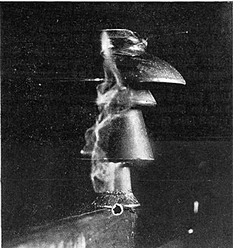
Fig. 13 shows the insulator used. The middle and lower shells were cemented together at the factory, and the top shell cemented on in the field. Fig. 14 shows an insulator under test at 75,000 volts with a shower of water corresponding to a precipitation of 3/4 in. per minute, the test covering 15 minutes. The standard test under normal conditions is at 100,000 volts.
| |||
| Fig. 14. - Insulator Under Test at 75,000 Volts. |
Nine feet below the large cross arm is a 46-in. cross arm which carries a No. 9 iron-wire telephone circuit. The telephone line is transposed every half mile and is said to give perfectly quiet service, although there is an induced voltage between either side and ground sufficient to light an incandescent lamp. For the use and convenience of the men patrolling the line, telephones are connected at intervals along the route as well as at the power house and receiving station in Ogden. They are placed in booths so insulated as to protect the user from danger of an accidental cross between high-tension and telephone wires in case of a breakdown.
| |||
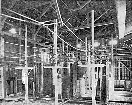
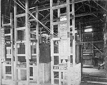
| Fig. 15. - Interior of Sub-Station, Showing High-Tension Bus-Bars, Transformers, Etc. |
| |||
| Fig. 16. - Interior of Sub-Station, Showing Lightning Arresters, Etc. |
The entire output of the Bear River plant of nearly 3,000 hp is sold by the Utah Sugar Company to the Utah Light & Railway Company, as already mentioned, and the latter company operates the station and transmission system. It has recently been decided to install a third unit at the power house of the same size and style as those now in operation.
The concrete work and power house were built under the direct superintendence of Mr. J. C. Wheelon, superintendent of the Utah Sugar Company's canal system. The entire plant and transmission system was designed and supervised by Hayward & Gray, consulting engineers of Salt Lake City. To Mr. O. H. Gray, successor to the firm of Hayward & Gray, appreciation is due for kindly supplying data and illustrations for this article.
A general idea of the extensive interconnected power transmission system in Utah may be obtained from the map, Fig. 17. This map shows the lines of the Utah Light & Railway Company, including the Bear River system, indicated by a heavy, full line, the circuits of the Telluride Power Transmission Company indicated in heavy broken lines and the system of the American Fork Canyon plant in crossed lines.
 |
| Fig. 17. - Map of Transmission Systems. |
The Utah Light & Railway Company operates the Bear River, Ogden and two Cottonwood water power plants and three steam stations in Salt Lake City. The Telluride company has a water power plant at Logan, 85 miles north of Salt Lake City, and another at Provo, 45 miles south. These two stations are connected by a duplicate pole line and at Salt Lake taps are taken off to a transmission sub-station of the Utah company situated close to a new station of the company in the western part of the city. At this station the power from the Telluride system and the company's northern lines is received and stepped down from 40,000 to 2,300 volts by means of water-cooled, oil-insulated transformers. This sub-station now has a capacity of 2,700 kw, but it is being rebuilt and enlarged and by fall will have a capacity of 6,000 kw and will receive the power from all the transmission lines of the company, including those from the Cottonwood stations, which now come into another sub-station at a lower voltage. The sub-station is equipped with lightning arresters, static interrupters, air-break switches and a complete set of indicating and recording instruments.
The steam station is called the Jordan station, as it is located on the bank of the Jordan River. It was erected as a temporary power house to carry the company through its peak loads until a large steam turbine central station now planned by the company can be erected. The equipment consists of six 250-hp Babcock & Wilcox boilers set in three batteries, and a 1,200-hp Hamilton Corliss engine, which drives by means of a large belt a 750-kw alternator. This plant is used for a few hours each night to help over the peak of the load.
It is interesting to note that these six water power and three steam stations are all operated in parallel through the low-tension side, and although some of the stations are nearly 150 miles apart the generators operate in perfect synchronism.
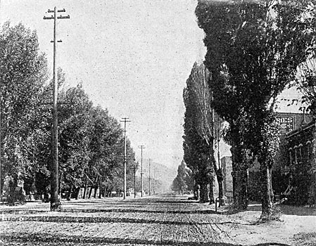
Fig. 18 is interesting as showing how a high-tension transmission line from the Cottonwood plants is brought through Fourth South Street, one of the principal streets of Salt Lake City, on 60-ft. poles. These poles are set in the center of the street, as are practically all poles in the city on account of the unusual width of the streets.
| |||
| Fig. 18. - High-Tension Line, Salt Lake City. |
An interesting transmission system in Utah is that from American Fork Canyon to Utah Lake and indicated on the map by crossed lines. This system is a striking illustration of the use of water power as an aid to irrigation. The power in this case is transmitted electrically to the head of Utah Lake, where it is used to drive four 100-hp pumps, which raise about 500 cu. ft. of water per second out of the lake into a system of five large canals. These canals irrigate the Salt Lake Valley. Power for the pumps was formerly supplied by the Jordan Narrows plant, but the American Fork plant has recently been enlarged and the transformers at the pumping plant have been rearranged for this purpose. The reconstruction work was done by Mr. Owen H. Gray.
