[Trade Journal]
Publication: Electrical World and Engineer
New York, NY, United States
vol. 44, no. 4, p. 129-132, col. 1-2
A Hydro-Electric Power Development on the Catawba River, Near Rock Hill, S. C.
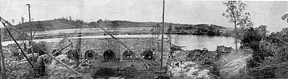
THERE has just been completed at India Hook Shoals, on the Catawba River, at a point about six and one-half miles from Rock Hill, S. C., what is probably the most complete and certainly one of the most interesting hydro-electric developments in the South. The plant was installed to supply electric power to cities and towns within a radius of some 18 miles. The drainage area for the hydraulic equipment is about 3,000 square miles, with annual precipitation of about 50 in. A minimum flow through rainfall for the four seasons of the year averages 2,100 cu. ft. per second. This flow, according to Government records, was about 1,500 cu. ft. per second, but subsequent weir measurements taken over the crest of the dam justify its being placed at the above figure.
An effective head of 22 ft. of water in the dam, guaranteed under the severest of conditions, and a flow of 3,619 cu. ft. per second, gives a gross output of 9,033 hp, or, at an efficiency of 66 per cent., 5,962 net hp. For nine months out of the year an amount of power equal to 7,611 hp is available for the day run of 12 hours and 1,000 net hp for the 12-hour night run, permitting the sale of secondary power for the nine months of 1,649 hp for the 12-hour day run. The entire length of the dam is 1,266 ft. and of the spillway 585 ft. The impounding structure of the plant consists of a masonry-core earth dam, the power house acting by virtue of its position as masonry dam and retaining wall for the forebay.
| |||
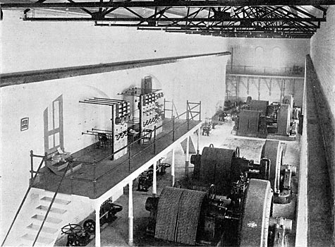
| Fig. 1. Switchboard and Machines of Present Installation. |
The power house, with its foundations of granite masonry, is honeycombed with arched openings for the housing of the various machines and for affording entrance and exit for the water. In this section there are eight bays. The bay nearest the spillway, the penstock of which serves both the large power unit and one exciter, is built to more ample dimensions than the others, which are identical in all respects. In each penstock is located a water wheel unit composed of three 54-in. special pattern Hercules turbines mounted on horizontal shafts and having a total capacity of about 2,100 hp. The efficiency is guaranteed at 80 per cent. from to full gate, under a 25-ft. head, each turbine using approximately 15,000 cu. ft. of water per minute at Ito revolutions. The present installation consists of but six units of water wheels, only the quarter-turns, bulkheads and draft tubes of the two additional units having been erected.
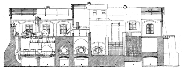 |
| Fig. 2. Longitudinal Section of Power Plant, Catawa River. |
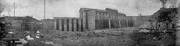
The power house is a brick structure with slate roof and supported by steel trusses, forming a light, airy housing for the generators and accessory machinery. The complement of electrical apparatus is of the newest and latest pattern. The generators are three-phase, 60-cycle, alternating-current machines, with capacity of 750 kw. They are of the revolving-field type and generate current at 11,500 volts, with speed of 300 r.p.m. The rated full-load current of each three-phase generator at a normal potential of 1,500 volts is 37 1/2 amp., there being required to excite the field at full non-inductive load a current of 75 amp. at 95 volts, the maximum exciting capacity under a 25 per cent. non-inductive overload being 15 kw. These machines are guaranteed to run for 24 hours continuously at 25 per cent. overload at 11,500 volts without excessive rise in temperature. Following are the guaranteed efficiencies, including friction: Full load, 94 per cent.; three-quarter load, 93 per cent.; one-half load, 90 1/2 per cent.
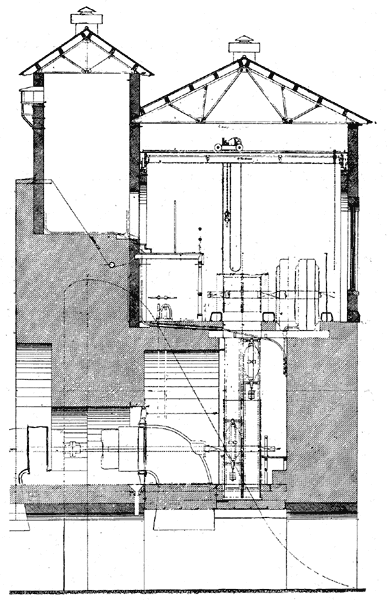 |
| Fig. 3. Cross-Section View of Power Plant. |
Four generators, with space for the installation of four additional machines, constitute the present equipment. Connection with the water wheels is effected by means of a rope drive of the American type, each machine having two sets with 16 wraps of 1 1/2-in. Manila rope. The driver has a pitched diameter of 13 ft. 10 in. and revolves in a water-tight pan to protect the ropes against any water finding its way into the pulley pits. The rope speed at the rated machine speed is about 4,780 ft. per minute, and tension is maintained by means of a weighted idler sliding on tracks and mounted at an angle with the drive. This idler also serves to feed the rope across the driving pulleys. The floor of the pulley pit is of concrete-steel construction. Leakage into it is removed through drains and by means of a 3-in. by 4-in. triplex power pump driven by belt from the water wheel shaft.
Two exciter units have been installed, with capacity sufficient to excite the complete installation of eight alternating-current generators, and to supply current for the lighting of the power house. The turbine installation consists of two 27-in. Hercules water wheels mounted on vertical shafts and capable of producing 170 hp under a working head of 25 ft. The same guarantee of 8o per cent. is made for these wheels as for the 54-in. wheels. Through a pair of mortice bevel gears a direct connection is formed between these wheels and a jack shaft, the latter being connected by link couplings to the shafts on which the generators are mounted. The wheels are controlled by cylinder gates operated from the floor of the power house. The electrical equipment of the exciter plant consists of two direct-current, 6-pole, 115-kw, compound-wound generators running at a speed of 450 r.p.m. and generating 125 volts. At a normal potential the rated full-load current of each of these exciters is 920 amp. and the machines are guaranteed to operate for one hour without movement of the brushes and without injurious sparking. Following are the guaranteed efficiencies without friction: Full load, 91 6/10 per cent.; three-quarter load, 90 1/2 per cent.; one-half load, 87 1/2 per cent.
| |||
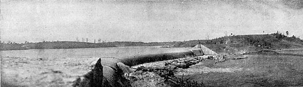
| Fig. 4. First Water Over Spillway. |
| |||
| Fig. 5. Setting of the Hydraulic Plant. |
| |||
| Fig. 6. Closed Gates and Power House, From Forebay. |
A flange coupling is used for connecting these two units, or either exciter may be operated from one of the wheels separately. The switchboard is mounted on a gallery overlooking the machines. By its use all generators may be operated in multiple on three feeder circuits and also the operation of any generator or set of generators separately on any feeder may be accomplished. The oil switches permit of the opening of the generator or feeder circuits under load. The switchboard is of the low-voltage type, all high-tension apparatus being out of reach of the attendants in a separate apartment off from the main room. The board consists for the present installation of ten panels on which are placed all necessary controlling and indicating devices. Of these panels four are for the generators, each containing one load ammeter, one field ammeter and one voltmeter, the instruments being of the horizontal, edgewise type. They contain also the operating handle for the oil switch and synchronizing device, this latter device consisting essentially of a voltmeter in connection with lamps and a receptacle on the panel, which makes such connections as to enable the use of the voltmeter either for synchronizing or for normal voltage reading.
Corresponding to this equipment there are mounted for each panel in the high-potential room a current transformer, two potential transformers, three single-pole, non-automatic, form K General Electric oil switches in soapstone compartments. These switches in these compartments are operated mechanically by means of rods and belt cranks from the switchboard. These devices are designed to rupture loads which under emergency conditions cannot exceed 6,000 kw at 13,000 volts for the three-phase circuit. For connecting the bus?bars there are also six single-pole, single-throw knife switches mounted on a platform above the compartments containing the transformers and switches. In each of the two exciter panels are contained one 1,200-amp. ammeter, a rheostat, a potential receptacle, two 800-amp., single-pole, single-throw lever switches with fuses on the rear of the panel. One of the panels also contains the device for the electric control of the governors. The exciter feeder panel contains one 175-volt voltmeter, two 50-amp. lever switches for station lights and six double-pole, single-throw field switches with discharge resistances. There are three alternating-current feeder panels, each containing three ammeters, a Thompson polyphase recording wattmeter, the operating handle for the automatic oil switches and the overload relay for the oil switches, the relay being operated by direct current from the exciters. For this equipment there are mounted in the high potential room two current transformers for wattmeter and ammeters, two potential transformers for the wattmeter, two current transformers for the oil switch and six single-pole knife switches for connecting the bus-bars. In addition two equalizer pedestals have been furnished for the exciters. The single-pole switches on generator and feeder panels are arranged to permit of connecting the generators and feeders to either or both sets of bus?bars. Lightning protection is provided by fitting each end of each wire with a 13,000-volt bank of lightning arresters having porcelain barriers. Tile pipe 4 in. in diameter carries all cables beneath the floor with the exception of the generator leads, which are carried on brackets along the side of the pulley pit.
Power is at present being furnished to three points: Rock Hill, S. C., 6 1/2 miles; Fort Mill, S. C., 3 1/2 miles, and Charlotte, N. C., 18 miles, and in the construction of the lines the two requirements of a successful long-distance transmission, continuity and regulation, as suggested by Mr. F. A. C. Perrine, in a paper read before the Boston Society of Arts, have been kept well in mind. The design of the generators provides for the regulation, as there is a guarantee on the machines that the inherent regulation will not exceed 6 per cent., and that at 90 per cent. power factor and 37 1/2 amp. at 11,500 volts, the regulation will be within 15 per cent.
| |||
| Fig. 7. Pole Top for 22,000 Volts. Fig. 8. Pole Top for 11,500 Volts. |
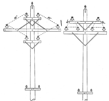
Two of the new type N Lombard governors are used to control the speed of the alternating-current generators, two generators being connected in parallel and controlled by one governor. These governors are driven by belt from the generator shaft, being connected by wire cable to the water wheel gate. The governor develops approximately 30,000 foot-pounds on the gate rigging. The hydraulic cylinder, unlike other types, is placed vertically instead of horizontally, effecting a great saving in space. They are electrically controlled from the switchboard. Continuity has been sought by building the entire plant to withstand the utmost strains which may be imposed upon it, while the transmission lines were designed with a view to the greatest permanence. The poles are of cypress, juniper and chestnut, 35 ft. long, 14-in. butts, 7-in. tops and are buried in the ground a distance of 5 1/2 ft. The ground ends have been liberally coated with coal tar. The cross arms are of long yellow leaf pine painted two coats, the pins being boiled carefully in paraffine. On the Rock Hill line for a distance of six miles, the poles are spaced 100 ft. apart and are to carry two circuits, each of three wires spaced in form of an equilateral triangle with 24-in. legs (Figs. 7 and 8). No. 1 and No. 2 Imperial porcelain insulators were used indiscriminately. These insulators are of the one-piece, triple-petticoat pattern. No. 1 is 6 in. in diameter and 4 in. high and stands a test of 45,000 volts. No. 2 is 5 in. in diameter, 3 7/8 in. high and stands a test of 40,000 volts. Being of a dark color they are not likely to attract the aim of small boys with rifles. They are mounted on 1 1/2-in. locust pins, 11 in. long and carry No. 0 hard-drawn bare copper wire tied with No. 10 wire. The transmission circuits will carry the finally contemplated 3,000-hp output with a line loss not exceeding 10 per cent. A barbed wire for lightning protection is carried on special brackets and supported on pony insulators along the top of the poles, being grounded wherever good ground could be obtained. A metallic circuit telephone line is maintained 15 ft. above the ground and at a distance of II ft. from the high-potential circuit. This circuit consists of No. 12 B. B. galvanized-iron wire transposed every third pole, and is giving satisfactory service. A weather-proof wire is used within the city limits.
The transformers are of the oil-cooled type, wound for 11,000 volts primary circuit and either 2,200 or 550 volts secondary circuit. At all points where consumers have tapped the line, or where transformers have been installed, danger of interruption has been minimized by the use of automatic oil switches with lightning arresters.
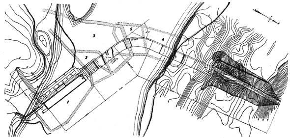 |
| Fig. 9. Topographical Plan of Property. |
On the line to Fort Mill and Charlotte, the river was crossed by means of two spans each 350 ft. in length, a timber crib loaded with stone having been built in the middle of the river, on which were erected a well-braced A-shaped tower carrying beams on which the two circuits were placed. The wires are here spaced 6 ft. apart. To the point where the line to Fort Mill separates from the line to Charlotte, 1 1/2 miles from the power house, the poles are placed 100 ft. apart and are to carry two circuits of No. 0 hard-drawn bare copper wire with a spacing of 4 ft. Thomas No. 6 T porcelain insulators are used. These are 6 3/4 in. in diameter and 5 1/2 in. high, withstanding a brine test of 70,000 volts. It is intended for the present to operate this line at 11,500 volts, but it is expected eventually to install power house transformers to step the pressure up to 22,000 volts.
From the junction with the Fort Mill line to Charlotte an aluminum cable of 208,000 circular mils is used upon poles spaced 150 ft. apart. Transposition of the wires of these circuits is effected by spiraling every 2 1/2 miles, two complete revolutions being made. It is designed to carry 3,000 hp with a loss not to exceed 10 per cent. over this line. The lightning protecting and telephone equipment is similar to the one on the Rock Hill line. Over the Fort Mill branch on poles spaced 125 ft. apart, the current is conducted on No. 2 copper wire.
At Charlotte it is proposed to erect a sub-station. The step-down transformers there are wound for 20,000 and 11,000 volts primary and 2,200 and 550 volts secondary circuit. An auxiliary steam plant will probably have to be erected at this point, but mills and other large consumers will be served from the high-potential circuit.
To Mr. Emil Knichling, of New York, is due the design of the hydraulic portion of the development, while the engineering features of the whole equipment have been under the direction of W. S. Lee, Jr., of Rock Hill, S. C., as vice-president and chief engineer of the Catawba Power Company. The plant was conceived and financed by Dr. W. Gill Wylie, of New York, and cost over $1,000,000.
