[Trade Journal]
Publication: Electrical Age
New York, NY, United States
vol. 33, no. 2, p. 135-144, col. 1-3
A 100-Mile Electric Transmission Line
From Spokane, Washington, to the Coeur DAlene Mine District
By ROBERT HOWES
Mr. Howes paper was originally presented at the last annual meeting of the National Electric Light Association, but for its use here the author has added later available data and also the several photo-graphic illustrations. The Editor.
IN the following it is not the author's purpose to indulge in long explanations, descriptions or theories, but rather to give a brief description of the essential features of the plant and the transmission line, of the results obtained, and the difficulties encountered. The plant considered is that of the Washington Water Power Company, of Spokane, Wash. The power house is located at the foot of the lower falls of the Spokane River, in the very center of the city of Spokane. The theoretical head on the water-wheels is about 71 feet.
| |||
| The Lower Falls and the Power House at Spokane, Washington. the Available Head is About 70 Feet, Making 4000 H. P. Available for Transmission to the Coeur D'Alene Mine District. the Power is Employed Principally for Operating Mine Hoists and Air Compresssors, Though There Are Other Minor Uses for It, As Told in the Article. |
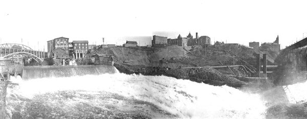
That portion of the plant which furnishes the power for the transmission line is composed of two Y-connected, 4000-volt, 2250-K. W., 60-cycle revolving field alternators, running at 300 revolutions per minute, each direct-driven from a pair of 40-1/2-inch special turbines, made by the Stillwell Bierce & Smith Vaile Company, and designed to develop 4000 H. P. under 68 feet of effective head. The water is supplied to each unit through a steel flume 10 feet in diameter and 500 feet long.
The wheels are governed by Lombard governors, with compensating action modified to meet the demands occasioned by the kinetic energy of the water moving in the long flumes. These governors can be relied upon to keep the speed from rising or falling over 3 per cent. from the normal with instantaneous changes of 600 K. W. at any position of the gates, and they will care for small changes of load to within one-third of 1 per cent. of normal speed.
The diagram on page 139 gives the important electrical connections. All instruments have been omitted to avoid confusion of lines; but a complete set is installed. Each generator is supplied with voltmeters, ampere-meters and wattmeters in each leg, and the leads to the step-up transformers are also provided with ampere-meters and a power factor indicator. By running one of the generators alone on the transmission line a complete set of instruments, voltmeters, watt meters, ampere-meters and a power factor indicator is available for that unit. All the electrical apparatus is of the General Electric Company's make, the indicating instrument being of the horizontal edgewise type.
The principal exciter is driven from a separate wheel, which is supplied with water from either of the two flumes. An induction motor, not yet in operation is to he connected to the end of the exciter shaft, opposite the water-wheel, and driven from the transmission leads inside the oil circuit-breakers. It will serve the double purpose of governor and insurance against lack of power for the exciter if the chute-case of the waterwheel becomes partially choked up. An indicating wattmeter on the induction motor will indicate the choking of the water-wheel by showing that the motor is taking more load. The exciter will then he started and the choked wheel cleaned out.
The plant is designed to furnish three-phase current at 4000 volts for local power, and for step-up transformation to the end of the line, and 2300-volt, single-phase current for local lighting service in Spokane. Any lighting feeder can he thrown on any of the three legs of the Y-connected generator by means of the oil switches, and the load on the generators kept balanced. Hand-operated voltage regulators are installed on the neutral or grounded side of each lighting feeder the voltage being regulated with the aid of a voltmeter compensated for the line loss.
| |||
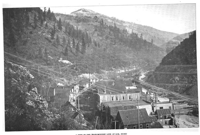
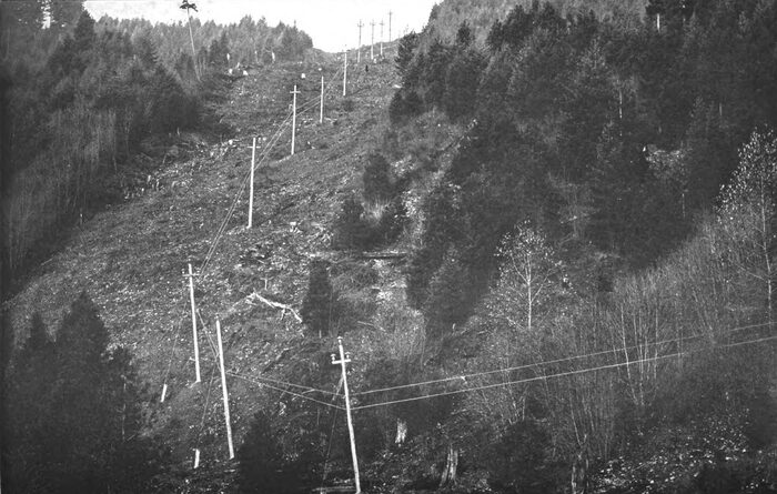
| A View of the Transmission Line at Gim, Idaho |
The generator transmission line and main city switches are motor-controlled. Those on the transmission line and city have automatic overload tripping devices. The city feeders have automatic oil circuit-breaker switches, hand-operated.
The step-up transformers are 750 K. W. each, and are of the water-cooled type. They are connected in delta on the 4000-volt side, and in Y on the high-tension side, the neutral connection being grounded at the power house. The high-tension winding is for 34,700 volts, taps being brought out for 26,000 volts also, thus giving a choice of 60,000 or 45,000 volts line pressure. With the arrangement of connection, it will be understood, each transformer is wound for 58 per cent. of the voltage of the circuit. Two spate transformers are installed, and the switching arrangement is such that one of the spare ones can be cut in to replace any of the three in use without shutting down. The second spare one can be connected on any phase by shutting down about one minute.
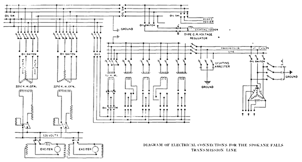 |
| Diagram of Electrical Connections for the Spokane Falls Transmission Line |
Three banks of lightning arresters are installed on the lineone at Spokane, one at the end of the line and one about 20 miles from the end of the line.
The main line is 98 miles long at the farthest sub-station and has three short branches at present. Low-tension current is transmitted about 2 miles up the canon, making the total transmission just 100 miles.
On leaving the power house, the line goes through the city streets for 3-1/2 miles, the poles used being from 40 to 85 feet long, in order to get above everything that might be interfered with. Whenever it crosses other lines, grounded wires are strung over the latter several feet below the transmission line.
| |||
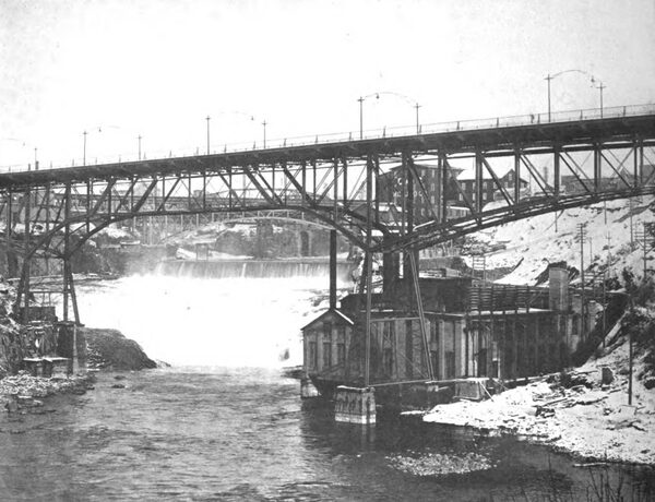
| A View of the Lower Falls and Power House at Spokane |
| |||
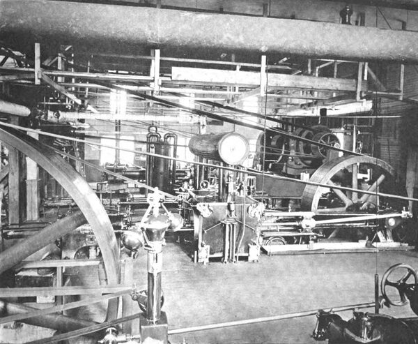
| Two of the 300 - H. P. Induction Motors Which Have Displaced Steam Engines |
Leaving the city, the line follows a country road for about 24.5 miles, till it reaches the Coeur d'Alene Indian reservation. Across this, a distance of 24.8 miles, almost wholly in heavy timber, a private right of way was obtained and cleared of all trees and brush. All trees outside the right of way, and liable in falling to reach the line, were also felled. At one point in this portion the line crosses the St. Joseph River at the point at which the river empties into the Coeur d'Alene Lake. The river runs close to a bluff on the west, while on the east side there is a marsh and the neck of an inlet.
At high water several feet of water stands from bluff to bluff. To span this would require 3300 feet, so setting the poles on a cluster of five piles was resorted to. The center one was driven about 6 feet lower than the others, and a socket was formed in which the pole was firmly clamped with heavy iron bands. By this means the longest span across the river channel was reduced to 474 feet, the wires being far above the smokestacks of the steamers that navigate the river. Number 0 B. & S. hard-drawn copper wire was used here for further security against a wire breaking. A row of single piles with a plank walk was placed across the marsh under the line, for patrolling purposes. Thus far this construction has proved most satisfactory.
| |||
| A Sharp Turn in the Transmission Line |
Leaving the reservation, the line follows up the valley of the Coeur d'Alene River and its south fork to the mining region. It is largely on Private right of way, but follows country roads in part, and goes through swamps and meadows sometimes several feet under watertimber-covered mountains, steep rocky mountain sides and around rocky cliffs. As far as possible, it was considered best to avoid proximity to towns, railroad tracks and the like where the youth with a 22-calibre rifle likes to walk and practice shooting, for the insulators offer a tempting target to those of a mischievous nature.
The poles of the present line are set 35 feet from the north or westerly side of the 100-foot right of way, leaving room for a duplicate line on the other side.
| |||
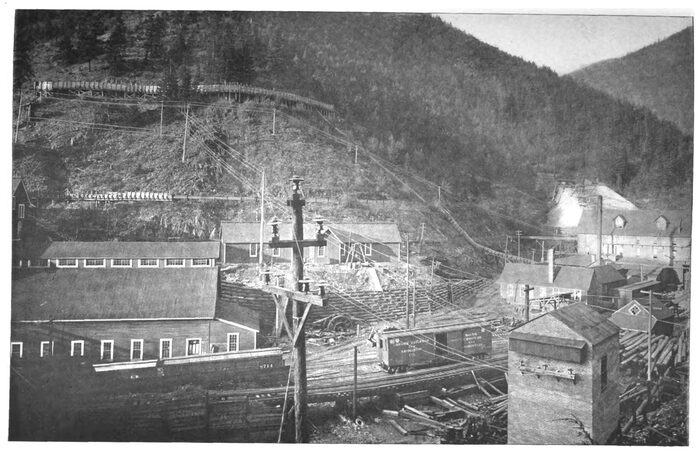
| The End of the Transmission Line at the Burke Step-Down Transformer Station, Idaho |
The standard pole is 35 feet long, of winter-cut cedar 12 inches in diameter at the ground line and 8 inches at the top. They are set 6 feet in the ground. Special lengths are used in hollows, at the bottom of ravines and the like, to avoid making too great a change in the slope of the wires on any one insulator, and also at railroad crossings and in villages.
The wires are of No. 2 B. & S. medium, hard-drawn copper, and are placed to form an equilateral triangle 42 inches on a side. The upper insulator is set on the top of the pole, the others at both ends of the cross-arm. A complete set of three partial transpositions is made in each section where the condition varies in parallel-telegraph, telephone and other lines: otherwise it is made every mile.
A private telephone line is run on the side of the poles below the power line and is transposed every few spans. The insulators used are of the double-petticoat type, 13-inch size, and are mounted on a metal pin. This pin is described by Mr. D. L. Huntington in the "Transactions of the American Institute of Electrical Engineers" for April, 1903, page 453, and has given entire satisfaction to date.
The sub-station buildings are of brick. The high-tension wires, entering near the top, go directly to knife-disconnecting switches, set on a gallery, and thence to the transformers on the ground floor. One transformer of the three-phase type is used. The secondary wires pass from the trans-former to a switchboard carrying oil circuit-breakers, recording wattmeters and indicating instruments, and thence to the customers' circuits. The half-voltage taps shown on the diagram are only for starting purposes for synchronous motors. There are eight of these sub-stations, six of which have been in continuous use since starting. Besides the foregoing, there is a sub-station recently built about 11 miles from Spokane, where power is taken from the transmission line and the voltage stepped down to 23,000 to supply the lines of an interurban railway 33 miles long. The railway company uses the power through rotaries to supply the trolley with 600-volt direct-current.
Several miles of long-distance telephone line parallels the transmission line at a distance of about 40 feet, and one of the telephone company's engineers was much worried, fearing trouble with the operation of these lines. Three days after the transmission was in operation, he asked when the current would be turned on as he wished to notice how much the change was. Upon learning that the current was on, he admitted he could not detect it in the operation of the tele-phones. There is very little sound on the private telephone line from induction, unless one of the telephone wires becomes grounded, when it is almost impossible to understand a person talking over the telephone.
A rather peculiar loss of from 1 to 6 feet of head in the draft tubes is encountered at the ordinary height of the river. The center of the wheel-shaft is then about 18 feet above tail-water. Not far above the intake to the power house the river divides into several channels and falls about 60 feet over numerous small dams and cascades composing the "upper falls reaching this level a few hundred feet above the intake. There being no quiet water whatever, considerable quantities of air seem to be taken into the flumes with the water, no doubt held there under pressure as the water flows down the flumes, to be instantly released upon passing through the wheels into the partial vacuum in the draft tubes. This, no doubt, explains a part of the loss of head.
Another peculiar phenomenon is noticed every time one of the 4000 H. P. wheels is started. Of it the writer has found no satisfactory explanation and would be glad to hear one. The following characteristic observations were recorded by him:The gauge pressure at the center of the wheel-shaft being noted as 24 pounds and the vacuum in draft tubes being zero, the gate of the wheel was opened slowly. Full speed was reached in about one minute, the gate being opened 9 per cent. The vacuum was noted as rising rapidly. The speed remained steady for two or three minutes and the vacuum increased to 10 inches of mercury; suddenly the wheel slowed down 20 per cent., the vacuum continuing to rise to about 13 inches of mercury, where it remained practically stationary. The wheel continued to run at steady speed --20 per cent. lowuntil the gate was further opened it requiring 16 per cent. gate opening to bring the wheel back to speed. The pressure gauge showed a loss not exceeding one-tenth of a pound, while the vacuum remained about the same.
The power house being ready before the line was completed. 77 miles of line were first tested. All switches were closed and the generators started slowly from rest. The speed was gradually increased, the connections haying been made for 60,000 volts pressure. The pressure was brought up to 42,000 volts and then cut down slowly to zero without any indications of trouble.
| |||
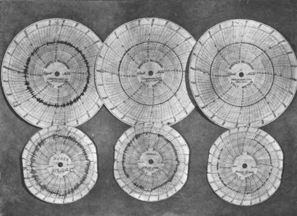
| A Study in Voltage Regulation |
Next morning the machine was started again in the same manner, the voltage being raised to about 68,000 volts for a short time, and then lowered to about 58,000 or 60,000 volts, and held there all day while the entire line was patrolled and was found to be in good condition. Along the line a discharge could he heard at a large percentage of the insulators. With 58,000 volts on the line, the amperes shown on the generator were 230 in each leg, white the wattmeter indicated 25 kilowatts per leg. This would show the charging current to be approximately 15 amperes, while, after the step-up transformer loss was deducted, the remaining energy lost in the line would not he over 10 K. W. per wire, or a total of less than 30 K. W.
In this test only one set of lightning arresters was connected, that being at Spokane each division of the set was composed of 24 General Electric 2000-volt, double-pole arresters connected in series, thus forming 96 spark-gaps from each wire to the ground. A steady stream of sparks could be noticed through the first few air-gaps. These became less frequent as the number of gaps crossed became greater, and before reaching half-way down the arresters the sparks were no longer visible.
The leading current exerted such an exciting effect on the generator that the exciter voltage had to be reduced to 85 volts and all the generator fields resistance cut in, giving an exciting current of about 50 amperes, whereas, with the generator half-loaded with non-inductive load, the exciter was run at 115 volts with the generator rheostat handle in about central position.
After this test the line was shut down for four days, the transformers were connected for 45,000 volts line pressure, and the first sub-station, 79 miles from Spokane, was cut in. The voltage was brought up to 43,000 volts, and simultaneous volt readings were taken by means of telephone. the voltage being very steady. The voltage indicated at the sub-station was a little over 44,000 The voltmeters were new, but were not compared; however, the error ought not to have been 2 per cent. The amperemeters in Spokane on the 4000-volt side of the transformers indicated 120 amperes, giving about 10.5 amperes for charging current at this voltage, there haying been 2 more miles of line and an unloaded transformer and bank of lightning arresters at the sub-station cut in since the test at 58,000 volts.
During the first test the neutral wire was not grounded at the power house. and the floating around of the neutral point was plainly noticed on the lightning arresters, the sets connected to the three wires showing considerable difference, sometimes one being most active and then another. Grounding the neutral wire stopped the greater part of this effect, although a slight varying difference still seemed to exist.
As induction motors were started, the amperes supplied to the step-up transformers decreased until a minimum reading of about 95 amperes was reached. The kilowatts were not observed, owing to the generator furnishing current to the city as well at this time, and the proportion of the total supplied to the city and the line could not be accurately obtained. After this time, adding more load increased the current; accordingly the minimum current is about 8 1-3 amperes for 79 miles of the line at 43,000 volts.
The work was rapidly pushed to completion and the sub-stations were put in operation. each sub-station being put into service as soon as the line reached it. The power was cut off only long enough to make connections to each piece of new line. Accordingly there was no opportunity to test the charging current and the kilowatts of the complete line, for one could never be sure that the whole of the load was off at the various sub-stations. From two of these current is supplied for lighting purposes, the towns of Wardner and Kellogg being lighted from one.
At the time of writing, unity power factor is usually reached with a load of 1450 K. W. The current in the line is then about 18.5 amperes per wire. Four 300-H. P. induction motors, one 240-H. P. synchronous motor and several induction motors of smaller sizes are in operation on the line. One of the 300-H. P. induction motors is supplied from the sub-station at the end of the line, and is direct-connected to a hoist which is in almost constant use. During the first two months the motor had to be run entirely unbalanced, the effect of this hoist upon the regulation of the line being at first very serious.
The motor is a three-phase General Electric built for 514 revolutions per minute, 2080 volts and 60 cycles. When the load on the line was light and this motor was started, it threw a heavy inductive current on the line increasing the power factor instantly leaving the generator much under-excited, and causing the voltage to drop. To this had to be added a drop of about 1 or 1-1/2 per cent., owing to drop in speed. The speed was about recovered when the load came off again, restoring the power factor and excitation to the generator, while the speed rose about as much as it fell on starting the motor, causing the voltage to go slightly above normal.
Ordinarily, the voltage at Spokane fell about 10 or 12 per cent. and rose 2 per cent. from normal, while extreme cases were nearly twice as bad. The voltage at the end of the line varied in general about 1.6 times as much as it did at the power house. This action continuing even two or three minutes, needless to say, made the power unsatisfactory for lighting purposes, while the speed variation of the induction motors was enough to bring forth severe complaint where they were used to run milling machinery requiring a very constant speed.
Even the 240-H. P. synchronous motor, mentioned in the foregoing, judging from the attendant's account, started to fall out of step, slipped over a few poles, and again got in step, though causing much anxiety. After a day or two of this, a man was put in constant attendance on the generator rheostat, and the writer went to the end of the line to study conditions and see what could be done. He found that the motor as then handled took about 275 kilovolt amperes for the first point on the controller. The operator then moved the handle rapidly, bringing the kilovolt amperes up to 400 or 450, made the run and shut off quickly. The time of raising a car from the 300-foot level was twenty-five seconds, and from the 600-foot level was forty-five seconds. It was noted by comparing recording voltmeter charts that die attendant at the switchboard in Spokane could do little to keep the voltage from falling, but could bring it back very quickly.
When the motor was cut out the voltage rose nearly as much as it dropped before. However, the general effect was much improved. It was found that the controlling rheostat of the motor was too small to stand regulating the speed of the motor for any considerable time, so, as a temporary makeshift, a resistance was made of iron wire and inserted in the circuit between the starting box and the rotor. This had the effect of cutting clown the kilovolt amperes taken at the first point to about 175, and the operator could then move the controller handle more slowly.
The first instantaneous drop in voltage was much reduced, and the attendant at the power house had a chance to hold the voltage nearer normal.
With this condition the voltage usually fell at the power house about 6 or 7 per cent., and rose nearly as much above normal. While this gave rather poor lighting service, it did not seriously interfere with the motors. This arrangement, however, has the bad feature of running the motor at a slower speed and so doing only the work of a small motor. This is not serious while operating from shallow shafts, but would be unsatisfactory for deeper workings in the future.
The writer accordingly recommends for such requirements a rheostat large enough not to overheat when running with any part of it in use, the first point giving a current nearly as small as that taken by the rotor with the rotor open-circuited. The second point would increase the current about 30 per cent., the next 30 more, the remaining ones more gradual changes. The motor would not start until the third, or if heavily loaded, perhaps the fifth, point. The controller handle also ought to have a time relay device, making it necessary to consume about three seconds between the first and second points, two between the second and third, and one for the next, and also a smaller time limit for cutting out these points.
An emergency switch ought to be provided so that the operator could cut off the current instantly. if necessary. This would enable the power house to care for the small changes and keep the voltage near its standard there, the line loss being the principal thing left to contend with.
A large water rheostat was installed at Spokane and used in connection with the transmission line, and was found to be of use on light loads ; but when he power factor reached too per cent. it did little good and could be cut out.
The voltage regulator for the power house and a larger controlling resistance for the hoist motor have been installed since this paper was first written. The illustration of charts on this page shows the effect upon voltage regulation. Those in the upper row were taken at the power house, while those below are the corresponding charts taken at the end of the line. There is an hour's difference in time, that at the end of the line being one hour before that at Spokane. The charts are changed at different hours.
Those on the left are average charts after the temporary resistance had been installed at the hoist mentioned in the foregoing, and with constant attendance at the generator rheostat. The author regrets that he has no representative charts of the condition before making the temporary change. The charts in the center show the voltage under the same conditions after installing the voltage regulator. Those on the right show what was obtained after the new controlling resistance was installed on the motor.
A suggestion was made to install a large synchronous motor at the end of the line, with no load except its own exciter, and install one of these regulators to operate on the field of this motor. If the line voltage drop, the regulator should strengthen the motor held and throw a leading current on the line. If the voltage rose, the field should be weakened to throw a lagging current on the line. The objection to using a motor installed for other purposes is that the motor would often be shut down, and would be largely out of the power company's control.
It may be of interest to note that while the line has been in continuous operation for over seven months, the circuit-breaker has been tripped only eight times. except when arrangement for a short shut down has been made with all the parties interested Of these eight trippings, two were caused by accidental short-circuits on the line, made by the company's workmen; four were short-circuits on the secondaries of customers, and were severe enough to throw out the secondary breaker, the sub-station breaker and the power house breaker all at once; the other two were from unknown causes. The total time the power has been off because of these troubles is thirty-two minutes.
