[Trade Journal]
Publication: Electrical Age
New York, NY, United States
vol. 33, no. 3, p. 177-185, col. 1-3
Construction and Insulation of High-Tension Transmission Lines
By M. H. GERRY, Jr., General Manager of the Missouri River Power Co., Helena, Mont.
A Paper Read at the International Electrical Congress at St. Louis, September 12-17
THERE are in America at the present time about ten systems operating regularly at tensions of not less than 40,000 volts and transmitting energy from 60 to 150 miles. Two of these transmissions employ pressures of between 50,000 and 60,000 volts. All of these systems have been constructed within the past decade and, while they represent commercial enterprises of considerable magnitude, their chief interest lies in the possibilities which they suggest for future developments. The following paper briefly discusses the problems connected with the construction and insulation of transmission lines, without touching upon the generation of the high-tension current or its manipulation within the generating or receiving stations. The examples of methods of construction and details of design described are drawn entirely from American practice. The term "high tension" where used refers to electrical pressures such as mentioned above.
GENERAL DESIGN.
In the construction of high-tension transmission lines wooden poles have been used for supporting the conductors almost exclusively; but there is a tendency at the present time to substitute metal, and the more permanent material will doubtless be employed in the future wherever the undertakings are of sufficient magnitude to justify the larger investment. Excellent results have been obtained, however, from the lines now in operation, and the current practice may be followed with a certainty of satisfactory performance and reasonable cost of construction.
Many of the transmission systems are located in a mountainous country difficult of access, and the obstacles overcome have been numerous and varied. 'Whenever the nature of the service is important, a private right of way has usually been secured and two lines of poles erected.
Cedar poles are used in the majority of cases, but redwood, pine and other woods are also employed to some extent. Cedar has an advantage over the other common woods in that it will last longer in moist ground. The pole tops and butts are frequently treated with coal-tar or some preservative compound, but this practice is not universal. Poles for important transmission lines are usually selected with care and are heavier and of better timber than those for other classes of service. They are of lengths varying from 35 to 75 feet, with diameters at the tops of from 8 to 14 inches.
For conductors, both copper and aluminium are employed. Copper is used as a solid wire in the smaller sizes, and as a stranded cable when of considerable dimensions. Aluminium is now always employed as a stranded cable. With either metal the flexibility, elasticity and strength are improved when in the form of a cable. Copper may be obtained either soft or hard-drawn. The hard-drawn material has greater tensile strength than the soft or annealed, and for that rea-son is often preferred.
Copper conductors should not, however, be subjected to a greater strain in service than the limit of safety of the soft metal, for the reason that the hard-drawn material may be annealed locally, either during erection while making connections or while in service by the heating of a joint, or from a short circuit. Aluminium is much the lighter metal for equal conductivity, and this is of some advantage during construction. On account of the greater coefficient of expansion of aluminium more attention is necessary to temperature conditions at the time of erection, so as to limit the sag and resulting stress developed. Equally good results may be obtained, however, with either metal if properly installed.
The cross-arms in use on most transmission lines are either of fir, or of long-leaf, yellow pine. Selected timber is usually employed, and the cross-arms are of special dimensions for this service. In the future, structural steel will probably be used to a considerable extent for this purpose.
The pins supporting the insulators are made either of wood or of metal. Of the various kinds of wood, locust, oak and eucalyptus are mostly in use. Mountain locust from old trees is perhaps the most satisfactory, but it is difficult to obtain. Oak if well-seasoned, gives good results, and eucalyptus has some excellent qualities. Metal pins are made of steel or cast-iron. Steel pins are the more reliable, as they are not subject to flaws and do not fail from internal strains. For fastening together the poles, cross-arms, braces and pins, through bolts are now usually employed.
 |
| Fig. 1. -- Pole - Top for High - Tension Line of the Washington Water Power Company |
 |
| Fig. 2. -- Composite Pin for High - Tension Insulator for the Washington Water Power Company. |
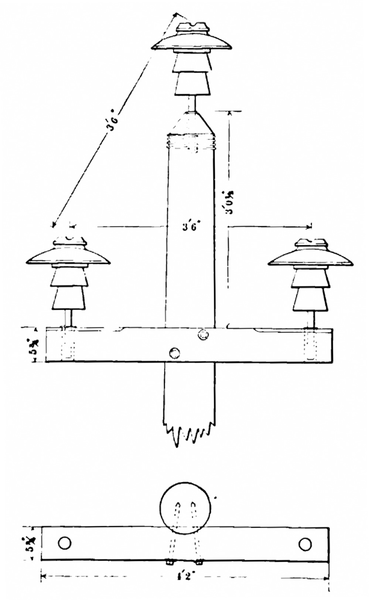
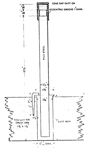
Various details of construction from current practice are shown in the examples following:The standard pole construction of the Washington Water Power Company, of Spokane, Wash., is shown in Fig. 1. This company has recently completed an important transmission from Spokane to the Coeur d'Alene mine district, 100 miles in length, and designed for an ultimate tension of 60,000 volts, although now operating at 40,000 volts. The conductors are of No. 2, B. & S. gauge, medium hard-drawn, solid, copper wire. The insulators are of porcelain and are brown glazed. The distinctive features of this construction are the short distance of 42 inches between the conductors and the special form of steel pin employed to support the insulators. This pin is illustrated in Fig. 2 and is worthy of notice. It was designed by D. L. Huntington, general manager of the company.
 |
| Fig. 3. -- Pole-Top for the Shawinigan Transmission Line |
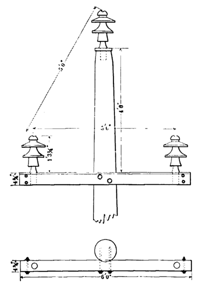
Another interesting illustration from current practice is shown in Fig. 3, which is the pole top used by the Shawinigan Water & Power Company, on the St. Maurice River, Canada, for their Montreal transmission. The length of this line is about 84 miles, and it is now operating at 53,000 volts. The conductors are aluminium cable, each made up of seven strands of No. 7 wire. The insulators are of porcelain, made in three parts, and arc supported on wooden pins. They were especially designed for this installation by Ralph D. Mershon, the consulting engineer of the company.
 |
| Fig. 4. Pole-Top for the Madison River Transmission |
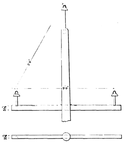
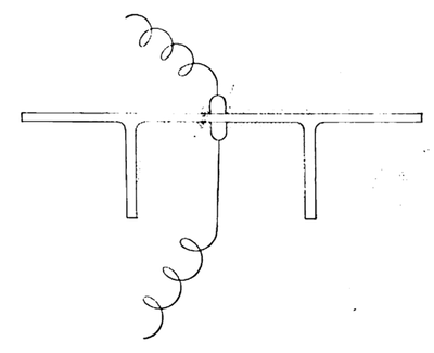
A novel construction is shown in Fig. 4. This is the arrangement used by the Madison River transmission running into Butte, Mont. It is remarkable for the entire absence of metal, with the exception of the conductors. The cross-arm extends through the pole and is held in place by wooden wedges and a wooden pin. This line is about 70 miles in length and operates at 40,000 volts. It employs glass insulators supported by wooden pins, and the conductors are of aluminium cable. It was built under the direction of P. N. Nunn.
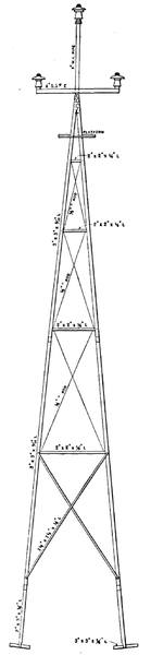 |
| Fig. 5. -- Four-Post Line Tower of the Guanajuato Power & Electric Company, Mexico |
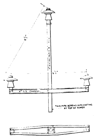 |
| Fig. 6. -- Pole-Top for the Guanajuato Power and Electric Company's Line |
A transmission which employs steel towers for supporting the conductors has just been completed in Mexico by the Guanajuato Power & Electric Company. Fig. 5 shows a standard tower and Fig. 6 the arrangement of cross-arms, pins and insulators. The towers are of a type used for supporting windmills and are of very light construction, the various parts being fastened together by means of special-bolted fittings. All the metal parts are galvanized. The towers are supported by anchors held in place by concrete foundations located at the four corners of the structure. A length of extra heavy 3-inch pipe, supporting the cross-arm and the top pin, extends above the tower. The pins art of cast-iron and the insulators of porcelain. The spans are said to average 500 feet, while the sag of the conductors is about 18 feet. The conductors are of hard-drawn copper cable. This transmission is intended ultimately to operate at 60,000 volts.
| |||
| Fig. 7. -- the Country Through Which the Missouri River Power Company's Line Pass |
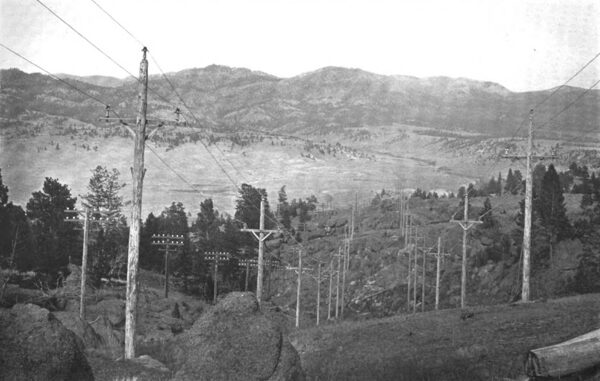
As a further illustration of current practice, the high-tension lines of the Missouri River Power Company, of Helena, Mont., built under the direction of the writer, are here briefly described. This transmission has been in service for over three years, operating at 57,000 volts and delivering at a distance of over 65 miles in satisfactory manner. The country through which it passes is very rough, as is shown in Fig. 7.
| |||
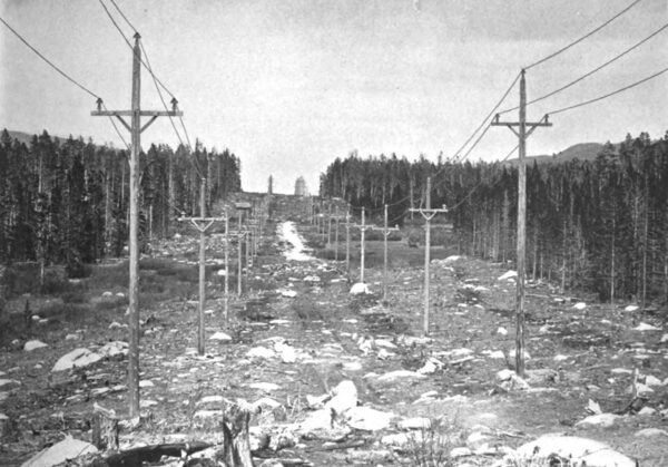
| Fig. 8.Along the Lines of the Missouri River Power Company. Private Right of Way, 200 Feet Wide, From Which All Timber Was Removed |
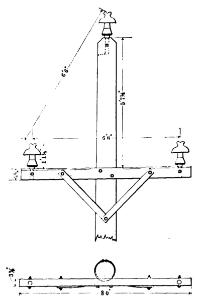 |
| Fig. 9. -- Pole-Top for the Missouri River Power Company's Line |
The lines leave the generating station at an elevation of about 3700 feet, and pass over three distinct summits, including the Continental Divide, at which point they reach an elevation of 7,300 feet above sea level. There are two parallel lines extending from the generating station on the Missouri River at Canon Ferry, Mont., to the Butte sub-station. These are located mainly on a private right of way 200 feet in width from which all timber was removed, as shown in in Fig. 8. Each of the lines carries three copper cables arranged in a triangular position, 78 inches apart. The cables are composed of seven strands and have an area of 106,000 circular mils. Fig. 9 is a drawing of the upper part of a standard pole. Fig. 10 is a section of the insulator, sleeve, pin and pole-top.
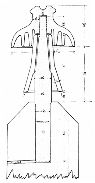 |
| Fig. 10. -- Section of the Missouri River Power Company's Insulator, Sleeve, Pin and Pole-Top |
The poles are of Idaho cedar, the cross-arms of Oregon fir, the braces and pins of white oak, and the insulators and sleeves of glass. The cross-arms, braces and pins are held in place by through bolts. The pins in the top of the poles are of larger size and of greater length than those in the cross-arms, to provide for the greater strains there present. The pins were prepared by being first dried and then treated in paraffine, until all moisture was removed, and were then tested to 60,000 volts. The glass sleeves are not fastened to the insulators and merely rest on a shoulder of the pins, as shown in Fig. 10.
The circuits are transposed five times, making two complete turns between the generating station and the sub-station. The switching arrangements are such that the circuits may be operated either singly or in multiple. A telephone circuit is located on one of the lines and gives good results in service. The poles are from 35 to 75 feet in length, and the pole-tops are from 9 to 12 inches in diameter. The poles are set from 6 to 8 feet in the ground, according to height, and the standard spacing is 110 feet, with a maximum spacing of 150 feet when required by the nature of the ground.
The constructions just described were selected as typical examples of what has been accomplished in the building of high-tension transmissions. Several of the lines mentioned have been in regular operation for periods varying from one to three years, and are in no sense experiments, but rather represent successful commercial undertakings. Other interesting and well-known systems might have been described had the limits of this paper permitted a further expansion of the subject.
LINE INSULATION
The design of insulation for high pressure ought to involve a consideration of all the effects of electrical tension on the dielectric in the vicinity of the conductors. In the case of a line insulator, air is always a dielectric in combination with glass, porcelain, wood or other materials. Wherever there is a difference of electrical potential, there exists in the surrounding media a state of strain called an electrostatic field. This state of strain is the result of electrical stress applied to the insulating material.
Dielectrics possess a sort of atomic elasticity, and electrical tensions produce a displacement in the molecular structure which, if carried beyond a certain limit, result in disruptive breakdown of the material. Before a difference of potential can exist current must flow into the dielectric, thus producing a state of strain equal to the electrical stress applied. If the material be not strained beyond its limit of molecular elasticity, current will flow from the material whenever the tension is removed or reduced and a path provided.
All dielectrics possess the quality of receiving strain before rupture, but not to the same degree. Solids and liquids generally possess it in a higher degree than gases. Whenever the limit of strain of a particular material is exceeded it fails structurally, resulting, with a solid, in a mechanical rupture, and, with a gas, in a change of molecular state which reduces its electrical resistance and renders it semi-conducting. It frequently happens, when several dielectric materials are subjected to the same electro-static field, that one or more of the materials will be strained beyond the limit and will fail, although the others may withstand the electrical strain. Air adjacent to powerful dielectrics frequently fails in this manner, thus giving rise to the common brush discharge.
The structural failure of air, from an engineering standpoint, has been studied by a number of investigators, including C. P. Steinmetz and Prof. Harris J. Ryan. It is well known that air at ordinary pressures and temperatures has a much lower dielectric strength than the common, solid, insulating materials. Air in thin films adjacent to solid bodies has greater strength than in bulk, but is still inferior to such substances as glass, porcelain, mica, treated paper, and the like. The dielectric strength of air is affected by the physical condition and varies directly as the pressure and inversely as the absolute temperature. Under uniform conditions all dielectrics rupture at definite, applied tensions. Prof. Ryan has shown that there exists also for each dielectric material a certain strength of electrostatic field which will cause rupture. When several materials in series form the dielectric, the one rupturing at the lowest value of electro-static field will fail first, although individually it may possess superior qualities.
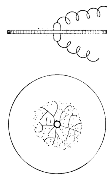 |
| Fig. 11 |
Line insulators are usually made of glass or porcelain, fashioned into a variety of shapes, all approximating certain elementary forms. Consider that alternating electrical tension is applied to a solid insulating disc, as shown in Fig. 11. If the pressure be low, only charging current will flow, but, if the tension be increased sufficiently, the air under and about the electrodes will be ruptured, producing brush discharge. This results in the formation around the electrodes of a zone of ionized air of comparatively low resistance. This enveloping zone of conducting air has the effect of increasing the size of the electrodes and, thus, the area to which the full tension is applied.
If the tension be further increased, the zone of ionized air continues to spread over the surface of the disc, thereby increasing its capacity and the resulting charging current. Streamers will now form on the surface of the plate and afford a path of still lower resistance whereby the current for charging the dielectric and ionizing the air is conducted to the outer portions of the ruptured zone.
When the surfaces of the solid dielectric are parallel, as in this case, the streamers and ruptured air zone, when once started, would apparently continue to spread indefinitely, were it not for the cooling effect of the adjacent material, the appreciable resistance of the path through the ionized air and the time element introduced by the alternating pressure. Under the conditions as shown in Fig. 11, the streamers may unite over the edge of the plate, thus forming a short circuit, the distance traveled being several times as great as the breakdown distance through air for the same pressure. This result is not due to surface leakage, as frequently assumed, but is a phenomenon of electro-static capacity and local structural failure of the air as a dielectric.
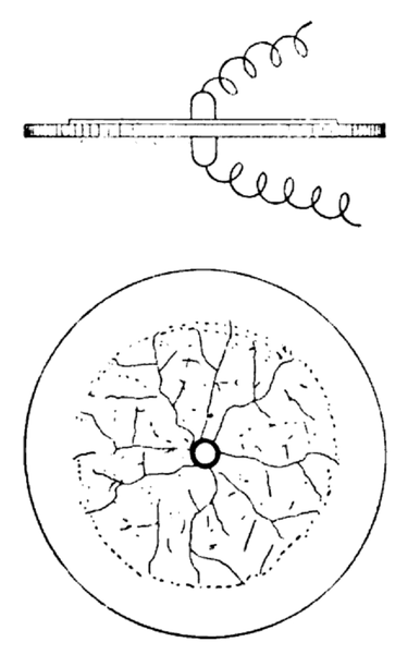 |
| Fig. 12 |
 |
| Fig. 13 |
 |
| Fig. 14 |
 |
| Fig. 15 |
If, instead of the pressure being applied to a small area, as in Fig. 11, the electrode be enlarged to a plate, as shown in Fig. 12, the same results will follow, but the spreading out of the ruptured air zone will on one side only and at a considerably lower tension.
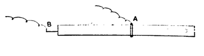
If pressure be applied to an insulating tube by means of a conductor inside and outside, as shown in Fig. 13, the air will fail at a certain tension, and the results will be similar to those obtained with the plate in Fig. 12. The streamers will start from the conductor on the outside at A and will run along the tube from the center towards the ends, the tendency being to cover the outer surface with an enveloping coating of ruptured air. In this, as in all other cases, the streamers are drawn out in such a direction as to increase the electro-static capacity.
If a still greater tension be applied, the streamers from A will finally draw sufficiently near to B to cause rupture of the air in bulk between B and the ends of the streamers extending from A.
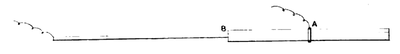
If, under these conditions, the internal conductor be now removed from the tube, as shown in Fig. 14, the air about the point A will no longer be ruptured, and the streamers will cease, although the distance between A and B and the conditions for surface leakage remain as in Fig. 13. It will now require a material increase of tension to cause a breakdown between the electrodes, and this will occur essentially as if the tube were not present.
 |
| Fig. 16 |
 |
| Fig. 17 |
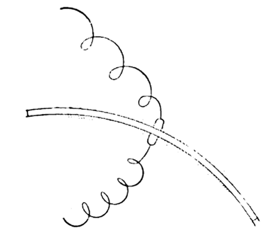
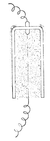
After initial rupture of the air, the spreading of the streamers is effected to a degree by the form of the solid dielectric. Fig. 15 indicates tension as applied to a dish of uniform thickness; Fig. 16 to a deep receptacle; and Fig. 17 to a special form. The results obtained from the arrangement shown in Fig. 15 will not differ materially from those obtained from the arrangement shown in Fig. 11 or, if one stir-face be made conducting, from those obtained from the arrangement in Fig. 12.
In the case of Fig. 16, however, the air in the interior of the receptacle around the entering conductor becomes ionized at sufficient tension, and the conditions then existing are the same as if the receptacle were filled with a conducting substance. With the arrangement in Fig. 17 the streamers start as in Fig. 11, but upon reaching the downward projection they are forced along its surface and away from the streamers on the upper face of the plate, until a point is reached where the electro-static field is no longer sufficient to rupture the air, when the streamers die out and further spreading of the ruptured air zone ceases.
All line insulators are made from variations of the forms just discussed. Surface insulation has little to do with their performance, and unless the faces be made conducting by a coating of water or other foreign material, the surface leakage may be neglected altogether from an engineering standpoint. A wet surface, however, is practically equivalent to the metallic coating illustrated in Fig. 12. For high tensions, wet surfaces ought to be considered as conductors; but dry surfaces need be treated only in relation to the electro-static phenomena already described.
A first consideration in connection with the design of a line insulator is its ability to maintain dry surfaces under all weather conditions. It has been frequently assumed that rain descends at an angle not exceeding 45 degrees from the vertical, hut this is not a safe basis for design. When rain is accompanied by wind at high velocity, and especially if the air currents be unsteady and in gusts and subject to deflection on account of the irregular contour of the country, it will then be found that at times the rain travels practically in a horizontal plane. As the rain-drops are often moving at high velocity, there will be also considerable splashing of the water where it meets obstructions, and this must be considered in predetermining the dry surfaces. With insulators of the "umbrella" type, there frequently results a wetting of a portion of the underside of the main petticoat from water splashed from other parts. The shape of the insulator may also result in deflecting the air currents, thus carrying the rain to surfaces that otherwise would remain dry. Insulators of the "Italian" and "double-story" types are frequently effected in this way. Those of the vertical, petticoat type are especially free from this defect, as the spaces between the petticoats are efficient in preventing eddying air currents from carrying moisture to the under side of the insulators.
After determining the extent of the possible wet surfaces, consideration ought to be given to the distribution of potential on the various parts of the insulator. The tension is applied between the point where the conductor is attached and some other point, depending upon the construction employed. During rains, the entire upper surface of the insulator is at the potential of the conductor, and the ground potential is, at the least, directly under the insulator at the cross-arm. This condition holds with wooden construction as well as with metal.
If a conducting pin be employed, the ground pressure will be carried still higher, and the tension will be applied across the comparatively thin material of the upper part of the insulator. The dielectric will then consist of the porcelain or glass at this point and the air adjacent to the conductor and pin. The tension will be that to the ground and, for a three-phase circuit under normal conditions, will be less than the pressure between conductors: but as there are many operating conditions where full tension may be applied to the insulators, it is better practice, for the purpose of design, to assume that this is the case at all times. The form of the pressure curve also has an effect, as it is the maximum tension at the peak of the curve that causes initial failure of the dielectric.
If the tension as applied sets up through the material an electro-static field sufficiently powerful, the air in series with the solid insulating material will be ruptured, and brush discharge and streamers will form, which, unless checked, may extend over the entire insulating surface, causing short circuit. The spreading of the conducting zone of air may be prevented, as previously explained, by the use of very large surfaces, or by employing deflecting projections or petticoats, so arranged as to reduce locally the strength of the electrostatic field to a point at which the air will not be ionized. These methods, however, serve only to stop the spreading of the ruptured air zone and require considerable dimensions for even low factors of safety. All brush discharges are wasteful of energy and are destructive of organic materials. It is brush discharge combined with capacity-charging current that has caused the burning of pins on high-tension lines.
Common wooden pins are practically conductors for high tensions, and the ground pressure is carried up within the insulator. When the pins possess dielectric qualities comparable with the material of the insulators, the tension may be said to be applied between the top and base of the insulator, resulting in a greatly increased thickness of the dielectric material. This usually overcomes brush discharge and materially increases the reliability of the insulator. For the best results, insulators for high tensions ought to be so designed that under no operating conditions would the electro-static field of force ever be sufficient to rupture the air adjacent to the insulating surfaces. This can be accomplished by properly proportioning the thickness of the material exposed to the electric stress.
The general dimensions of the insulator ought, of course, to be such that the direct air path from the conductor to the cross-arm will be sufficient to avoid failure through the rupture of the air in bulk. This is a matter of simple determination, involving only the length of the air path and the dielectric strength of the air in bulk at the extremes of pressure and temperature, as found in service. When insulators are made of several parts cemented together, the dielectric material is no longer homogeneous, and the distribution of the electrostatic strain may be materially altered.
The cements commonly used, such as sulphur, litharge and glycerine, Portland cement, and the like, possess entirely different and inferior electrostatic qualities to the glass or porcelain of which the insulators are made. The cement between the sections is in series with the dielectric material of the insulator, and is exposed to the same electro-static field of force. The strata of cement in some cases redistribute the electro-static charge. Under other conditions, the pressure is conducted directly to the cement through the ruptured air. In this case the semi-conducting cement becomes charged with practically the full terminal pressure, and excessive tension may thus be applied to a section of the insulator not designed to withstand it. This frequently results in sectional breakdowns, and the insulator fails in detail.
The irregular distribution of surface potential also affects the outside air path and, in some types of insulators, reduces the tension required to rupture the air between the points of applied tension. When insulators are made up of several parts, the cement employed ought to possess dielectric qualities comparable with those of the component parts, and every effort ought to be made to render the dielectric material homogeneous, so that there may be a uniform fall of potential between the points at which the tension is applied.
The resistance to disruptive breakdown or puncture of the solid dielectric is also of importance. Good porcelain or glass, however, has such great strength in resisting puncture that if the insulator be designed so as to entirely avoid rupture of the air near the points of applied tension, it will be impossible to puncture the insulator under operating conditions. One-piece insulators of glass or porcelain seldom fail from puncture, even if thin at the top, but two or three-part insulators sometimes fail by the puncturing of one or more of the sections, probably owing to unequal distribution of potential, as previously discussed.
Of the various substances available, glass and porcelain have been used almost exclusively for high-tension insulators. Glass has excellent dielectric qualities and can readily be obtained in desirable shapes at reasonable cost. Its greatest defect is its mechanical weakness, which is due almost entirely to internal strains developed during manufacture. Consistent design of the surfaces to obviate as far as possible shrinkage strains and careful annealing have improved the conditions of many glass insulators so as to render them reliable for service, but they still do not possess the mechanical strength of the best porcelain. Glass, however, is a more reliable dielectric material and, from an electrical standpoint, gives better and more uniform results. The best porcelain has great mechanical strength and good dielectric qualities. It is, however, difficult to manufacture in considerable thickness and is very apt to develop flaws and surface cracks. Common grades of porcelain are unreliable and ought not to be used for high-tension work.
While the insulator has been considered chiefly as an electrical device, it is still essential that it be treated as a mechanical support for the conductors, which function it chiefly serves. Practically all the mechanical strains on the insulators and pins are transmitted from the conductor. When the line is level and without angles and when the spans are equal, the strains are due only to the wind and weight of the conductor. When angles in the line occur, a transverse strain is developed. If the line be not level or the spans not equal, strains, having vertical and horizontal components, are produced. All the necessary calculations for the forces acting and the resulting strains can be readily made by the ordinary rules of mechanics and do not here require consideration. The following examples of high-tension insulators were selected as representing American practice:
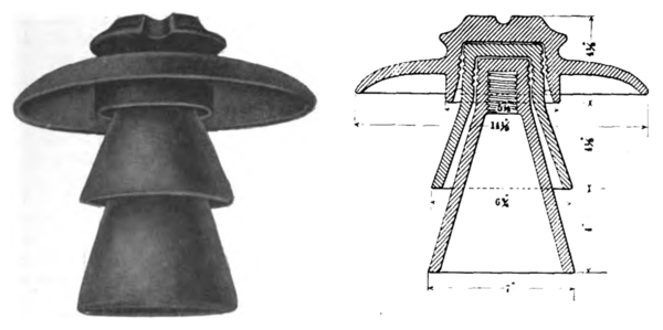 |
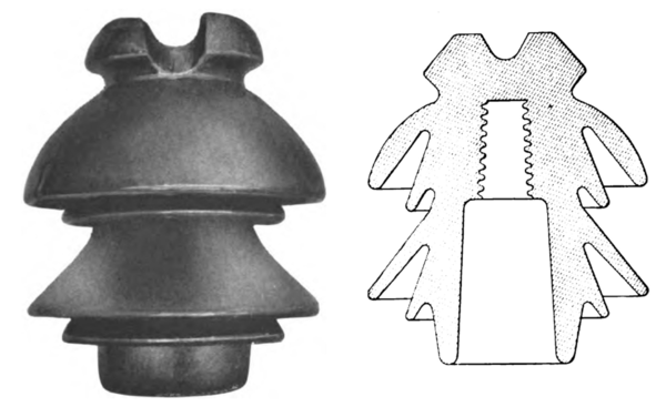
| Figs. 18 and 19. -- Brown Glazed Porcelain Insulator Made by the Locke Insulator Manufacturing Company, of Victor, N. Y., for the Washington Water Power Company, Spokane, Wash., and the Standard Electric Company, of California, for Carrying 60,000 Volt Currents |
Fig. 18 shows a brown-glazed, porcelain insulator, of the "umbrella" type. It is made in three parts cemented together, as indicated in the section drawing, Fig. 19. It weighs about 20 pounds. This insulator is in use by the Washington Water Power Company, already referred to in this paper.
 |
| Figs. 20. and 21.A Glass \"Umbrella\" Type Insulator |
Fig. 20 is a general view and Fig. 21 a section of a glass insulator, also of the "umbrella" type. It is made of two parts cemented together and weighs 13 pounds.
 |
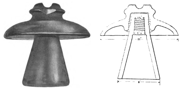
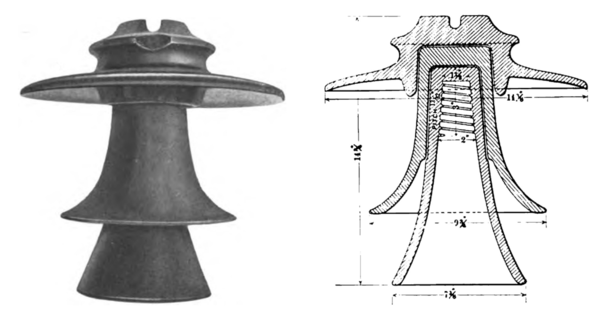
| Figs. 22. and 23. White Glazed Porcelain Insulator, Carrying 53.000-Volt Current for the Shawinigan Water & Power Company, Canada. Made by the R. Thomas & Sons Co., East Liverpool, Ohio |
Fig. 22 shows the insulator in use by the Shawinigan Water & Power Company, now operating at 53,000 volts. It is of white-glazed porcelain, in three parts. Its dimensions are given in the section, Fig. 23. This insulator also weighs 13 pounds.
 |
| Figs. 24. and 25. -- Single - Piece Brown Glazed Porcelain Insulator |
Fig. 24 is a single-piece insulator of the "Italian" type. It is made of fine porcelain, brown-glazed, and weighs 7-3/4 pounds. Fig. 25 shows its section.
 |
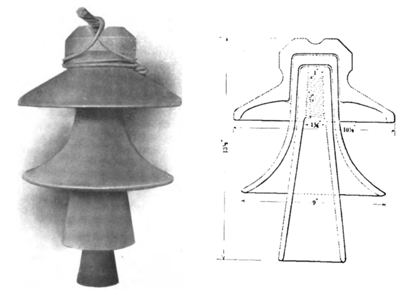
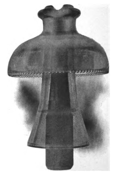
| Figs. 26 and 27. A Brown Glazed Porcelain Insulator of Late Design |
Figs. 26 and 27 show a porcelain insulator of late design. It is brown-glazed, is made in three parts and weighs 26 pounds.
 |
| Fig. 28. -- One of the Insulators of the Missouri River Power Company, Made by the Hemingray Glass Company, Covington, Ky. A Sectional View of This is Given in Fig. 10 |
Fig. 28 is the standard insulator of the Missouri River Power Company and is in regular service at 57,000 volts. It is of glass, is made in two parts, and has already been shown in section in Fig. 10. Its weight is 12-1/2 pounds.
The developments in the construction and insulation of high-tension lines have now reached a point where no doubt exists regarding the practicability of transmitting energy at tensions approximating 60,000 volts. From this time on it will be rather a question of expediency and engineering detail to determine the best methods of obtaining the desired commercial results. For pressures above 60,000 volts the field as yet is unexplored, but those who have followed this subject carefully agree that much higher tensions will ultimately be employed. The practices discussed in this paper cover what has already been accomplished, but seem also to point the direction for future development in this branch of engineering.
