[Trade Journal]
Publication: Electrical World and Engineer
New York, NY, United States
vol. 44, no. 14, p. 553-558, col. 1-2
The Puyallup River Water Power Development Near Tacoma, Washington.I.
GENERAL PLAN OF DEVELOPMENT.
THE cities of Seattle and Tacoma, Wash., and their suburban towns have in five years increased in population from 130,000 to upwards of 225,000; the growth of manufacturing industries and construction of street and interurban electric railways has kept pace with the increase of population, and to supply the consequent demand for electric power an unusually large generating plant of the most modern type has been constructed on the Puyallup River.
The Puget Sound Power Company, the owner of the plant now described, was organized in the year 1902, for the purpose of developing water power for use by the Stone & Webster properties in Seattle and Tacoma. Before beginning the construction of the plant a careful investigation was made of the variations in the flow of the several rivers in western Washington and the other features which would affect the reliability of the service obtainable from each; and a general plan was then adopted for the development of this power on the Puyallup River with an initial installation of 20,000 hp, the plans being made and the greater portion of the work carried out on the basis of continuing the initial installation to an ultimate development of 40,000 hp.
The design consists of diverting the Puyallup River just below the junction with the Mowich and carrying the water by means of a flume ten miles to a reservoir located on a high plateau, thence discharging by means of steel pipes against wheels in the power house under a head of 872 feet; the water-wheels so driven to be direct connected to electric generators and the current so produced to be transmitted at a pressure of 55,000 volts 48 miles to Seattle and 32 miles to Tacoma.
| |||
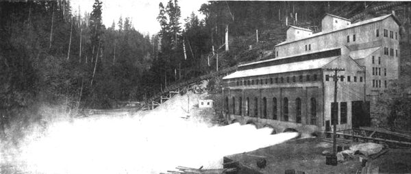
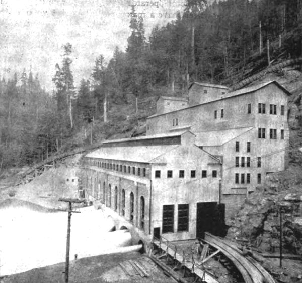
| Fig. 1. West View of Power House, Showing Four Generators in Operation,, Also Showing Temporary End Wall,, Also Grading and Trenching to Right to Facilitate Installation of Four Additional Penstocks and Generators. |
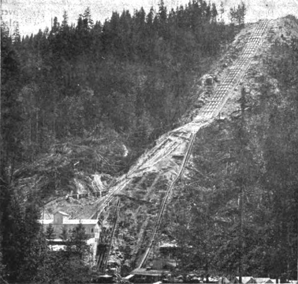
All water rights and the necessary land abutting on the river from the point of diversion to the point of return were secured, also all land necessary for flume and other structures, and the actual work of development was commenced March 1, 1903. To facilitate construction a spur track 25 miles long was built from the Payowsin Station of the Tacoma Eastern Railroad to a new station at Electron and continued a mile farther to the power house site. From Electron a standard gauge cable incline was built to lift to an elevation of about 950 feet to the reservoir site above the power house, and a wagon road to the head works. The first generator unit of 5,000 hp was put into commercial operation delivering power to Seattle and Tacoma on April 14, 1904, less than fourteen months after work wag commenced. The plant was put into complete operation for its initial installation of 20,000 hp on July 23, this year.
SOURCE OF SUPPLY.
The Puyallup River has its source in the glaciers of Mount Rainier, the highest mountain in the United States, and one of the great mountain peaks of the world, covering 200 square miles and rising 14,500 feet above the waters of Puget Sound. That part of the mountain higher than 5,000 feet above sea level is covered with snow and ice, and the precipitation resulting from the moisture-laden air of the Puget Sound region coming in contact with the glacial cold of the mountain sides is estimated to average 140 inches per annum. The fields of ice and snow which result from this precipitation are constantly descending the mountain sides to the valleys about its base in the form of slowly moving glaciers many square miles in extent, which fill the valleys to the depth of hundreds of feet, and are constantly added to from above as they melt away below.
These masses of ice increase in size and depth each winter and decrease under the heat of summer so that the hottest and driest days of summer produce the greatest rate of melting. The Puyallup and Mowich Rivers drain a fan-shaped section of the mountain and five of the glaciers described, flow thence through mountain ranges which add greatly to their volume, each for a distance of about 12 miles from the glaciers, and then join together, the combined river being then known as the Puyallup. The watershed of these rivers includes a rough and heavily timbered country not covered with ice or snow and below the very high mountain range. The streams of this lower timbered country are fed by the copious rains of the Puget Sound country which occur during the fall, winter and spring months concurrently with cool weather. During such weather the rain and the run-off in this timbered section is heavy and at the same time snow and ice accumulate on the mountain and the run-off from it is comparatively small. When the warm weather comes the rain and the run-off from the timbered section is at a minimum and the melting of the snow and ice on the mountain and the run-off from the same is at a maximum. This balance or alternation of the heavy run-off from the timbered and ice sections results in a remarkably uniform flow in the river at the point from which the water is taken for power purposes and makes the operating conditions in using this stream ideal.
Although the dam and intake are located within to miles of the nearest glacier, the elevation at this point of diversion is only about 1,700 feet above sea level and the climate at this elevation is so uniformly mild and the water flows so rapidly that no ice comes down the river nor is formed either in the flume or reservoir.
UTILIZATION OF CURRENT.
The power is used for all branches of servicelight, power and railway. It supplies the electric railway systems in Seattle and Tacoma, aggregating 168 miles of trolley road; the multiple unit, third rail line between Seattle and Tacoma, two cable roads, one in Seattle and one in Tacoma, furnishes power for numerous factories, together with the shops of the Northern Pacific Railway and the new pumping plant of the city of Tacoma, and supplies the greatest portion of commercial and residential lighting and street lighting in Seattle and in the towns between Seattle and Tacoma. Much of the power is distributed as alternating current, two-phase for power and single-phase for lighting; but there is also connected 10,000 kw of converting capacity for producing direct current, 2,000 kw of which is used for light and stationary motor supply. The bulk of the converting machinery (7,300 kw) being of the synchronous type, it is not necessary for the water-power plant to generate or transmit idle currents. The distribution of the current to the various localities and the transformation and conversion for various uses takes place at eleven sub-stations containing 26,000 kw of transformer capacity. Six of these are designed for transforming the 55,000-volt current to lower voltage and eight contain machinery converting to direct current for railway use.
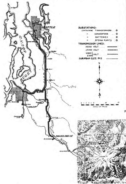 |
| Fig. 2 Map of Mt. Rainier and Transmission Lines. |
DAM AND INTAKE.
At a point one-half mile below the confluence of the Payallup and Mowich Rivers and about 1,700 feet above sea level are located the dam and intake of the Puget Sound Power Company. Here the water necessary for the operation of its plant is diverted by a low, solidly constructed dam, through a masonry intake to a flume which is constructed on the southwest side of the river for a distance of ten miles. The dam or diverting weir is 200 feet long and 5 feet high, and covers the bed of the river longitudinally for a distance of 60 feet, exclusive of the down-stream apron. It is built down to an impervious bottom of clay hardpan and is made tight by three rows of triple lap sheet piling set into hardpan bottom and bedded in concrete; it is faced with 6 x 12 timber, covered at the crest with 1/4-inch boiler plates, and besides the whole dam being a spillway there is a lower spillway 30 feet wide to localize the scour at the intake end. The intake is set at right angles to the dam and is constructed of concrete masonry. It is 62 feed wide at the river bank and is protected by a screen grating made of iron bars 1/4 inch x 4 inch x 6 feet spaced 2 1/2 inches. Provision is also made for the insertion of flash boards in grooves in steel frames in such a manner as to regulate or shut off entirely the intake at a point between the river and the grating. A radial gate of unique design is also installed at the junction of the masonry intake and the flume for the purpose of quickly controlling the amount of water delivered to the flume.
| |||
| Fig. 3. Incline Cable Railway for Hoisting Building Material Up 68 Per Cent Grade to Reservoir. |
THE FLUME.
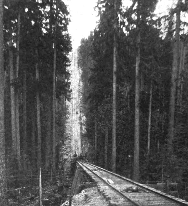
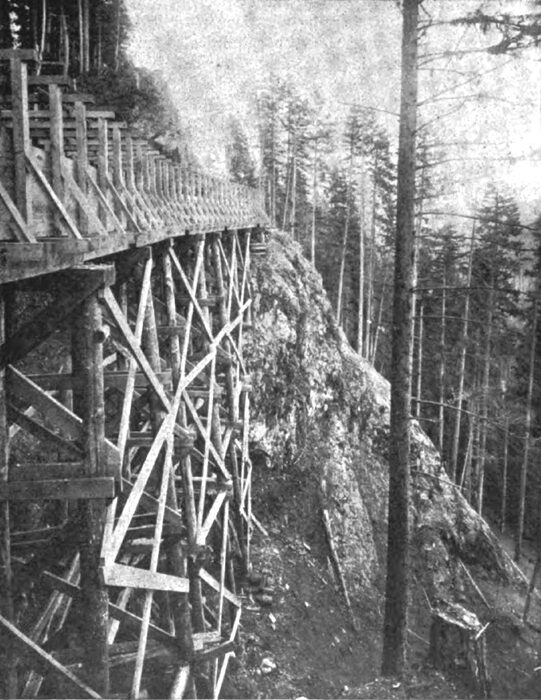
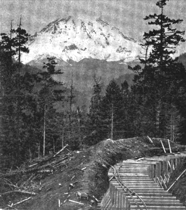
From head works to reservoir, a distance of about to miles, the water is carried in a flume which as now constructed is 8 feet wide and 5 feet high, inside measurement, but is framed for the addition of plank to make it 8 feet high. The flume is supported on low trestle work which follows the contour of the land. This trestle work is the same construction and of equal strength to that usually used for railroads, and in fact during the construction heavy work trans were operated over its entire length. The flume proper is constructed of surface planks 2 Ό inches in thickness and 12 inches wide, and the frames which surrounded it are spaced 4 feet centers; it is built on a uniform grade of 7 ½ feet to the mile. Sand boxes and automatic spillways are provided at various points along the flume and a number of gates are also provided for emergency use. A light railroad track for hand cars of standard gauge is laid along the top of the flume to facilitate inspection and repairs.
All danger timber along the line of the flume is being removed and the flume trestle is built on rock of hardpan foundation which protects it against trouble front slides. In constructing this flume the usual plan of building curves as a series of tangents was not followed. The bends in the flume are made with true curves, presenting a uniform and smooth interior surface and thus facilitating the flow of water.
| |||
| Fig. 4. Panoramic View of Water Inlet, Forebay and Partially Filled Reservoir. |
THE RESERVOIR.
The flume discharges its water into a reservoir located on a high plateau nearly 900 feet above the power house. This reservoir serves as a relay to maintain the plant in continuous operation, in case of interruption of water supply, and also serves the very useful purpose of supplying water for temporary overloads in excess of discharge capacity, or in other words, for equalizing the daily fluctuations of load. The location of the reservoir is particularly well adapted for the purpose, and the material excavated from the higher. Side of the, site was used to form the embankment on the tower side of the reservoir. This material is a glacial boulder formation of clayey consistency which required blasting before it could be handled with steam shovel. It paddled well and formed a watertight fill which set hard in the embankment almost like concrete.
The flume enters one end of the reservoir and, when the latter is drained, discharges into a concrete basin in front of the forebay. This arrangement permits the emptying of the reservoir for inspection or cleaning without interrupting the delivery of water to the power house, and distributes the water quietly to the penstocks without danger of carrying air into the pipes.
| |||
| Fig. 5. Panoramic View of Reservoir and Forebay Pool, Showing Simultaneous Operation and Construction. |
The forebay is of concrete, constructed inside the reservoir, and is divided into compartments forming separate gate chambers for the main penstocks. Each compartment is provided with iron racks or screens with stop boards to permit inspection or repairs without emptying the reservoir. The gates are arranged for connecting with an electric motor drive to be controlled from the power house. The depth of water in the reservoir is at all times shown at the power house switchboard by a Dibble automatic, electrical indicating and recording water gauge fitted with low-water alarm. This gauge is operated by three wires running from a float-actuated Dibble transmitter located in the reservoir.
| |||
| Fig. 6. Panoramic View of Head Works, Gate Tender's Lodge to the Right. |
PENSTOCKS.
The penstocks, one for the two exciters, one for each of the four generating units now installed and one for each of the remaining four units to be installed later, are carried through the reservoir embankment is the form of concrete-protected wood-stave pipes, joining the steel pipes just outside the reservoir embankment. Of the eight main pipes for the complete plant, four, together with the exciter pipe, are now continued about 1,700 feet down an incline of about 30 degrees to the power house on the river bank below. Each main pipe is of riveted steel forty-eight inches in diameter and Ό inch thick at the upper end, tapering to thirty-six inches in diameter and 4 inch thick at the lower end, and wan furnished by the Elation Iron & Locomotive Works. The penstocks are anchored by massive concrete abutments and all surface water is carefully drained away, and as a further security the pipes are protected with backfilling of earth on which is planted quick-growing vegetation.
POWER HOUSE.
The power house is built in the bank of the river on a foundation of piling and rocks. It is of massive concrete, brick and steel construction. The building for eight units will be about 100 by 266 feet, divided longitudinally into two parts, a generator house and a transformer and switching house. The generating units are arranged parallel to and along the riverside of the building, the penstocks being brought to them under the main floor from the rear. The transformers are grouped in isolated rooms of Concrete in the basement of the switch house, the switching apparatus and wiring being in compartments overhead, as hereafter described.
| |||
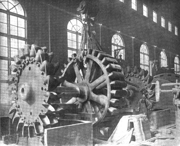
| Fig. 7. Placing Water-Wheel and Rotor Shaft in Bearings. |
WATER-WHEELS.
Each "unit" consists of two overhung Pelton water-wheels, 10 feet 6 inches in diameter, mounted on each end of the shaft of each 3,000 hp, two-bearing generator. The nozzles are of the needle type arranged for automatic deflection by Lombard type "L" governor for speed control, the operation of the needles being only for economic Adjustment of the discharge to the load of the machine. Each nozzle is also provided with a motor-operated gate valve for cutting off the water supply. The wheels have a maximum capacity of 7,500 hp for each "unit.
The wheels are arranged to be started and stopped and adjusted far speed from the main operating switchboard at one end of the generator room. Motor-driven pumps provide oil supply for ordinary lubrication, pressure oil for forced lubrication in starting, and circulating water to cool the bearings.
Two rotors and wheels are hydraulically forced onto a 24-inch hollow, nickel steel, fluid-compressed shaft. The spray from the Wheel discharges collecting in the water-wheel housing enters this hollow shaft and automatically serves to cool the bearings. At the date of their installation these were the largest impulse wheel units its the world.
GENERATING PLANT.
There are four General Electric revolving field generators of 3,500 kw capacity each, with an overload capacity of 25 per cent. for two hours, wound for three-phase current at 2,300 volts and a frequency of 60 cycles per second. Two 150-kw, 135-volt, 600-r.p.m., shunt-wound exciters are provided, each direct connected to an overhung Pelton water-wheel and to a 2,080-volt, 200-hp, three-phase induction motor. The wheels driving the exciters are not provided with automatic governors, and the direct-connected induction motors serve this purpose, operating either as motors or as generators according as they run below or above synchronous speed. The motors also afford a relay source of power for excitation in cast of failure of an exciter water-wheel or its water supply. Each exciter is capable of exciting six generators under all conditions.
There are three banks of transformers installed at the power station, each bank consisting of three 2,333-kw water-cooled, oil-insulated, General Electric transformers with 25 per cent overload capacity for two hours. Each bank has a capacity equivalent to two generators, the third bank being spare, so that the failure of even a complete bank would not diminish the capacity of the station. The transformers are connected delta on both the high and low tension sides, and the arrangement of the windings is such that, with 3,3oo volt, on the low-tension aide, high and low voltages of 27,500, 45,000 and 55,000 may be derived. These transformers have been operated at 55,000 volts from the beginning.
Water for cooling is derived from a spring above the power house, supplemented by connection with the reservoir. The transformers are piped so that the oil can be removed from the case into large storage tanks, and an emergency blow-off valve is arranged to discharge the oil quickly into the river.
Before filling these transformers with oil they were dried out at a temperature of 80 C. under a vacuum of 26 inches for 10 hours. No oil was used that did not stand a potential test of 40,000 volts between 1/2 inch flat electrodes placed 2-10 inch apart. After filling and allowing the oil to thoroughly settle, samples of oil from bottom and top of each transformer were subjected to the above potential test, and no transformer was put into service before the oil passed this test satisfactorily.
| |||
| Fig. 8 Camp 9, Superintendent's Cottage, Power House and Penstock Lines, Looking South. |
ELECTRICAL ARRANGEMENT.
For conducting each generator and transformer bank to the low-tension busbars, and each transformer bank and transmission line to the high-tension bus bars, a full complement of remote-control, motor-operated oil switches is provided. These are two sets of 2,300-volt bus bars, designated as the main and auxillary busses. The main bus is for regular operation, which the auxillary bus is for emergency operation, and for relaying the main bus in case of repairs to the latter. Both sets of bus bars are identical and any generator and any transformer bank can be connected to either set. Between each generator and each set of 2,300-volt bus bars there are two sets of disconnecting switches and a triple pole General Electric type "H", 1,200-amp, motor-operated oil switch, a set of disconnecting switches being on either side of the oil switch. Between each set of bus bars and each transformer bank there are two sets of disconnecting switches and a type "H", 3,000-amp, motor-operated oil switch, the arrangement being similar to that of the generator switches. The purpose of the disconnecting switches is to remove the potential from the oil switches so that inspection of or repair to the oil switches may be safely made. The disconnecting switches are not to be operated when carrying current except under emergency conditions. All ordinary switching is done by means of the oil switches, which simultaneously open and close the three legs of the three-phase circuit. In addition to the single pole, double-throw switches mounted on the operating panels, for opening and closing these switches, when cutting in or out a generator or transformer bank, there is for each oil switch a clock-type, time-limit relay actuated by secondary current from transformers in circuit with that switch, these relays operating the motor connected to the oil switch in case of an overload or short circuit lasting the period for which the relay is set. These relays can be set for overload periods of 4 seconds down to a small fraction of one second, it thus being possible to localize automatically short circuits on the system, and in the apparatus, without completely shutting down the system. The electrical arrangement of the motors driving the exciters is the same as that of the generators.
| |||
| Fig. 9. Flume Line Through the Rock Canyon of the Puyallup. |
| |||
| Fig. 10. End View of Power House. |
| |||
| Fig. 11. Partially Constructed Flume Line Showing Mt. Rainier in the Distance. |
There is one set of high-tension bus bars, divided into three sections by sectionalizing switches, each transformer bank being connected to a corresponding section, and one line to each of the end sections. Between the high-tension bus and each bank of transformers there are two sets of disconnecting switches and one triple pole General Electric, 60,000-volt, 400-amp., motor-operated oil-switch, a set of disconnecting switches being on either side of the oil switch. There are two outgoing high-tension lines and each line is controlled as just described for the transformer banks. All the high-tension oil switches possess the automatic features described for the low-tension oil switches.
Lightning arresters without reactance coils are provided for each outgoing line. Static dischargers are provided for the low-tension side of each transformer bank. These static dischargers consist of three 2,500-volt S. P. lightning arresters connected in star, the neutral point grounded. They limit the potential of the low-tension winding to 2,500 volts above ground, and would come into action in case of grounding of one side of the transmission line or transformers.
The control of all the oil switches is from operating signals erected on a gallery in the east end of the generator room, at an elevation of 14 feet above the generator room floor. The arrangement of panels from left to right is exciter panels, generator end; exciter panels, motor end; generator panels, totalling panel, generator panels, transformer control panels, high-tension line panels. The generator and exciter field rheostats are hung below the gallery and are operated from pedestals by means of shafting and bevel gearing, the contact plates being on the rheostat boxes. The highest alternating-current potential on the switchboard panels is 115 volts, derived from potential transformers, and the highest direct-current potential is 125 volts, derived from the exciters.
Each generator panel contains three ammeters, one voltmeter, a polyphase indicating wattmeter, a polyphase integrating wattmeter and a field ammeter. Each outgoing line panel contains three ammeters, and the totaling panel contains a power factor indicator, a frequency indicator, a curve-drawing voltmeter and three curve-drawing ammeters. The curve-drawing instruments belong to a type lately developed by the General Electric Company, giving a record three inches long per hour.
The control of the plant is completely from the switchboard gallery. A water-wheel may be started or stopped, a generator brought up to voltage, synchronized with other generators on either bus, a transformer bank cut in on either bus and a transmission line connected in circuit without the presence of a person in the room where the actual switching is done, the lighting of a red lamp indicating the closing of a switch, and a green lamp the opening of a switch.

