[Trade Journal]
Publication: Electrical Age
New York, NY, United States
vol. 33, no. 6, p. 434-439, col. 1-3
High-Tension Insulators
By V. G. CONVERSE
The best form and the limitations of the high-tension insulator are to-day still doubtful factors in electric transmission, but experiment and intelligent discussion are both helping toward a solution of the problem. An interested welcome is therefore extended to such contributions as Mr. Converse's, which was presented originally at the recent International Electrical Congress at St. Louis. Insulators are one of Mr. Converse's specialties, and what he writes about them makes excellent reading.The Editor.
IT is only fourteen years since 3000 volts were considered a very high tension, and the success of a transmission at this tension was looked upon with far more skepticism than is one of 80,000 volts at the present time. As the steps in high tension have been made with the increasing use of alternating currents, and as alternating-current power transmission dates back only the fourteen years mentioned, the province of this paper may then be considered to be within these limits.
It is a little difficult to trace the early stages in the development of the high-tension insulator. Undoubtedly the first forms were copied from insulators used for telegraph and telephone work. Certain it is that the same styles of insulators were proposed and the same theories were advanced. As the tension or voltage increased, the insulators were made larger and had various petticoats in order to prevent leakage of current. Since it was found in telegraph work that if the surface of the material of the insulators was hygroscopic there was difficulty in transmitting the message, the materials of high-tension insulators were very carefully considered in order that this dangerous hygroscopic condition might not so reduce the effectiveness of the insulator that vital quantities of current would leak over the surface. The same construction for cross-arms, pins, and the securing of insulators, adopted by the telegraph and telephone companies, was adopted for power transmissions, and until a few years the aim was to use such details of construction as had become standard and thus could be easily obtained.
Glass and porcelain are the only materials which have been used extensively for high-tension insulators, although many other materials and compositions have been proposed and tried. At times it has seemed as if one possessed qualities of decided advantage over the other, but a better understanding of the requirements or an improvement in the method of manufacture has brought the other to an apparently equal basis, so that from the first we have had glass insulators and porcelain insulators, and even combinations of glass and porcelain.
The commercial success of high-tension transmissions being until late years in doubt, developments of insulators have been in the improvement in form and materials, no radical changes in construction being ventured yet every engineer has had his own ideas regarding the details of construction. It would seem as if almost every engineer who has had the opportunity of exploiting his ideas, has done so. As a result, we have had at various times insulators with gutters and spouts, insulators in the form of helmets, some with drip points, and others with every conceivable form and combination of petticoats. The situation has been further complicated by a variety of ties for securing the line to the insulator, pins of wood and of iron, various threads for securing the insulator to the pin, and even by a wide range of colors of material. It is little wonder that the manufacturer of porcelain or glass who was skilled in the art of making tableware and various other utensils, and perhaps telegraph insulators, has hesitated when confronted by the requirements of the up-to-date high-tension engineer.
It should be stated to the credit of the manufacturer that the arts of making porcelain and glass, which have descended to us from periods antedating the Christian era, had reached a certain stage of perfection. Strong and beautiful and satisfactory wares were made, but here was a new requirement. The material of the insulators must be strong to withstand mechanical strains, and it must also withstand the unseen and unknown electrical forces which would tend to break it and render the insulators useless.
The improvements that have been made in glass have been in the direction of strengthening the quality in order to protect against mechanical breakage, the structure of glass already suiting electrical conditions very well. The improvements in porcelain which have been in the direction of strengthening the body of the material to resist electrical puncture have been interesting and are noteworthy. From porcelains, which were first furnished for insulators and would stand but a few thousand volts, the advancement has been in the line of obtaining a more homogeneous, refractory and vitreous grade of material which is strong in resisting electrical breakage. Of recent years the combining of layers of this high-grade electrical porcelain has further strengthened the body of the insulator.
 |
| Fig. 1 |
But let us trace directly the forms of insulators which have been used. In 1890 the first alternating-current power transmission in the United States used, for 3000 volts, a glass insulator of the form shown in Fig. 1. This is an insulator such as is commonly used by the telegraph companies and is only about 3 inches in diameter. In spite of the predictions that the insulator would not suffice, the plant continued in operation for six years without insulator troubles.
 |
| Fig. 2 |
For the famous Frankfort-Lauffen transmission experiments in Germany in 1891, a porcelain insulator with an oil cup was used. No definite information as to the exact shape of this insulator is at hand, but the principle was probably not unlike that of the insulator shown in Fig. 2. Voltages as high as 28,000 to 30,000 were used in these experiments for a limited time. Insulators with oil cups of various forms appeared very shortly afterwards in Great Britain and the United States. If the insulator was of glass, the outer petticoat was usually curved inward and up so as to form an internal groove which would hold oil.
A common form for porcelain insulators was a petticoat brought down from the body of the insulator which would dip into a cup of oil, the cup being made in a circular form and held in place around the pin by a support on the pin. Insulators with detachable oil cups were supplied for the 10,000-volt transmission at Pomona and San Bernardino, in California, started in 1892. The oil cups were not used, however, as they were found to be unnecessary.
 |
| Fig. 3 |
Insulators without oil cups being equally effective as those with oil cups. a form similar to that shown in Fig. 3, made of either glass or porcelain, came into use. Here the idea was to impede the leakage of current over the surface by introducing petticoats which gave a very long surface between the conductor and the pin. Some insulators had as many as four or five such petticoats.
No further increase in voltage is noted until 1895. when we find the Hochfelden-Oerlikon transmission in Switzerland at 13,000 volts. In 1897 we had transmissions in the United States at 16,000 volts. About this time it was found that porcelain insulators which had been formed and pressed in iron moulds had not a sufficiently compact or homogeneous structure and were apt to be punctured in service. A study of the matter showed that really the only effective dielectric insulation of the porcelain was contained in the glaze over the surface of the porcelain. In some cases it was found that the interior body of the porcelain insulator would actually absorb and hold a considerable quantity of water.
 |
| Fig. 4 |
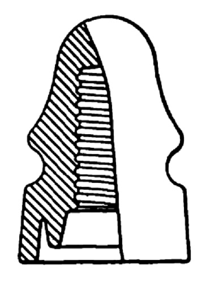
The manufacture of porcelain was then studied with a view to overcoming these difficulties. The method was resorted to of making the insulator in several thin shells which were glazed separately and then glazed and fired together, the potter's wheel being reverted to in order to make the shells of sufficient compactness. This construction is shown in Fig. 4. It will he noted that a petticoat is here extended down for a distance over the pin for the purpose of further insulating from the pin. Attempts had been made heretofore to extend a petticoat down around the pin, but when the insulator was made in a mould no such long petticoat could be made as is now possible when the insulator is made in several parts.
 |
| Fig. 5 |
In 1898 we have the first commercial very high-voltage plant in operation in the United States, at Provo, Utah. This transmission is at 40,000 volts, the insulator used being of glass, shown in Fig. 5. This insulator has outwardly extending petticoats, the purpose of these being to provide unexposed surfaces near the wire in order to prevent surface leakage.
 |
| Fig. 6 |
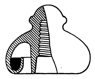
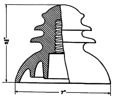
In 1900 the demands of the Bay Counties and Standard Electric Companies of California, for 60,000 volts, made necessary a very much larger insulator than had ever been made before. This is shown in Fig. 6. In this insulator the outer petticoat is carried out almost horizontally, and a gutter is formed on the top near the edge of the petticoat to conduct water away from the cross-arm. The top piece of this insulator was originally of porcelain, and the petticoat around the pin, which now amounts to a sleeve extending clown the whole length of the pin, was of glass, the glass and porcelain being secured together by sulphur at first and then cement. This type of insulator has been commonly designated the "mushroom" type, from its appearance. A modification of the outwardly extending petticoat idea is seen in the insulator shown in Fig. 7. This form has had a limited use.
 |
| Fig. 7 |
While the insulators enumerated have been referred to in order to show the successive steps in the development of the present highest-tension insulators, it must not be understood that such insulators are not still in use. On the contrary, with the exception of the oil insulator, all of these types, and many others possessing the same essential characteristics, are in service at the various voltages for which they have been found adapted. Even the telegraph insulator shown in Fig. 1 has given good service in certain localities at voltages as high as 10,000.
Insulators of the types shown in Figs. 3, 4, 5 and 6 are in use for voltages as high as 40,000. In various sizes these insulators are used for all intermediate voltages up to 40,000. The types shown in Figs. 5 and 6 are in use in a few cases at 45,000 volts. Some of these insulators have given good service from the first, while others have failed, owing largely, it is believed, to faulty material. In some cases it has been necessary to replace a whole equipment of insulators because of their faulty construction; in other cases a gradual weeding out has been necessary until the faulty insulators were removed. Occasionally we hear of a plant operating where there has been almost no trouble with insulators, except with such as have been broken by outside interference. In general, the feeling is believed to exist that the line-insulator problem for voltages as high as 40,000 has been satisfactorily solved.
 |
| Fig. 8 |
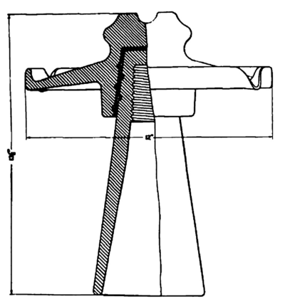
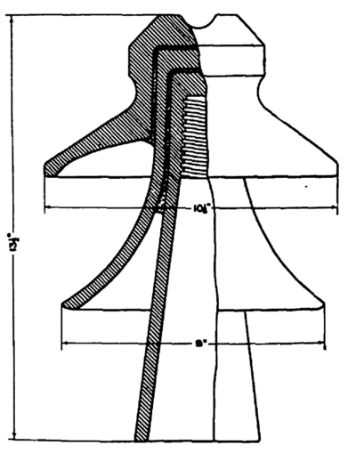
We are now at the point of consideration of insulators for the very highest voltagesthose which are in use for voltages of from 50,000 to 60,000. Fig. 8 shows a glass insulator used by the Missouri River Power Company, in Montana, for 55,000 volts. This insulator has been in service since 1901. The insulator is in two parts,one a hood, 9 inches in diameter; and the other a sleeve set over the pin. The sleeve, which is open at the top, adds nothing to the dielectric strength of the insulator, its purpose being to protect the wooden pin. Obviously the sleeve would be of little value if a metal pin were used. This type of insulator possesses the advantage of being in two separable parts, either of which can be replaced if broken.
 |
| Fig. 9 |
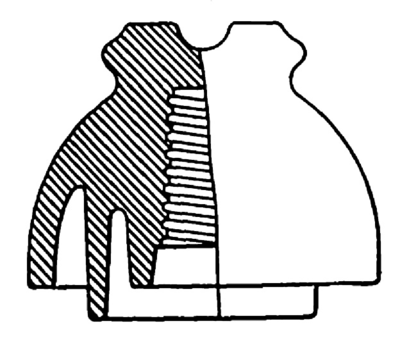
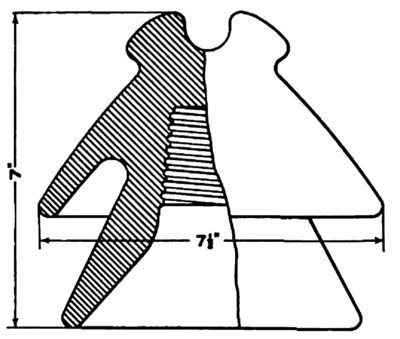
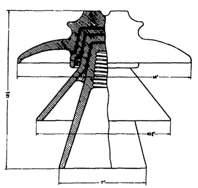
The insulator used for the 50,000 volt transmission at Shawinigan Falls, Quebec, is shown in Fig. 9. This is of porcelain and made in sections, each of which has a closed top and adds to the dielectric strength of the insulator. Two petticoats, one 9 inches and the other 10 inches in diameter, extend outward and give the effect of one insulator over another. One section extends down around the wooden pin and serves to protect the pin. The sections are held together with Portland cement. This insulator shows the combination of the sleeve around the pin, outwardly extending petticoats, and sections, as first indicated in Figs. 4 and 5.
 |
| Fig. 10 |
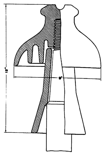
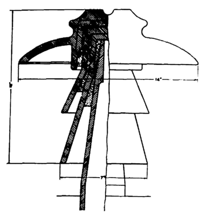
Fig. 10 shows a very large and extended form of the mushroom type. which has recently been put into use on the 60,000-volt transmission at Guanajuato, Mex. The top section is 14 inches in diameter. The sections are secured together with Portland cement and the whole is cemented to a hollow metal pin. For several transmissions under construction for voltages between 50,000 and 60,000, the insulator shown in Fig. 11 has been adopted. Some of these insulators exceed 14 inches in diameter and weigh as much as 25 pounds.
Abroad, insulators arc used which are similar to those used in the United States. It is probable, however, that they have not been made in such large sizes, and also that corresponding sizes are used for lower voltages.
 |
| Fig. 11 |
The present insulators for the highest voltages, then, of which the writer knows, and which may be considered as representing the most advanced state of the art in insulator design and construction, are represented in Figs. 8, 9, 10 and 11. Whatever advantage one may possess over the other will doubtless be shown in course of time.
Compare now the telegraph insulator, which was used as the first high-tension insulator, with these large ones. Our high-tension insulator has grown with increasing voltages from one weighing a pound or two to one weighing 25 pounds, and from 3 inches to 14 inches in diameter, and in cost from a few cents to several dollars.
We naturally begin to wonder what the future development in insulators will be. Will they continue to increase in size and in weight? If so, we can easily imagine that when an insulator 14 inches in diameter and weighing 25 pounds is required for 60,000 volts. 8o,00o volts might require an insulator 20 inches in diameter and weighing 50 pounds. Further development along this line brings to our imagination insulators which will look not tin-like Chinese pagodas and weigh perhaps several hundred pounds, as has been predicted.
This development appears ridiculous when we consider such structures made out of fragile materials like glass or porcelain, yet it is believed that much higher voltages are to be used in the future. Even now we find one company in the United States equipped in every way, except as to insulators, to transmit at 80,000 volts. We note also that the largest power development now in progress is providing to receive apparatus for 80,000 volts, the amount of power in this case being so large that it has been considered impossible to always market it within the range of territory to which it may he economically transmitted at less than 80,000 volts.
Another factor which is tending to make insulators heavier is the steel tower construction for supporting the lines. This construction means longer spans and hence heavier and stronger insulators. Some relief may be given to the insulators on these towers by housing them over to protect them from the elements. Some slight advantage may also be gained by securing the wire to the under portion of the insulator, rather than on top of the insulator, as is now done.
It would seem, however, that the trend of development in high-tension transmission would continue along the lines which have become established. In favor of the further increase in voltage, it must be remembered that there is always the possibility of the discovery of some new insulating material which is superior to glass and porcelain; and much improvement may he expected even in glass and porcelain themselves. While a remarkable improvement has been made in the dielectric strength of porcelain, it is only at the present day that the possibilities are beginning to be realized. Likewise with glass, we may expect a complete revolution in the method of manufacture, the art of making glass insulators having been given less thought and probably being much less advanced than the art of making porcelain insulators.
The requirements for a high-tension insulator may be enumerated as follows:--
1.The material must have a high dielectric strength; in other words, it must be strong to resist puncture by the current. In order to fulfill this condition, the material must be continuous, compact and homogeneous, even the most minute crack or fracture being a weakness.
2.There must be sufficient resistance over the surface of the insulator so that there will be no considerable conduction or leakage of current.
3.The distance around the insulator between the wire and the pin or support must be sufficient to prevent the current from arcing.
4.The second and third requirements are dependent upon the shape of the insulator. Its contour must be such that there will be unexposed stir-laces which will not get wet or accumulate dirt or salt, as these materials are conducive to leakage and tend to lessen the arcing distance. Evidently the requirements which are dependent upon climatic conditions vary with the locality in which the insulators are to be used. If in a country which is not subjected to heavy rains, sleet or dust storms, the insulator may perhaps be smaller than an insulator required in a locality where the climatic conditions are severe. Usually a larger type of insulator is required for the same voltage in a cold country than in a warmer climate. This may explain why some insulators which have been very satisfactory under a given voltage in one locality have utterly failed when tried at the same voltage in another place. In some localities, particularly on the Pacific Coast, the accumulation of salt is so great from the so-called salt fogs that it has been found necessary to have the unexposed surfaces rather shallow and with few petticoats in order that the surfaces be readily accessible for periodical cleaning.
5.The shape and arrangement of the petticoats should be such that the electrostatic capacity of the insulator will be small.
6.The internal heat losses from conduction and hysteresis should not be such as to appreciably heat the insulator.
7.Mechanical requirements, such as strength, mounting, method of fastening the wire, and color, are, in general, dependent upon the conditions to be met.
It does not seem as if details, like gutters, spouts, drip points, and the like, can be considered of much value. They are features which may look well in theory, but can cut but little figure in practice. Certainly the insulation of high-voltage lines is more dependent upon a good, strong insulator with liberal margins of safety, than upon such refinements.
The following tests are advised in order to determine whether insulators will meet the requirements:
1.---In order to determine dielectric strength, porcelain insulators should be inverted, with their heads dipping into salt water, the solution extending-well over the head of the insulator. The hole for the pin should also be filled with salt water. The predetermined voltage for testing may then be applied to the two salt solutions. Usually a voltage test of several minutes is made. The defective insulators will be punctured in this manner. If the porcelain insulators are made in several sections, the purpose of the sections being to obtain greater dielectric strength, then the sections should be tested individually in the same way. When the sections arc cemented or as-sembled to complete the insulator, it is advised to again test, using the same method, in order to be certain that the sections have not been broken. Every porcelain insulator of a lot should be tested in this manner.
 |
| Fig. 12 |
If the insulators are of glass, it is best to have every one tested in the manner described for porcelain insulators, but as the defects in glass are easily visible, it may be necessary to test only a few of a lot in order to determine the strength of the glass, the remainder passing the rigid examination of an inspector, who will discard such insulators as have cracks, air bubbles, or less than the required thickness.
2.The measurement of leakage over the surface of an insulator is an extremely difficult thing to accomplish, and the refined methods which are required are not applicable to factory tests of a large number of insulators. Any leakage of account will be observed in the test for dielectric strength, either by the visible creepage of the current over the surface, or by the heating of the insulator.
3.A lot of insulators having passed a preliminary inspection, it is necessary to test only a few in order to meet the third requirement. These may be set up as if in service and the predetermined voltage applied. It is customary to apply the voltage to the line and pin. It is further advised that the voltage be applied across two insulators mounted in the same way in order to duplicate as near as possible normal running conditions.
4.In order to test for the effectiveness of the contour of an insulator, it is necessary to imitate as nearly as possible the most severe climatic conditions under which the insulator is to operate. Tests of this kind have not been extended farther than to obtain the effect of a heavy driving rain. An insulator mounted as for use should have a broken spray of water thrown upon it at an angle but slightly above the horizontal. The results of this combination may then be noted with a predetermined voltage applied between line and pin, or between two insulators similarly treated.
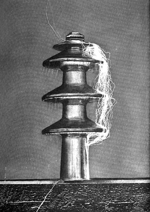
| |||
| Arcing at 118 and 157 Kilovolts Under A Spray of Water |
The value of tests should not be overestimated, for it will be recognized, especially as to dielectric resistance, that no laboratory or factory test of the dielectric strength of insulators can approach the time test of insulators in actual service. Consequently it is well to allow a wide margin of safety over the actual requirements. Wide margins of safety in every particular are also good practice in order to compensate for the abnormal voltages which are characteristic of high-tension transmissions. It is questioned whether there is any other element of a high-tension power transmission which operates on such narrow margins as the insulator. Especially is this true in America.
| |||
| Arcing at 198 Kilovolts Under A Spray of Water |
Unfortunately, with very high tensions, we are apparently nearing the point where the question is whether there is any margin possible, rather than how much. For a better understanding of the situation, the writer will review the conditions as he has found them.
The electrical requirements of a high-tension insulator are at variance with the requirements for mechanical strength in the following respects:
1.In order to increase the dielectric strength, reduce the capacity and lessen the brush discharges, it is necessary to increase the thickness of the head of the insulator. As the thickness is increased, the pin or support in the insulator is removed farther from the strains of the wire, and mechanical stresses are brought upon the insulating material which it is incapable of withstanding. Especially is this true if the wire is tied or supported on the top of the insulator.
2.--If the point of support of the wire is lowered to the side of the insulator, it is necessary that the insulator be of large diameter at the point of support in order to have the required dielectric thickness. Also with the wire on the side of the insulator, the surface distance is decreased and the length of the adjacent petticoat must be correspondingly increased.
3.No logical or safe arrangement has ever been proposed whereby all the lines of a circuit can be supported otherwise than on the tops of the insulators. In this position the surface of the insulator is exposed to the elements, at least as far as the edge of the extending petticoat adjacent to the line, and the effect is to aggravate the cause for leakage for a certain distance, where it must be checked.
4.The requirement for a larger insulator means one which is more breakable; if of glass, one apparently beyond the present knowledge of how to mould, or how to anneal.
The electrical requirements are also contradictory in this respect, that a larger insulator for increasing the arcing distance adds but little resistance to leakage and probably increases the capacity.
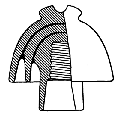
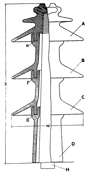
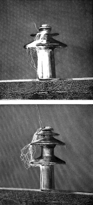
The writer early foresaw the objections to making insulators of constantly increasing diameters for increasing voltages, and proposed the making of insulators in parts and with outwardly extending petticoats. Such construction is shown in Fig. 12. Other forms of insulators embracing the essential features have already been shown, as in Figs. 9 and 11.
The purpose of the construction of the insulator shown in Fig. 12 was to study the effect of the outwardly extending petticoats in resisting arcing of the current between line and pin. The exact details of construction are a top piece, A, screwed onto a wooden pin, H; two like sections, B and C, and a supporting section, D, resting on the cross-arm or support, and holding B and C, D also serves the purpose of protecting the pin.
The grooves at e, f and g are for holding an insulating medium, if desirable to insulate between the several parts. These parts being readily separable, it is easy to assemble A and D, or A, D, and either B or C. Sections A, B and C were 10-1/2 inches in diameter, and the whole insulator when assembled, as shown in Fig. 12. was 23 inches high from the cross-arm. Under test, the terminals of the testing apparatus being connected at the point for the wire and at the cross-arm, the current arced around at the following voltages:
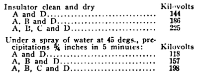 |
No insulating material was used in the grooves during these tests. There was no tendency for the current to arc between the sections, and there were no serious discharges up the inside of the sections or in the grooves between the sections. This experiment is considered of importance in that the addition of each outwardly extending petticoat section requires a nearly equal additional voltage to produce arcing. The advantage of a properly proportioned insulator with outwardly extending petticoats is evidently less diameter for the same resistance to arcing around than an insulator of the mushroom type.
As to the surface conditions on insulators of glass and porcelain, no differences have been noted in the conduction or leakage of current. With high tensions, such water or moisture as falls on the insulator is quickly dispelled or dried off by the leakage of current, high tensions tending always to keep an insulator dry. In general, losses on high-tension insulators, until a brush appears, are so small that they are negligible. With the brush the losses increase very rapidly with increase in tension.
There remains for the investigator an almost unexplored field for the determination of how the potential may be distributed through an insulator: and not until such knowledge is had may we expect to know the form of the rational design, and learn of the limitations of the high-tension insulator.
