[Trade Journal]
Publication: American Electrician
New York, NY, United States
vol. 17, no. 1, p. 9-12, col. 1-3
·
·
[Missing text]
·
·
notice the exhibit shown in Fig. 18. This shows a pole-top that had been burned away and the insulator and pin. When the pole was found it had been burned as shown, but the insulator and pin were still in position, being held there evidently by the winding of galvanized wire, while the zinc wrapping had protected the pin and thus kept the insulator from falling. The lesson to be drawn from this exhibit is obvious. The entire line to Stockton consists of No. 1 B. & S. gauge seven-strand bare aluminum wire, weight 401 pounds to the mile. Soft aluminum wire is used for the wires and the poles are set 180 ft. apart. For the Folsom line No. 4 medium hard-drawn copper wire has been used with No. 6 annealed copper tie wires. On account of the greater weight of the wire the poles on this line are set 135 ft. apart. The company installed both aluminum and copper lines so that it could observe the working results of both under similar conditions and determine which was the best material to use for future extensions. Thus far the wires have not been in operation long enough to give conclusive results.
Fig. 14-E is a view of the company's Folsom sub-station and shows how the 11,000-volt and 2200-volt secondary wires are carried up and over a steam railroad track and two pole lines of another transmission company. The poles are of sufficient height and close enough together so that a broken wire will not come in contact with a train, and further protection is provided by a wire net between the poles and above the track.
| |||
| Fig. 15. Stockton Sub-Station. |
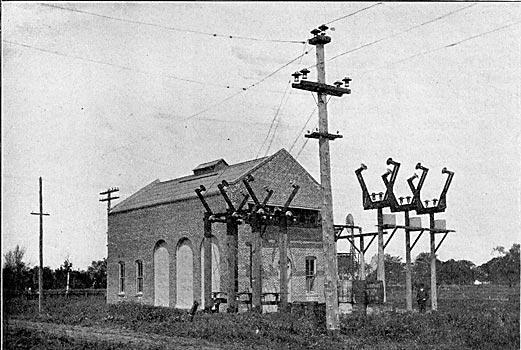
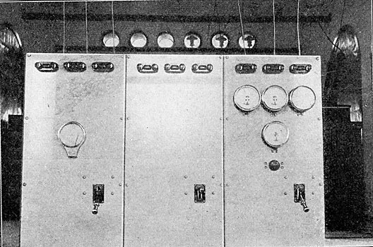
At the Stockton terminus of the 80-mile, high tension transmission is the neat brick sub-station shown in Fig. 15. This view also illustrates the high-tension switching apparatus and lightning arresters, which are of the same types as those shown at the power house. The sub-station is equipped with step-down transformers and as a rule does not require an attendant. There are installed in the station three 150-kw. and three 300-kw., oil-insulated, water-cooled transformers. These transformers are constructed, with taps for 30,000 to 60,000 volts on the primary and 2200 volts on the secondary, with an allowable variation of 5 per cent above or below. The switchboard, Fig. 20, has three panelsone for the transformer and two for the secondary feeders, equipped with oil switches, lightning arresters, instruments, etc.
| |||
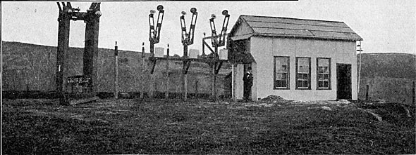
| Fig. 16. Jenny Lind Sub-Station. |
| |||
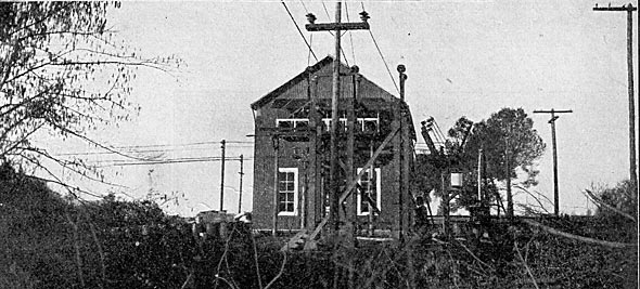
| Fig. 17. High-Tension End of Sub-Station. |
In Stockton the company supplies a commercial service of about 6000 incandescent lights and about 300-horse-power in motors. It has only been operating since early in 1904, and is competing with an old-established company. In the business district of the city the company is placing its commercial three-wire, 220-volt secondaries underground in Edison tubing.
| |||
| Fig. 18. Burned Pole Top. |
| |||
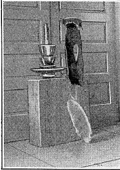
| Fig. 19. Protected Telephone in Stockton Sub-Station. |
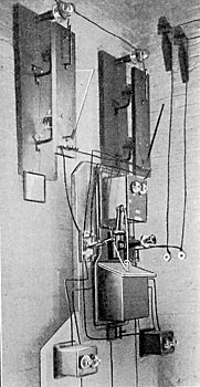
A feature of the sub-station, as well as of the power-house, is the precaution taken in installing the telephone instruments. In Fig. 19 is shown the apparatus in the. Stockton station. The telephone is mounted on the upright portion of a platform which is insulated from the concrete floor by glass insulators. A person talking has to stand on this platform in order to reach the instrument. The two line wires terminate above the telephone, as shown, in special fuses mounted on slate panels that are in turn insulated from the wall. A knife switch with a long break is placed above each fuse so that the line .can be cut out when the fuse is replaced. The telephone line from the power house passes through this sub-station and then to the company's office in the city and the wiring is arranged so that the talking circuit may be cut out when no one is at the station. Knife switches are provided for cutting the talking circuit in and for cutting out either the power house or the office end of the 1ine. No trouble is had in talking over the 80-mile circuit to the power house or over the entire Ho miles to Folsom. In the power house a special concrete booth has been built for the telephone and the latter is also insulated in the same manner as at the Stockton sub-station.
| |||
| Fig. 20. Switchboard in Stockton Sub-Station. |
At various points along the Stockton transmission line the company has been able to develop a good business in the supplying of power. This line runs through some of the richest mining camps in the Mother Lode and the outlook for further development is very good. An electric railway is to be built from Ione to Jackson and Sutter Creek and the American River Electric Company has the contract for supplying the necessary power.
| |||
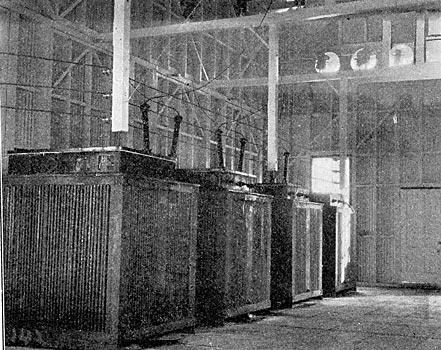
| Fig. 21. Interior of Folsom Sub-Station. |
A spur of the line runs to the Jenny Lind mining section, where the sub-station shown in Fig. 16 has been erected to take care of the business. The equipment consists of three 100-kw. transformers which reduce the voltage to 2200 or 4400 volts, the latter being used. The power supplied from this station is utilized for the operation of gold dredging plants. At Nashville a similar sub-station has been installed, the power in that case being used for quartz mining.
The Folsom sub-station, at which the 30-mile, high-tension line terminates, is constructed of corrugated iron and covered with P. & B. roofing. The interior of the sub-station is shown in Fig. 21. The equipment consists of four (one spare) 300-kw. transformers stepping-down from 30,000 to 2,200 or 4,400 volts and three 100-kw. transformers stepping-down to 11,000 volts. The entire output of this station is sold to the Folsom Development Company, a corporation which has entered extensively and systematically into the gold dredging business in that vicinity. This company has purchased 18,000 acres of land in that section; has two dredges in operation near Folsom; is operating two or three at a point four miles below, and is planning to build ten or a dozen more in the near future. As this phase of electric power development is an interesting one, some mention will be paid to it.
| |||
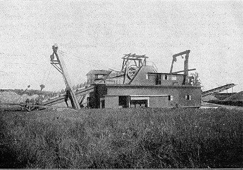
| Fig. 22. Dredge No. 1 of the Folsom Development Company. |
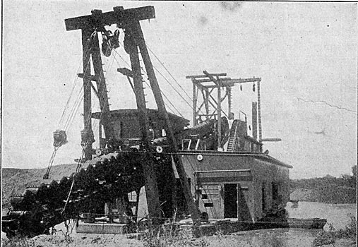
In Figs. 22 and 23 are shown two of the Folsom Development Company's dredgers at work. These dredgers are built on the spot, a pit being excavated for the purpose, and if the land is not near enough to the river to give water to float the boat, water is pumped into the pit. The gold-bearing soil is a gravel deposit that has been washed down in old river channels from the rich Mother Lode district farther up on the mountains. It has only been since electric power could be obtained at a cheap rate that it has been profitable to work this ground, but judging from the investments that are being made now by this and other companies in the way of expensive machinery installations, the business must be a decidedly profitable one. The mining has been reduced almost to a science so that there is little if any chance in the work. The entire land is surveyed and divided into plots so ft. square and in the center of each plot a prospect is drilled by sinking a 6-in. shaft to hard pan. All the gravel and sand that is removed is carefully measured and its gold-bearing properties determined. If it is found that the percentage of gold is high enough to make dredging profitable the plot is reserved for working. Then, as mentioned before, a large pit is dug and the dredger built complete on the spot. Both dredgers illustrated in Figs. 22 and 23 are of the type constructed by the Bucyrus Co., of Milwaukee, but the engineers of the Folsom. Development Company, who have been working on the problem for several years, have designed a dredge which is said to suit the local conditions better and hereafter the company will build all this machinery in its own shops and construct the dredgers complete. The gold-bearing strata varies from 10 to 50 ft. in depth and the boats are designed to work to those depths. The earth is picked up by chain buckets, each bucket having a capacity of 5 cu. ft. The dredgers are generally rated by the capacity of the buckets, and a 5-ft. bucket dredger will dig from 50,000 to 75,000 cu. yds. of material per month. The earth is raised by the buckets and deposited in .a shaker or screening device which shakes the rocks loose from the dirt and small gravel. The rocks are deposited on an endless conveyor belt which delivers them at some distance behind the dredger on ground that has been worked. The soil is washed through shakers and riffles, the gold being deposited on saving tables, while the sand is forced out at the rear through a pipe by means of a centrifugal pump.
| |||
| Fig. 23. Dredge No. 2 of the Folsom Development Company. |
In dredger No. 2 of the Folsom Co., illustrated in Fig. 23, a 100-h.p., variable-speed, induction motor is used to drive by means of a large belt the digging buckets and the drum for raising and lowering the buckets. A 50-h.p., 2200-volt motor is direct connected to the shafts of two Goth centrifugal pumps which are used for pumping water onto the riffles and shakers for washing the earth. On the deck of the dredger is a 30-h.p., 440-volt motor which drives the shaker and also operates the large rubber rock conveyor belt that is seen extending in the rear of the boat. A 20-h.p., 440-volt, variable-speed motor is used for driving the winches with which the boat is moved from one position to another and which are also used for raising the spuds.
There are two of these spuds at the rear corners of the boat and they are used to hold the dredger in position while it is operating. One spud is built of steel 50 ft. long and weighs about eighteen tons, and the other is of wood and weighs about ten tons. A 30-h.p., 440-volt motor is connected to a centrifugal pump which is used to force the sand discharged from the screws through the pipe on the conveyor ladder. There is a 3-h.p. motor that drives a centrifugal pump used in priming the large pump used for washing the decks and similar purposes. This equipment of six motors, aggregating 233 horsepower, is controlled and operated from a controller or switch room located at one corner of the upper deck. The buckets and winches are operated from this room by means of levers and a specially wound controller. A lighting switchboard located there controls the 125 16 c.p. incandescent lights that are used to illuminate the boat and surroundings at nigh t, as the dredging work is carried on night and day. Five-lamp clusters are used with reflectors for the exterior lighting. Arc lamps of ordinary construction cannot be used on the dredgers on account of the constant vibration of the boat.
The present accepted construction of the dredgers call for the location of the transformers on the boat, but on account of the insurance regulations a special sheet-iron-lined compartment is built on the outside of the boat to contain them. The transformer room on No. 2 dredger contains three 30-kw. Westinghouse transformers which reduce the voltage from 2200 to 440 volts. All the motors on this boat are of General Electric manufacture. Dredge No. 1, illustrated in Fig. 22 has equipment similar to that of No. 2, with the addition of a 10-h.p. motor driving a centrifugal pump for discharging water into the hopper into which the buckets empty.
A very important feature of the electrical operation of the dredgers is the cable which is used to transmit the power from the end of the pole line to the bank of transformers on the boat. After a good deal of experimenting with various kinds, the electrical department of the company has adopted a standard cable which consists of three No. 2 double rubber-covered 3/32-in. insulation wires pulled into a 1-1/4-in. heavy rubber hose. The joints of the hose are carefully cemented and the cable is then tested to 10,000 volts. This cable has proved very satisfactory, and although generally supported above the water by barrels it can be safely used under water. The extent to which the Folsom Development Company is carrying on its dredging work has war ranted it in erecting a large machine shop, offices, etc., on the ground, a general view of which is shown in Fig. 14-D. At these shops everything in the way of machine work for new dredgers as well as repairs on those in operation is being carried on, the foundry work being done in Sacramento. The machine shop is well equipped with heavy tools and is operated electrically, seven motors ranging from 3 to 3o horsepower being used for the purpose. A portion of the shop is also fitted up for electrical repair work. All the electrical work of the company, including that on the dredgers and in the shops, is in direct charge of Mr. A. B. Coon, electrical engineer of the company.
| |||
| Fig. 24. Portable Sub-Station at Folsom. |
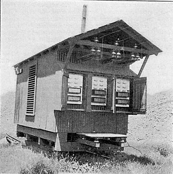
An allied corporation has in operation near Folsom a dredge in connection with which is used the unique portable sub-station illustrated in Fig. 24. This transformer house is mounted on a street-car truck and is moved around on a temporary track as frequently as is necessary. The building contains three 50-kw. Westinghouse transformers delta connected. They reduce the voltage from 11,000 to 1200 volts. The high-tension fuses and a set of Westinghouse low-equivalent lightning arresters can be seen in the opened compartments at the end of the station. The current is carried from this sub-station to the dredger at 1200 volts in a flexible water-proof cable which contains three conductors. The dredge is a typical New Zealand gold electrically operated. The boat was built by the Risdon Iron Works, of San Francisco, and placed in operation about two years ago. The largest motor on the boat is a 75-h.p. type F Westinghouse variable?speed induction motor which drives the digging buckets. The pump which supplies the water for washing the gravel is driven by a 50-h.p. Westinghouse type C constant?speed motor. These two motors are operated at 1200 volts. The smaller motors on the boat are one 20-h.p., constant-speed machine driving the conveyor, two variable-speed motors operating the two Winches and one 1-h.p. motor driving a small pump for 440 volts. A bank of three 25-kw. Westinghouse type O. D. transformers are used on the boat for reducing the voltage from 1200 to 440 volts and also to 110 volts for lighting purposes. About 75 incandescents are employed for lighting on the boat. The capacity of the buckets on this dredge is five cu. ft. each and about fourteen buckets are dumped per minute. This boat has been in almost constant operation since being placed in commission two years ago.
The Folsom Company has in connection with its plant a portable compressor plant, consisting of a 10-h.p., 440-volt motor belted to a compressor. This outfit is enclosed and mounted on a wagon so that it can be readily hauled to any desired spot and used for drilling, repair work, etc.
In addition to the extensive field for power furnished by the gold dredging and mining companies, the American River Electric Company expects to develop a good business in irrigation pumping. Its lines tap a rich agricultural section where water can be easily obtained at a depth of about twenty feet, and with cheap electric power there is every reason to expect that the development along this line will be profitable to the company as well as the farmer.
Credit for the design and erection of the American River Electric Company's plant is due to Mr. A. M. Hunt, of San Francisco, recently of the Engineering Offices and also recent general manager of the Independent Electric Light & Power Company of that city. The original features of the system that have been mentioned are practically of Mr. Hunt's design. The entire plant was erected and put in successful operation in about six months, which is an exceptionally short time when the engineering and practical difficulties are considered. Mr. Hunt received very valuable assistance from Mr. B. C. Condit who had active charge of the construction or the plant and is now directing the further operation and development of the system, through his position as superintendent of the American River Electric Company. Appreciation is due both of these gentlemen, as well as to Mr. Mortimer Fleishhacker, of San Francisco, the president of the company, for their courtesy and kindness in assisting the writer in the preparation of the foregoing description.
