[Trade Journal]
Publication: Electrical Age
New York, NY, United States
vol. 34, no. 1, p. 38-48, col. 1-3
Three-Phase 40,000-Volt Power Transmission
From Gromo to Nembro, Italy
By L. RAMAKERS
THE Serio, a swift-flowing mountain stream having its origin in the Alps, north of the industrial town of Bergamo, in Lombardia, Italy, was found to be capable of developing 4000 H. P. Of this amount, 2000 H. P. were available at Gromo, and the remaining 2000 H. P. at a point higher up the stream. At present this river has been utilized only at Gromo.
The problem which had to be solved by the engineers was as follows:Given 2000 H. P. at Gromo, to convert this into electrical energy and transmit it by means of one or two three-phase overhead lines to Nembro, a small town about 21 miles distant, for the purpose of operating spinning mills. For a time but one three-phase line shall be needed, although a possibility exists that a second line will afterward be installed for carrying the energy to a greater distance. Provision must therefore be made for ultimately supporting this second line on the same poles used for the first line. It is important that the loss in the line be a minimum, although it is equally essential that the prime cost of the installation be kept low. Furthermore, the design of the entire plant must be such as to afford simplicity of operation and insure a safe working of the system.
These were the conditions which had to be fulfilled, and the carrying out of the scheme was entrusted to the well-known firm of Messrs. Brown, Boveri & Co., of Baden, Switzerland.
| |||
| The Generating Plant and Switchboard Gallery |
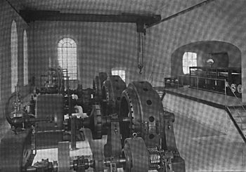
The central station has been built in the valley, a few minutes' walk from the village and at the foot of the mountain on whose face the top part of the penstock was laid. The lower portion of the pipe line, extending up to the power house, has been placed underground.
In the power house three generators of 1000 H. P. each, direct-coupled to Escher-Wyss turbines, were placed in a row. Behind the generating sets two exciters, also directly driven by water wheels, and each having a capacity of 25 K. W., have been put down. The third generating set has been provided as a reserve in case of a breakdown.
Each generator is connected directly to the primary of a step-up transformer; that is, without any instruments intervening. The current leaves the secondary terminals of the transformer at a pressure of 40,000 volts, and is then led to the high-pressure bus-bars, in order to permit of parallel operation with the other units. The switches necessary for effecting parallel operation are thus situated in the 40,000-volt transformer circuit. The turbine, generator and transformer really form one unit.
By eliminating the bus-bars between generators and transformers, the number of controlling and measuring devices is practically halved. The current and pressure transformers for the ammeters, voltmeters and the overload relays of the automatic switches are energized from the low-pressure circuit: that is, from the 4000-volt side. Since the ratio in each of the transformers is 1 to 10, it follows that the ammeters and voltmeters indicate simultaneously the current, pressure and phase difference of both the 4000-volt and the 40,000-volt circuits.
| |||
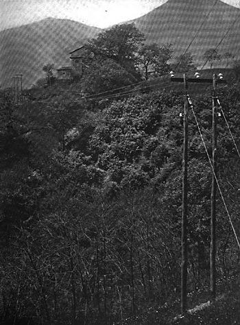
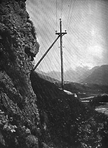
| A Portion of the Transmission Line |
The generators are of the standard horizontal shaft type with stationary star-connected armatures and revolving-field magnets. Each machine has a rated capacity of 1000 H. P. at the pressure of 4000 volts, and a power factor of 0.08. Each of the machines has 12 poles and runs at a speed of 500 revolutions per minute, which corresponds to a frequency of 50 cycles per second. The guaranteed efficiency, including excitation losses, 93 per cent. at full load and 89.5 per cent. at half load. The drop of voltage from no load to full load was found to be 7 per cent. on a power factor of unity, and 20 per cent. on a power factor of 0.80. The magnet-wheel, poles and pole shoes form one steel casting.
Each exciter is capable of developing 25 K. W., 217 amperes at 115 volts, when running at a speed of 800 revolutions per minute. Each of these dynamos has 6 poles, which are built up of soft-iron laminations. The dynamo frames are constructed of the best cast-steel. The armatures are each of the slotted drum type. The guaranteed efficiency for each of these sets was 89 per cent. at full load and 87.5 per cent. at half load.
| |||
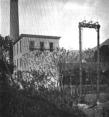
| The Sub-Station at Nembro |
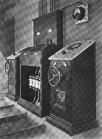
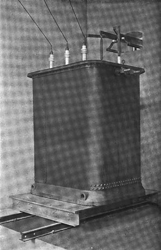
Each transformer is designed to give an output of 850 kilovolt-amperes when working on a 50-cycle circuit. The ratio of transformation, as already mentioned, is 4000 to 40,000, or 1 to 10. The efficiency obtained on a non-inductive load was 97.8 per cent., 97 per cent. being the guaranteed figure. The inherent regulation, that is, the drop of voltage from no load to full load, on a non-inductive load was 0.76 per cent., and with a power factor of 0.7 it was 2.6 per cent. These transformers withstood a flash test of 67,000 volts applied between primary and secondary windings. The over-all dimensions of each of the transformers are as follows:length, 63 inches: breadth, 53 1/2 inches; height, 85 13-16 inches.
The transformers are of the oil-insulated and water-cooled type. Each transformer consists of three vertical limbs placed in the same plane, and held firmly together at both extremities by means of soft-iron yokes. The primary and secondary windings are wound in the shape of concentric cylinders, and are separated from each other by means of a strong insulating partition. To remove as far as possible the danger of a breakdown, the high-pressure coil is wound in sections. Each subdivision has a potential difference of only 300 volts between its terminals.
| |||
| The Switch Gear in the Sub-Station |
The switch gear, which is of the utmost importance in installations such as the one here considered, is erected. together with the transformers, in a special building adjoining the generator room. This building consists of a basement and three stories, each of the latter having a floor space of 754 square feet. The basement is divided into two compartments, one of which is situated 3 feet 9 inches below the generator room floor level, and contains the regulating resistances and framework for the 4000-volt apparatus, while the other compartment is situated 8 feet 10 inches above the generator room floor and holds the transformers. The leads from the generator room reach the first compartment through a wide trench under the generator room floor.
The first floor is also divided into two rooms, one of which gives access to the generator room, forming a kind of gallery from which the whole installation may be overlooked. This compartment contains the main operating board, on which are mounted the switch hand wheels and measuring instruments. In the second room are located the high-pressure automatic switches and the three current transformers for the outgoing feeder.
The 4000-volt conductors, the exciting leads for the generators and the exciter leads themselves are all placed in one common trench under the generator room floor, leading into the basement. The second floor is entirely taken up by the bus-bars, and by the pressure transformers connected with them. The third floor has been reserved for the lightning arresters and the leading-out arrangements of the line.
| |||
| Another View Along the Transmission Line |
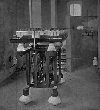
Each generator is provided with a framework, on which are mounted three high-pressure single-pole removable tube type fuses with blow-out horn, one pressure transformer with fuses, and two current transformers. The framework is a riveted structure made completely of iron, the sides being covered with embossed sheeting. At the front, removable shields have been provided in order to permit renewal of the fuses, or their inspection when necessary. The leads enter the transformer room through thick glass tubes cemented into the dividing wall.
In laying out the 40,000-volt apparatus, the extra high-pressure bus-bars were taken as the starting point. In order to exclude all possibility of arcs being formed between bars of different polarities, each phase was enclosed in a separate cell made of en�combustible material. Each insulator consists of three parts, glazed separately and baked together; on the main body of the insulator are four deep grooves.
| |||
| One of the 500-K. W. Transformers |
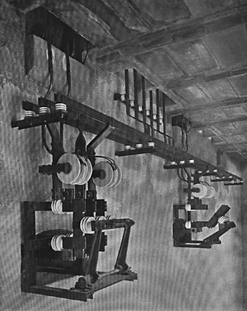
Immediately below the high-pressure bus-bars on the first floor, the high-pressure oil switches are located. To avoid the use of heavy apparatus, each phase has been equipped with a separate switch. The three switches are. however, operated simultaneously. A similar structure was adopted for carrying the switches as for the bus-bars, and each switch is separated from its neighbor by a wall 41 inches in thickness. The brackets and supports for the switches are cemented into the wall. In this way each switch is in a fireproof cell 23 3/4 inches wide. Through an aperture at the top the connections pass from the switches to the bus-bars. Removable disconnectors have also been provided; these permit one to isolate any of the cells when they have to be switched out of circuit to be cleaned or inspected. The disconnectors are composed of copper strips with stop split-pins. These strips fit into two contacts mounted on porcelain insulators, and are handled by means of a wooden rod provided with an insulator at its extremity. To further safeguard the attendant, the bush by means of which the insulator is fastened on the stick, is earthed through a little metal chain; this enables the attendant to operate the disconnectors, when the switches arc open, without running any personal risk.
The switch is operated from a distance by means of the hand-wheel on the main board, and is actuated by a rotary motion, which is probably the most suitable mechanical movement for appliances of this kind, a great advantage being that one is not tied down to a particular spot in operating the switch, for, by means of a countershaft, the apparatus can be controlled at almost any distance.
The switches are of the multiple-break type. Both the moving and stationary contacts, as well as the mechanism, are immersed in an oil bath. All current-carrying parts have been solidly constructed and are of ample cross section. To avoid fusing of the main contacts, small auxiliary Contacts have been provided, which latter carry the current at the moment of breaking the circuit. To make sure that the arc produced when breaking the circuit is quickly destroyed, the contacts have been formed in such a way that, at the moment of rupture, a volume of oil is forcibly thrown against them. In order to weaken the destructive effect of the arc, the circuit is simultaneously broken in six places.
| |||
| The Low-Pressure Bus Bars and Disconnecting Gear |
By this method the moving contacts need travel but a short distance. On turning the switch hand-wheel, the rotary movement is transmitted to the switch spindle, and this, in turn, actuates a crank. The latter moves the contacts and thus closes the circuit, at the same time applying tension to the springs fixed around the guides.
If the switch is operated by hand, and by mistake the crank is turned past the dead point, the switch will, nevertheless, remain closed. When the switch is worked automatically, however, the crank never quite reaches the dead point, but is kept in position by means of a pawl and a cam-wheel. As soon as the pawl is lifted the springs of the switch pull the contacts apart.
In order to refreshen the memory of the attendant, an inscription "wheel to be turned back" appears as soon as the switch is closed. Should the operator, in spite of this reminder, still forget to return the hand-wheel to its off position, even then no harm will result, as it has been proved by tests that the springs of the switch are sufficiently strong to drag the whole driving gear back to its first position. Provision has also been made to open the switch by hand, should the relay fail to act. A knob passing through the center of the switch hand-wheel, when pulled, lifts the pawl on the releasing shaft, and the switch opens in the usual way.
The switchboard is built in the form of a desk, the top part inclining toward the operator; it is placed in the gallery so that the attendant can see the whole of the machinery and at the same time have his hands close to the controlling apparatus. The operating board is equipped only with low-pressure apparatus, and consists of three generator panels, one feeder panel and one exciter panel. It will be of interest to American switchboard manufacturers to learn that no marble or slate was used in the construction. The vertical sides of the boards are covered with ornamental embossed iron sheeting.
| |||
| The Main Operating Board |
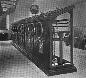
A bus-bar voltmeter is mounted on a bracket placed in a prominent position over the middle of the board. The regulating rheostats, placed directly beneath the operating board, can be inspected without running any personal risk while the station is in operation.
The third floor has been reserved for the lightning arresters, as previously noted, and each phase is separated, from the others by a partition. On a level with the lightning arresters are the leading-out arrangements for the high-pressure line. Each line wire leaves the power house through one of the glass panes of the window. On both sides of this glass pane a stout glass tube projects, through which the conductor passes. This tube is kept in place by two copper hoods soldered to the conductor. The tube is of such a length that the shortest path for leakage to a non-insulating body is about to inches.
| |||
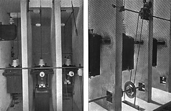
| Front and Rear Views of the 40,000-Volt Oil Switches Used in the Gromo-Nembro, Italy, Electric Transmission Plant. |
The total length of the overhead line is approximately 21 miles. It follows the Serio River till Nembro is reached, where it drives the machinery of large cotton mills. The line has been designed to transmit a total of 4000 H. P. with a maximum drop along the line of 5 per cent. The line consists of three bare copper wires, each 255.905 mils in diameter, and mounted in delta insulators supplied by the Hermsdorf Earthenware Factory.
The insulators are of a new design, specially constructed for this installation. They are supported on wooden poles and cross-arms. As a rule, the Iines are mounted on a single pole in the form of a triangle, each side measuring 33 7-16 inches. The standard height per pole is 26 feet above the ground, and at crossings, 29 1/2 feet. The lower insulators are placed 24 1/2 feet above the ground; at crossings, 27 3/4 feet.
The transformer station is situated at Nembro, in close proximity to the cotton mills. The line enters the building at a pressure of 38,000 volts, this being the voltage to which the generating plant at Gromo has to be regulated. The Nembro station thus far contains only two 500-K. W. transformers of the same type and design as those at Gromo. Space has been reserved, however, for a third transformer. These transformers have been designed for a normal continuous output of 500 K. W. The ratio of transformation is 38,000 to 500.
| |||
| The Lightning Arresters |
The connections of this sub-station, so far as the high-pressure circuits are concerned, are similar to those at the Gromo station. A three-pole emergency switch, mounted on poles outside the station, enables a complete isolation of the sub-station to be effected if necessary. As this apparatus is placed in the open, the possibility exists that, when the sub-station is switched out, discharge of current might result between the live line and the line entering the transformer station. This could happen through the presence between the horns of a foreign body, such as a bird, or it might occur in very rainy weather on account of moisture. To avoid such an occurrence, three contacts have been attached to the switch, and these, when the switch is opened, short circuit the lines entering the station and connect them to earth.
The line enters the sub-station in identically the same way as it leaves the primary station at Gromo, and the current passes through the lightning arresters to the high-pressure bus-bars. The leads from the bus-bars pass through three single-pole disconnectors, and three single-pole automatic high-pressure oil switches, to the primary side of the transformers. The secondary side of the transformers is also provided with three-pole disconnectors and two current transformers; of the latter, one is for feeding the overload relay and the ammeter, while the other is for the relay alone.
| |||
| The Regulating Rheostats |
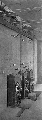
The sub-station is a plain two-story building. Each floor is divided into two compartments. On the ground floor at the rear the transformers are situated; in the front room, mounted on the separating wall, are the secondary bus-bars with the disconnecting gear and current transformers. Immediately above the transformers on the second floor are the high-pressure automatic switches. On the second floor have also been placed the 38,000-volt bus-bars. These are duplicates of those erected at Gromo. The lightning arresters are placed in the next compartment, together with the leading-in arrangements.
This power transmission plant was officially started in July, 1904, and the results obtained were satisfactory beyond expectation; the plant has also withstood the severe thunderstorms which are of frequent occurrence during the hot summer months in the north of Italy.
