[Trade Journal]
Publication: Electrical World and Engineer
New York, NY, United States
vol. 45, no. 3, p. 139-143, col. 1-2
Electrical Power from the Welland Canal - I
DE CEW FALLS have had "greatness thrust upon them." From time to time during several years news items have appeared relative to a great development of water power at De Cew Falls and its electric transmission to Hamilton, Canada, some 35 miles away. As a matter of fact, the falls are quite innocent of all this, and the water for the power development comes from Lake Erie by way of the Welland Canal.
| |||
| Fig 1 - Map of Works, Lines, Etc. |
Beaver Dams Creek is one of the small streams that rise in the high tableland between Lakes Erie and Ontario, and its waters tumble down the escarpment that lies several miles inland from the shore of the latter. Near the brow of this escarpment, at a point about three miles from the small but ancient and interesting city of St. Catharines, the creek is received in a reservoir that has been constructed to supply that city with water. Below this reservoir its overflow follows the old bed of the creek, and in so doing plunges into a deep gorge that the stream has carved out of the escarpment on its way to the lower lake during past ages, much as the Niagara River has done on a far greater scale a few miles to the east. This small overflow from the city reservoir, together with the discharge of a brook that joins the creek a little below the reservoir outlet, is all of the water that passes over De Cew Falls, and in dry summer weather the bed of the stream is bare.
| |||
| Fig 2 - Penstocks, Power House and Transformer House. |
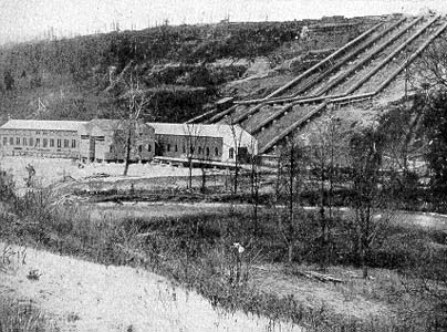
Turning from the mythical water power at De Cew Falls, the real development is found at the foot of the escarpment, on Twelve Mile Creek, a little more than half a mile away. This creek is as free of capacity for power development as the one above named, but its bed is only thirty-odd feet above the surface of Lake Ontario, and thus forms a cheap and convenient tail-race for water from the power house.
| |||
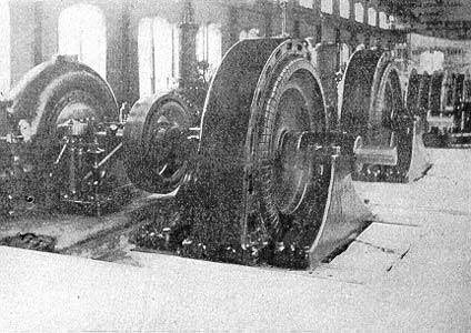
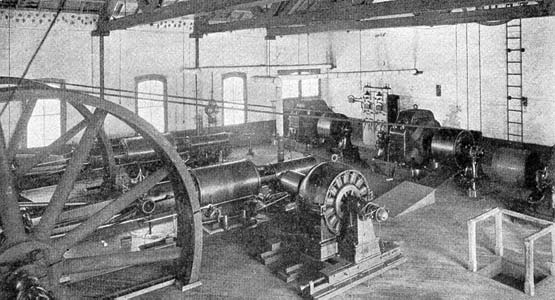
| Fig 3 - Interior of De Cew Falls Power House. |
Water for this power development is drawn from the old and new Welland Canals close to their point of junction near Allan-burg, Township of Thorold, County of Welland, Ont., about four miles distant. All save about Boo ft. of this distance, which represents the approximate length of the steel pipes between the fore-bay and the power house, is traversed by a canal that widens into reservoirs at several points. During the past year the canal and these storage reservoirs have been much enlarged, so that the latter, which formerly had an area of only 40 acres, now measure 450 acres, and contain 50,000,000 cu. ft. of water. Taking the normal surface of Lake Ontario as zero level, the elevation of water in the power canal at the intake weir is about 325 ft., at the forebay the elevation is 306 ft., and the elevation of the tail water in the creek below the power house is 38 ft. Between the surfaces of forebay and tail water the difference of elevation is thus 268 ft., from which a small deduction must be made for loss by friction in the pipes, in order to get the effective head on the wheels. This hydraulic development has been constructed under the right to draw water continuously from the Welland Canal at the rate of 700 cu. ft. per second during a period of 63 years. The storage basins are designed for a rise and fall of 3 ft. in their water level when in use, and the volume of water that may be drawn from them during a period of heavy load is thus 450 X 3 = 1,350 acre-feet, besides the constant diversion of 700 ft. per second from the Welland Canal. As one acre-foot equals 43,560 cu. ft., a reduction of 3 ft. in level over the 450 acres of the reservoirs would yield 5,880,600 cu. ft. of water for the power plant, a volume equal to that which may be drawn from the Welland Canal during 23.33 hours.
| |||
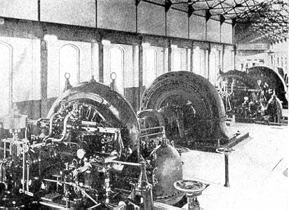
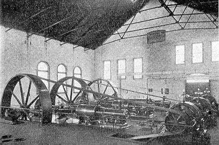
| Fig 4 - Interior of De Cew Falls Power House. |
Allowing 8 ft. of head for the losses in the pipes and draft tubes that connect with the turbine water wheels at the power house, so that the effective head is 260 ft., the 700 cu. ft. of water per second that may be drawn from the Welland Canal, at 62 pounds per cu. ft., will develop 20,516 hp. If the turbines have an efficiency of 80 per cent., the allowable draft on the Welland Canal will thus develop about 16,000 hp for electric generators. This output may be multiplied several times by use of the stored water during short periods of several hours each.
The forebay on the brow of the escarpment, some 250 ft. above the power station, terminates in a heavy masonry wall that is pierced by four steel pipes of 15.5 ft. inside diameter each. Provision is also made for two more of these pipes that will be installed later, and each is provided with a head gate. Somewhat more than halfway down the face of the cliff the direction of the pipes changes, so that they make only small angles with the horizontal for some distance, to correspond with a natural shelf of the escarpment. On reaching the power house the pipes pass underneath the main floor, and to water wheels that are arranged in a row along its more distant side.
| |||
| Fig 5 - Motor-Generator Set and 300-Kw Rotary Converter, Sub-Station "A". |
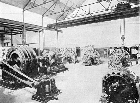
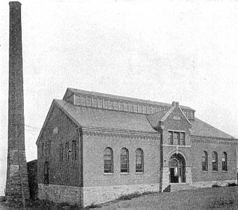
The power house is a long, narrow;-one-story brick building, with its longer sides approximately parallel with Twelve Mile Creek, which serves as the tail-race, and at right angles to the general direction of the steel pipes. Steel trusses support the roof of the station and beneath them a traveling crane sweeps the entire space occupied by the water wheels and electric generators. The wheels and generators are in the same room, each generator is direct-connected to its own wheel, and all of the units thus formed are horizontal and are arranged in a row parallel to the longer sides of the station. At one side of the station is the transformer house, a separate building, where the high-voltage lines that transmit the energy to Hamilton terminate.
Eight main turbine sets are provided for the operation of an equal number of electric generators. Two of these turbines are of the Stilwell-Bierce make, single-runner, single-discharge type, and each is rated at 1,700 hp and 400 r.p.m. Another two wheels are of the A. Riva, Manneret make, single-runner, single-discharge type, and each is rated at 286 r.p.m. and 3,300 hp. Each of the other four main wheels was built by J. M. Vaith, of Heidenheim, Germany, has a double runner and double discharge, and is rated at 7,100 hp and 286 r.p.m. For the operation of exciters there are two Stilwell-Bierce turbines, each rated at 800 r.p.m. and 50 hp. A 30-kw Crocker-Wheeler exciter is direct-connected to each of these turbines. All of the above water wheels operate under the approximate head of 268 ft.
To each of the 1,700-hp wheels a Royal Electric inductor alternator is direct-connected, and each of these alternators is rated at 1,000 kw. A Canadian General Electric alternator of 2,000 kw capacity is coupled to each of the 3,300-hp turbine wheels. The 7,100-hp wheels are intended to drive four alternators of 5,000 kw capacity each, and two of these alternators of the Westinghouse make are vow in position. All of the alternators just named are of the three-phase type, and operate at about 66 cycles per second and 2,400 volts. The combined rating of the six alternators now in position is 11,000 kw, and the other two 5,000-kw generators for which provision has been made will raise this total to 21,000 kw.
| |||
| Fig 6 - Switchboard Gallery. |
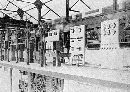
Much the greater part of the electric energy developed at this water power station is raised to 22,500 volts and transmitted to Hamilton, 34 miles away, but a portion of it goes to the city of St. Catharines, about three miles distant, at the generator voltage of 2,400 for electric supply there. In the transformer house at the generating station there are at present 25 transformers for raising the generator voltage of 2,400 to 22,500, or to 45,000 for the transmission. Twenty of these transformers are of Royal Electric make, oil-insulated, water-cooled, and step the voltage from 2,400 to 22,500, three-phase. Ten of these twenty transformers have an individual capacity of 200 kw, and the other ten an individual capacity of 400 kw, so that the combined capacity of the group of twenty is 6,000 kw. Five other transformers, also of the oil-insulated, water-cooled type, are of Westinghouse make, are rated individually at 2,500 kw, and operate from 2,400 volts primary to either 22;500 or 45,000 volts secondary, as desired. For these five transformers the combined rating is 12,500 kw, so that the total capacity of transformers now at the water power station is 18,500 kw. To this there will be added five more transformers, each of 3,300 kw rating, oil-insulated, watercooled, and working with 2,400 volts primary and either 22.500 or 45,000 volts secondary. These last-named transformers will raise the step-up capacity at the generating station to 29,000 kw. Connections between the generators, the transformers and the transmission lines are made through three-pole, electrically-operated, nonautomatic oil switches. Each generator circuit passes through two 1,600-amp. switches of this type, in series. Besides the controlling switches for the power circuits, the switchboard and pedestals carry a full equipment of indicating instruments and recording wattmeters. The oil switches, switchboard and instruments are of Westinghouse make.
| |||
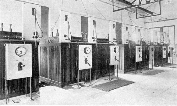
| Fig 7 - 500-Kw Stepdown Transforers, Sub-Station "A". |
Two transmission lines leave the terminal house at the generating station for Hamilton, and each conductor of these lines is connected to a Canadian General Electric air-gap lightning arrester, designed for 22,500 volts, and passes through a choke coil before it reaches. the transformers. One transmission line runs from the water power plant to the sub-stations in Hamilton by way of the low, level strip of land. that lies between the foot of the Niagara escarpment, or "mountain," as it is called, and the shore of Lake Ontario, and the length. of this line is 33 miles. The other transmission line passes from the power station up the face of the escarpment, and then runs along near its brow for nearly the entire distance to Hamilton. By the way of this line the distance between the power house and the substation in Hamilton is 34 miles. The maximum distance in elevation between the two lines is about 300 ft., and their greatest distance apart is about 10.5 miles. Each transmission line consists of a single circuit mounted on porcelain insulators and wooden pins, cross arms and poles.
| |||
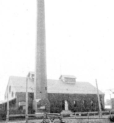
| Fig 8 - Exterior of Beach Station. |
| |||
| Fig 9 - Exterior of Guise Street Station. |
For both circuits the insulator is the same, namely, a two-part, No. 9 S 40,000 type, made of porcelain by R. Thomas & Sons. This insulator has one large petticoat of 9 in. diameter, and a sleeve that runs down 5 in. below this petticoat. At its lower end the sleeve has a diameter of 4.5 in. The total height from the lower edge of the sleeve to the top of the insulator is 8.75 in., and the width of the wire groove at the top of the insulator is 1 in. A special locust pin carries each of these insulators and has a diameter of 1-3/4 in. in the shank that enters the cross arm, and 2 in. at the shoulder just above the cross arm. As the insulator is mounted, the lower edge of its petticoat is 5/8 in., and its top is 9-3/8 in. above the top of the cross arm. The two transmission circuits are arranged quite differently on their poles. The circuit that occupies the low land between the escarpment and the lake, known as No. 1, consists of three stranded aluminum conductors, each having a cross section of about 320,000 c.m. One of these conductors is mounted at the tops of the poles, and the other two are at the ends of a single cross arm, so that the three conductors are at the corners of an equilateral triangle with sides of 45 in. each. For No. 2 circuit, which runs along the top of the escarpment, six copper conductors are employed, three solid and three stranded, and each of these conductors is No. oo. These six conductors are arranged in pairs on three two-pin cross arms, so that there is a distance of 54 in. between each pair and the one nearest to it. Each pair of wires on one of the two-pin cross arms forms one conductor of the three-phase circuit. Before the aluminum conductors were erected the six copper wires that now form one circuit were run three on each pole line, and then served as two independent circuits. In the past the voltage of transmission has been 22,500, but it is the intention to raise it to 45,000 in the near future.
| |||
| Fig 10 - Interior of Beach Station. |
Energy brought by these transmission lines is delivered in Hamilton at two sub-stations, known as "A" and "B," respectively, and also at two smaller sub-stations in the towns of Grimsby and Beamsville. Sub-station "A" is located on Victoria Avenue North and is distant about 1-1/4 miles from the City Hall and business center of Hamilton. This sub-station is also on the line of the Grand Trunk Railway, so that its coal supplies are received directly from the cars. In structure the sub-station is a brick building with concrete floor and steel truss roof, and is one story in height. Some changes are now going on in the equipment of this sub-station and when these are completed the apparatus there will be as stated below. On entering the building both of the transmission circuits are provided with choke coils and General Electric air-gap lightning arresters before going to the transformers. The 20,000 or 40,000-volt, three-phase current from the water power plant is received at sub-station "A" by 23 transformers that lower the pressure to 2,400 volts, two-phase. Fifteen of these transformers are of Westinghouse make, 20,000 or 40,000 volts primary and 2,400 volts secondary, and each of these is rated at 500 kw, so that their combined rating reaches 7,500 kw.
The remaining eight step-down transformers at this sub-station are of the Royal Electric make, 20,000 volts primary and 2,400 volts secondary, and rated at 175 kw each, so that their combined rating amounts to 1,400 kw. For the entire number of 23 step-down transformers the combined rating is thus 8,900 kw. All of these transformers are oil-insulated and self-cooling. Each of the 500-kw Westinghouse transformers is of rectangular shape and at one of its sides there is mounted a marble panel with ammeter and a four-pole, oil-break switch for the 2,400-volt winding. The high-tension, three-phase circuits are run some feet above these transformers on line insulators that are supported by cross arms beneath the roof trusses. The primary windings of each of these transformers are connected to the transmission circuit through long-break air switches mounted above it, but not intended to open under load. From the foregoing step-down transformers a part of the 2,400-volt, two-phase, 66-cycle current goes to four Canadian General Electric, constant-current transformers rated at 8,000 volts and 7 amp. each on the secondary side. These transformers operate about 450 series enclosed arc lamps on the city streets. A motor-generator for the operation of direct-current elevator motors about the city is made up of a two-phase, 2,400-volt, Royal Electric synchronous motor of 240 kw rating direct-connected to a 200-kw, 500-volt generator made by the Canadian General Electric Company. From this, motor-generator current at 250 volts is supplied to elevator motors by means of a balancing set and a third wire. Current for street car motors is developed at this sub-station by three rotary converters of Westinghouse make, each of which is rated at 300 kw, 600 volts, 66-2/3 cycles and 667 revolutions, two-phase. These converters draw their energy from transformers whose primary windings are connected to the 2,400-volt bus-bars. With these converters there is connected a storage battery of 255 cells that have a discharge capacity of 400 amp.-hours.
Besides the above transforming and converting apparatus, substation "A" contains two steam-driven generators that are held in reserve for use in case of a failure in the water power or transmission system. Each of these generators is rated at 1,000 kw, 2,400 volts, 66 cycles, two-phase, was made by the Westinghouse Company and is direct-mounted on the shaft of a 28 by 54 by 42-in. Goldie & McCulloch cross-compound engine, that operates at 100 r.p.m. and is non-condensing. Steam for these two engines is generated at 165 pounds gauge by four Sterling water-tube boilers of 500 hp each. With these boilers there is a steam-driven equipment for induced draft built by the Buffalo Forge Company. For the 2,400-volt, two-phase, the series arc, the 500-volt, direct-current and the 600-volt railway circuits that leave sub-station "A" there are switchboards with the usual equipments.
| |||
| Fig 11 - Interior of Guise Street Station. |
Sub-station "B" contains only transformers with the necessary switches and instruments. This sub-station is designed for an ultimate capacity of 12,000 kw in 24 tranformers rated at 500 kw each, but the present equipment is limited to 12 of these transformers with a combined rating of 6,000 kw. These 12 transformers are of Westinghouse make, oil-insulated, self-cooling and operate from either 20,000 a 40,000 volts primary, three-phase to 2,400 volts secondary, two-phase. With the 8,900 kw of transformer capacity at substation "A" and the 6,000 kw at sub-station "B," the total rating of the step-down transformers in Hamilton reaches 14,900 kw. Substation "B" is located at Irondale, a suburban section of Hamilton,' on Burlington Bay, and about three miles from the city hall. Within a mile of this sub-station is the great plant of the International Harvester Company and several of the other factories that are operated by the transmitted current. Sub-station "B" is a one-story brick building with concrete floor and basement.
On their way from the water power plant to Hamilton the transmission lines connect with small sub-stations in Grimsby and Beamsville. At the former place the step-down equipment consists of two 150-kw transformers, cooled by air blast, that operate between 20,000 volts, three-phase and 2,400 volts, two-phase. Connected with these transformers is a 300-hp, 2,400-volt, two-phase induction motor, direct-coupled to a 250-kw, 600-volt Canadian General Electric generator that supplies current for the Hamilton, Grimsby & Beamsville Electric Railway. In the sub-station at Beamsville are two 25-kw, 20,000 to 2,400-volt transformers for the supply of lighting service in that town.
 |
| Fig 12: Insulator Hamilton Transmission Line. |
Besides the sub-stations "A" and "B" in Hamilton, there is a steam power station at Guise Street, on Burlington Bay, that contains three generators rated at 250 kw and 600 volts each, for the street railway. Another street railway steam station is located at Hamilton Beach and contains direct-current generators of 500 kw combined capacity. Both of these steam power stations are now out of regular use and are held in reserve as security against any failure of the transmission system.
Current for the electric railway in Hamilton, the line to Hamilton Beach and the Hamilton & Dundas Railway is now supplied by the three converters of 500 kw combined capacity in sub-station "A." Electric supply at Hamilton Beach and in Burlington is delivered by 2,400-volt lines from sub-station "B" and lines of equal voltage from sub-station "A" furnish light and power in the town of Dundas.
