[Trade Journal]
Publication: Electrical Review
New York, NY, United States
vol. 46, no. 16, p. 670, col. 1-3
Westinghouse Choke Coils.
Lightning arresters are employed to relieve the line of abnormal rises of potential due chiefly to static disturbances, while it is the function of choke coils to prevent such disturbances from entering the apparatus which they protect. The choke coil operates on the principle that a coiled conductor presents a greater resistance to the passage of an electric current of high frequency than to one of relatively low frequency; therefore, though a coil may have a very slight resistance to direct current or to alternating current of from 3,000 to 7,200 alternations, its resistance to lightning discharges or other static disturbances, which always occur very suddenly, may be very great.
In order that the choke coil may perform its duty successfully, very great care must be exercised both in its construction and in its installation. The Westinghouse Electric and Manufacturing Company has for the past twelve years been engaged in the manufacture of choke coils and the development of protective appliances for circuits of both high and low potential.
 |
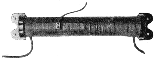
| Fig. 1. — Low-Voltage Choke Coil for Railway Work. |
For low voltage circuits, such as railway work, the form illustrated in Fig. 1 has been developed. The conductor is coiled in the form of a cylinder and is mounted on a wooden spool, each turn being insulated from its neighbor and the completed coil skillfully protected from moisture and dampness. The lightning arrester is connected to a terminal plate laid across a few turns of the line end to provide a selective path to earth.
 |
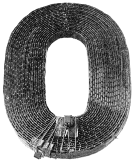
| Fig. 2. — Disc Form of Choke Coil for Alternating Currents. |
In alternating-current work, a disc form of coil has been found to give the best protection. A form of this coil is shown in Fig. 2. The insulation of these disc-form choke coils, which are known as the Westinghouse type 7, has great dielectric strength and extends beyond the sides of the conductor, so that there is little likelihood of the discharge jumping from terminal to terminal or from layer to layer. The coils are constructed with a large factor of safety. Very large cooling surfaces are provided. As the coils are wound with but one turn per layer, every turn is exposed on two sides and offers a maximum radiating surface to the cooling influence of the surrounding air.
 |
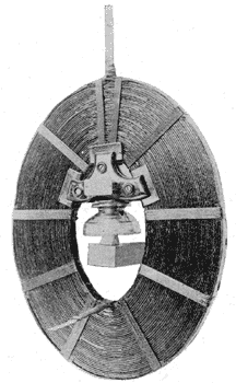
| Fig. 3. — Alternating-Current Choke Coil Mounted on Insulator. |
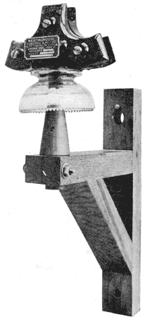
As these coils are connected in the line, it is desirable to mount them on insulators capable of withstanding the line voltage. The coils much also be held securely against the side pull due to magnetic action. To meet these conditions the support illustrated in Fig. 4 has been developed. It is very strong and the insulator which accompanies it has given excellent service at the voltages for which choke coils of this type are designed.
 |
| Fig. 4. — Insulator and Support for Alternating-Current Choke Coil. |
Coils of this type vary in the size of the conductor and in the number of turns, depending upon the current and voltage of the apparatus which they are intended to protect. They are manufactured in a great many different capacities, ranging from 7 to 200 amperes and from 2,500 to 25,000 volts, inclusive. Coils of the same type have been successfully used for the protection of apparatus with a potential lower than 2,500 volts, where the conditions are such as to require protective devices of this form.
For apparatus with potentials higher than 25,000 volts, two forms of choke coils have been developed, viz., the oil-immersed choke coil and the static interrupter. Oil immersion improves the insulation, while the addition of a condesner such as is used in the static interrupter makes it possible to reduce the relative size of the coil, at the same time providing increased protection. Either of these devices can be made to afford effective protection against powerful disturbances. Both are immersed in oil and can be either of the self-cooling or water-cooled type. The oil-immersed choke coil is mounted on a wooden frame and is ventilated in such a way as to maintain a temperature uniform in every part. The ventilating ducts when filled with oil add
·
·
[Missing text]
·
·
