[Trade Journal]
Publication: Engineering (London)
London, England
p. 568-570, col. 1-2
HIGH-TENSION INSULATORS.
By E. H. CRAPPER, M.I.E.E.
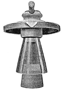
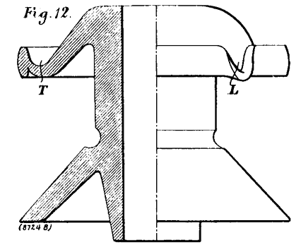
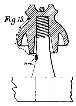
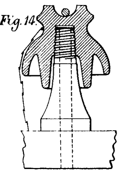
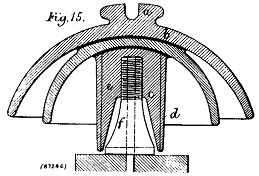
AN ideal insulator is obviously one that is designed and proportioned so that it should give way or break down both by surface arcing and by puncture under a certain sufficiently high voltage; but as the weather conditions are so variable, it is more usual to design the insulator so that the voltage required to puncture the insulator exceeds that which is necessary to produce arcing from the conductor to the pin. One method of increasing the arcing distance is represented by the Locke high-tension insulator, shown in Fig. 11, which is of the mushroom type, and is made of brown china-ware, with a glass or porcelain cone surrounding the wooden pin, which is further protected by an additional porcelain sleeve and base. The upper portion is in the form of a bevelled trough to catch the rain, a lip being also introduced to carry off the water on one side of the cross-arm. The principle of the trough T and the lip L is very clearly indicated in the type of insulator shown in Fig. 12. The function of the sleeve introduced in the Locke high-tension insulator is additional protection against static discharges or arcing from the conductor or insulator to the wooden supports, which may result in the destruction of the support by burning it off, as indicated in Fig. 13. Fig. 14 shows the protecting sleeve extending over the inner portion, thus increasing the arcing distance even under the severest strains, and adding from 5000 to 30,000 volts to the capacity of the insulator. The details of the construction are given in Fig. 15, in which the sleeve c may be single fitting, or it may be made to consist of two parts, d and e, which are dried, like the bells a and b, glazed, and fused to them.
 |
| Fig. 11. |
 |
| Fig. 12. |
 |
| Fig. 13. |
 |
| Fig. 14. |
 |
| Fig. 15. |
Experience proves that resistance to puncture may be secured in a high degree by making the insulator of several separate and distinct bell-pieces and introducing one piece within the others. In this way the composite or glazed-filled multi-part porcelain insulator is constructed, the different pieces being nested and cemented together during b the process of manufacture by layers of glaze.
 |
| Fig. 16. |
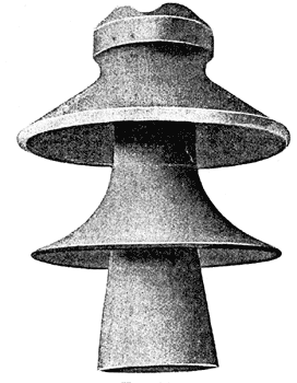
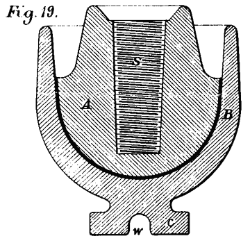
A good example of the modern multi-part porcelain insulator for high tensions and large dimensions is the glaze-filled high-tension insulator made by the R. Thomas and Sons Company, Ohio (United States), and shown in Fig. 16. It is made of brown glaze porcelain—the best English china clay only being used — and is glaze filled. The individual parts are dried separately in an oven by a process known as "biscuit firing," then dipped into the glazing material and fitted into each other, put in a seggar, petticoat uppermost, as shown in Figs. 17 to 19, being supported from the bottom in the baking process when placed in the kiln. The petticoats are thus welded together by seams of glass-like glaze, which it is claimed are stronger than any of the other parts of the insulator.
 |
| Fig. 17. |
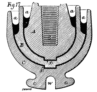
As this process of manufacture represents the best modern practice in the production of high-class porcelain insulators, it will not be out of place to describe more in detail the methods adopted by the well-known Continental firm of Bock. The general forms of the separate portions are shown in Fig. 17, from which it will be seen that the insulator consists of three sections, A, B, and C. The innermost section A differs from the others in being provided with a screw-thread s, which is moulded or pressed into it for the support of the insulator. The outer section C is provided with a groove w, for supporting the line-wire, and c c are the lateral lugs of the outer petticoat. The sections A and B possess projections x which fit in corresponding recesses in the sections B and C, and by means of these it is an easy matter to secure the separate petticoats or bells in their proper relative positions. The Bock process' of manufacture is as follows:--
"The bells A, B, and C are moulded separately, pressed and dried, and baked at a high temperature in the furnace. The mass of the porcelain does not undergo fusion during this process. When cool, the separate petticoats are glazed, fitted I together, and placed with their annular spaces a, a uppermost. These are now filled with glazing material. The whole is then enclosed in a seggar, and exposed in the furnace to an intense white heat until the porcelain settles by partial fusion, whilst the glaze undergoes complete fusion. During this process the mass in the annular spaces a, a fuses down and completely fills the gaps between the sections A, B, and C. The latter are thus fused into a concentric body, as shown in Fig. 17. The access of moisture is thus entirely obviated."
 |
| Fig. 18. |
 |
| Fig. 19. |
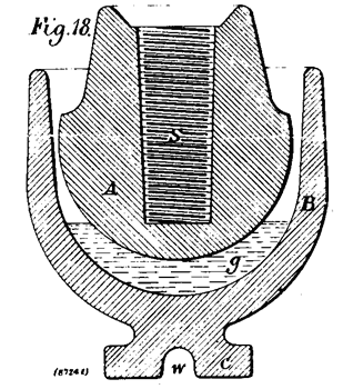
A method which differ but slightly from the Bock process is indicated by Figs. 18 and 19. After the sections A and B have been baked, the hollow of the outer petticoat B is covered with a rather thick layer of glazing material g, into which the inner petticoat A is fitted. After encasing them in a seggar, they are fired in the furnace in the position shown in Fig. 18. After being subjected to a very intense temperature for some time, the glazing material fuses, and the inner section sinks gradually down, whilst the glazing flux is forced up wards until it completely fills the annular space between the two petticoats A and B. By this process it is difficult to avoid the formation of air?bubbles in the layer of glaze between the sections A and B; but as air is in itself a good insulator, it is claimed that this is not a serious defect.
The glazing of porcelain insulators is evidently an important process in their production, and both in the manufacture of the solid and multipart insulator it is essential that the glaze should present a smooth homogeneous surface. To obtain this effect the coefficient of expansion of the glaze should be practically the same as that of the porcelain, otherwise minute cracks will occur in the glaze during the cooling process, or when the insulator is exposed to the action of the atmosphere after removal from the kiln. The existence of these cracks and pores means obviously a diminution of the insulating qualities of the insulator; in fact, they render the insulator defective, inasmuch as the insulator is subjected to variations of temperature when a high potential current is conveyed over the insulator, causing further unequal expansions, contractions, and deterioration. Considerable attention must, therefore, be paid to the glaze-cementation process in the production of multipart insulators, since at the junction surfaces the glaze cement forms thick layers, and it is found that rarely do the coefficients of expansion of the glaze and the mass of porcelain approximate sufficiently to enable the thicker layer of glaze to take a perfectly homogenous vitrified mass, and very frequently the glaze is pierced by numerous cracks. For this reason some engineers do not recommend this method of building up composite insulators, but "prefer having them furnished in separate pieces by the manufacturer, since when the thickness of the porcelain reaches a certain limit, the ordinary testing will not puncture a sound insulator. In testing an insulator made up of two or more pieces, one layer of porcelain may be cracked, but is protected by the other layers. When the tests are performed on the simile composing parts, this cannot happen, and one is sure to have the insulators made up of sound parts. Moreover, each composing part can be better inspected, and the character of glazing observed. Following this suggestion, many makers produce insulators in two parts, which, after test, are put together with glycerine and litharge cement. Experience has demonstrated that it is useless to increase the number of component parts; up to 40,000 volts, two parts are quite sufficient, and above that voltage not more than three are necessary."
Another method of eliminating the defects mentioned has been devised and patented by Mr. Rudolf Gaertner, and insulators of his design are manufactured by the Karlsbader Kaolin-Industrie-Gesellschaft, Carlsbad, Bohemia. In this case the separate bells are so connected with one another that an interstice, or annular space, is formed between them in such a manner as to afford an air-jacket practically enclosing the inner bell, and thereby the number of glazed walls, and also the space between the cable and the support, are increased. The insulator is shown in Fig. 20, and it consists of two bells a and b. The outer bell, or petticoat, a possesses a projecting edge c, so disposed as to fit in a corresponding annular recess d on the inner petticoat. A junction is effected between the two by a layer of glaze fused by an additional heating, leaving between the two petticoats a and b the air-jacket e. As the separate bells are provided with an even thin layer of glaze on their outer and inner surfaces, an insulating layer is provided between the cable and the iron pin or support, which is composed of the porcelain, four layers of glaze, and the air-jacket e. It is evident that by this method of increasing the relative distance between the cable and the iron support, by increasing the number of layers of glaze inside the insulator, and interposing an air space or jacket, an insulator is produced which has great mechanical strength and resistance efficiency.
The inspection of high-tension insulators is also an important matter; generally all insulators are carefully examined on their arrival from the factory, and those with a bad appearance (inferior glaze or are cracked) are put aside. Before using an insulator it should also be subjected to a puncture or breakdown test at a voltage at least twice that to which it will be subjected under normal conditions. It is, however, open to question whether a factor of safety of 2 is sufficiently high, since this value does not leave much margin for contingencies. At Niagara the test pressure is 40,000 volts alternating, the method of making the test being as follows;—The insulators are inverted and set in a hollow iron pan, which is filled with salt water to a depth of 2 in. A small quantity of salt water is poured into the pin-hole of each insulator, and a small metallic rod is placed vertically in the pin-hole, where it, of course, makes good contact with the brine. One pole of the alternating potential is connected to the metal rod, while the other is connected to the pan. Any weakness of the insulator is quickly manifested by a series of sparks, usually followed by a breakdown of the insulator and the blowing of the fine-wire fuse included in the test circuit.
The method of making the wet arcing test—i.e., to determine the potentials that produce arcing across the insulator—is to mount the insulators on tin-covered wooden pins, and to apply increasing pressures taken from a step-up transformer. At the same time a stream of water from a sprinkling nozzle is played on the insulator, the quantity of water thus striking the insulator amounting to ¾ in. per minute. High-class insulators should withstand a pressure of from 75,000 to 100,000 volts before the current jumps across.
