[Trade Journal]
Publication: Electrical Review
New York, NY, United States
vol. 46, no. 22, p. 887-891, col. 1-3
HIGH-TENSION INSULATORS
The Manufacture and Electric Testing of an Important Element of Line Construction.
IN THE early days of the telegraph, when the first transmission of electrical energy was accomplished, the potentials used were so very low that any substance not actually a conductor served as a means of separating the lines from one another as well as from the earth, and so long as the transmission of energy was confined to this class of apparatus, where a short-circuit or leaky line meant nothing more than temporary interruption of service, no great demand was made upon the insulator manufacturer, but once any considerable power was transmitted at higher pressures a faulty insulator or a leaky one came to mean not only a serious interruption to service but ofttimes actual destruction of valuable apparatus and possibly loss of life. Thus has it come about that upon the insulator man falls the responsibility of maintaining uninterrupted service to a vast number of consumers as well as guaranteeing safety to the public and to the operators of the electrical apparatus with which the line is connected.
| |||
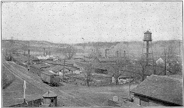
| Bird's-Eye View of the Plant of the Locke Insulator Manufacturing Company, Victor, N. Y. |
In the early days, the brute strength of the insulating materials was brought into service, little or no attention being paid to the more important details of insulator design, a method which will do very well for moderate voltages but entirely inadequate to the task of effectively insulating lines of very high potential, since insulators for lines of very high potential require the utmost care in their manufacture in order that a reliable and trustworthy product may result.
| |||
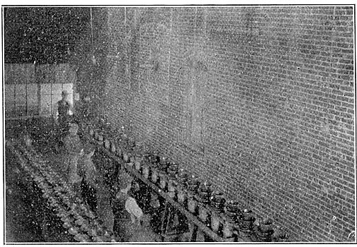
| High-Tension Insulators - One of the Test Racks. |
The pioneer work along this line was done at the works of the Locke Insulator Manufacturing Company at Victor, N. Y., where the "Victor" insulator, used in almost every country of the world, is made, and where the work is to-day carried on along strictly scientific lines, no effort being spared to keep abreast and, if possible, a little in advance of the times.
All high-grade porcelain is made of the very best clays, and the ware of which the modern insulator is made may well be classed as of the highest grade of material; for none but the first quality of clay is used in its construction. From the time the clays are placed in storage bins to the time the finished insulator is shipped from the factory, an expert in this line of work has a watchful eye upon every process and a daily record of all conditions is accurately kept.
| |||
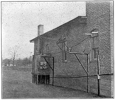
| High-Tension Insulators - the High-Potential Laboratory, Showing Cabin for Wet Tests. |
Having ascertained, by chemical analysis, the constitution of the various clays, the ceramic man's first concern is so to mix them that a body of maximum electrical and mechanical strength shall result, this being attained only by the utmost nicety of adjustment and constant exercise of engineering judgment.
An electrical porcelain pottery is unlike any other kind of works, unlike even any other type of pottery, for not only must drying conditions be carefully watched, but the absence of either mechanical or electrical strength in the finished product brings disaster, before the discovery of which thousands of dollars' worth of ware may have been rendered valueless.
Though very finely ground and apparently in the last stage of subdivision, the clays after having been properly mixed as to quantity of each are placed, together with sufficient water, to form a liquid mass, in a ball mill or large iron tub lined with porcelain brick and half filled with quartz pebbles selected from glacial drift in Iceland. The tub is caused to rotate on its supporting axle and the quartz pebbles still further reduce the clays in, matter of fineness and thoroughness of mixture.
| |||
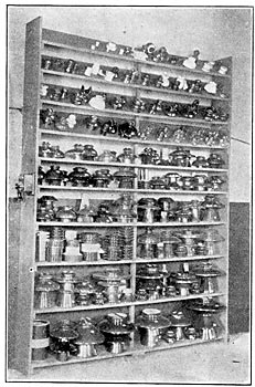
| High-Tension Insulators - Samples of Some of the Products. |
From the ball mill the mixture of clay and water is run through a lawn or 150-mesh screen to a cistern from which it is drawn by means of a power pump and forced into filter presses. Filter presses for this class of work are of the type used in many potteries and consist of a series of cast-iron rings separated by sheets of canvas pierced by a three-inch hole to admit the liquid clay. The canvas sheets so arranged form a series of pockets from which water may readily leak but in which the clay is retained, thus forming "leaves" about thirty inches in diameter. As the pockets become filled with clay the pressure steadily rises until no more can, with safety, be applied. The clay is then ready for working, but to ensure its being homogeneous and thoroughly pliable it is put through a pug null or large sausage machine which forces it through a die under pressure, from whence it emerges as a long "sausage" about four inches in diameter. In this state it is delivered to the potter who is thus furnished with a perfectly pliable and reliable clay upon which to expend his efforts.
The process of drying and firing of electrical porcelain causes it to shrink about fifteen per cent, and accordingly the model of the insulator from which all moulds are made is fifteen per cent larger than the finished piece of ware. Such models are usually turned from blocks of plaster of paris, their surfaces oiled, and the moulds cast from them in one, two or three parts as occasion may require.
| |||
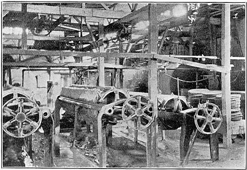
| High-Tension Insulators Filter Presses and Ball Mills, Showing "Leaves" of Clay at Right. |
Having been properly dried the moulds are filled with just enough clay by the potter's assistant and are placed by the potter upon his wheel where the operation of shaping the inner side of the particular piece under consideration is carried on by the aid of the hands and a properly shaped former, which is held in place mechanically, and thus produces a perfectly uniform shape inside. The outside, of course, is determined by shape of the mould. The mould with its clay is now set aside for some hours, during which time the plaster performs its function of absorbing the water of the clay immediately adjacent to it. The clay has now become dry enough to handle and is removed from the mould, carried to the finisher who by means of a revolving table sets the partially dry ware to rotating, a wet sponge and, if necessary, a sharp knife being used to remove any irregularities and produce a smooth exterior. The piece thus finished is now set away and allowed to dry completely, after which it is dipped in a silicate solution, some of which is absorbed by the ware, thus forming a thin glaze or glasslike surface, whose only function is to produce a smooth finish as well as impart color to the insulator. At present a dark-brown color is usually employed because of its supposed inconspicuousness compared to white; however, it is possible to produce any desired color by placing in the glaze the proper coloring matter.
| |||
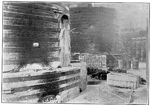
| High-Tension Insulators Two of the Porcelain Kilns. |
In some of the smaller-sized insulators the glaze accomplishes a double purpose, for besides covering the surface of the ware it is made to serve as a cement for fastening the parts together, forming a neat and strong joint, for the glaze liquefies at the temperature at which the body vitrifies.
The kilns in which the ware thus prepared is fired are cylindrical, being about eighteen feet in diameter and sixteen feet high, lined with firebrick, and arranged with fire. bags around the base, the fire from which is drawn over into the kiln and down through the floor thence to the chimney. In order to protect the insulators during firing they are placed in fire-clay receptacles called "saggers," which are piled one on the other until the inside of the kiln is completely filled, after which the entrance to the kiln is bricked up and sealed with fire-clay mortar. There remains now but to raise gradually the temperature to the required degree, which point is made evident by the fusing of small porcelain cones placed at regular intervals about the kiln, an opening being left so that ready access may be had to them. Before each opening are placed four cones which fuse at various heats, and in firing a kiln the temperature is raised till three of each set of cones are fused and the fourth very nearly so. In watching the cones the heat is so intense that a man can not face it unprotected and the light is so dazzling that a colored hand-glass is necessary to soften it so that the eyes can endure it. A thorough knowledge of the exact rate at which the temperature rises has been found very important, and for this purpose one of the famous Le Chatelier pyrometers has just been installed. This has a very delicate electric galvanometer which is connected with a platinum-rhodium thermo-couple projected into the kiln. By means of this instrument the temperature can be determined with absolute accuracy. With this knowledge at hand the temperature is raised with such regularity that no unnecessary strains are created in the ware by sudden variations in temperature. The heat within some parts of the kiln is so intense as to fuse the firebrick with which sides are lined. The proper heat having been attained the fires are allowed to cool down and the annealing process carried on until an insulator absolutely free from internal strains is assured. The door is broken down and the finished insulators pass from the ceramic to the electrical test and shipping departments.
| |||
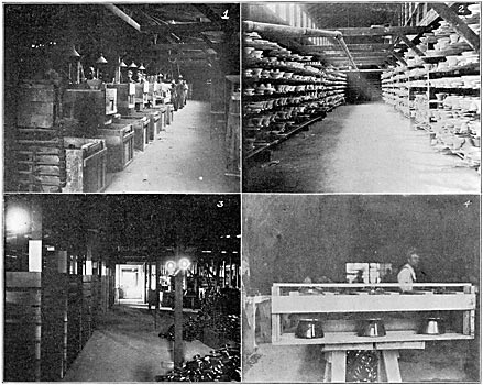
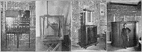
| High-Tension Insulators 1 View in Green Ware Finishing Department. 2 Ware Drying. 3 View in Stock Department. 4 Insulators Crated for Shipment. |
ELECTRICAL TESTING OE HIGH-TENSION INSULATORS.
Insulators designed to carry more than 5,000 volts are subjected to a high-voltage test before leaving the factory. The voltage to which any insulator or part is subjected is usually made as high as it can be conveniently raised without the annoyance of flashing over. The length of time which such test is applied is usually about one-half to two minutes, according to the purchaser's specifications. Insulators or parts to be tested are inverted in a pan of salt water and a chain from the high-tension wire directly overhead is dropped into the water with which the insulator is partially filled. The pans in which the insulators are inverted are about thirty-five feet in, length and enough chains are provided to test as many as thirty large insulators at once on a single rack, additional racks being provided which may be switched on and off by means of a large air-break switch, thus allowing a transformer to be run continuously, eliminating any waits while loading or testing a rack of insulators. In order to avoid danger of injuring workmen employed about the test, the pans in which the insulators are placed are operated at earth potential so that all danger is confined to the chains and their supporting conductors.
It is customary to test all parts of an insulator separately before cementing, in order that only perfect parts may be used and also in order that on the final test the failure of a single part may not necessitate the throwing away of a complete insulator, for once the hydraulic cement used for this work becomes set it is impossible to separate the parts without destroying them.
The object of the electrical test is to seek out all defects not visible to the eye, such as minute cracks or soft spots in the body of the ware, and to do this with certainty it has been found necessary to provide a testing equipment with large capacity in order that a moderate draught of current from the secondary shall not reduce its voltage to a low value.
| |||
| High-Tension Testing Transformer. |
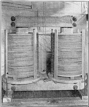
At the Victor factory the test voltage is supplied by a 200-kilowatt 300,000-volt transformer which is capable of operating as high as 500,000 volts potential and is designed to carry 100 per cent overload for a considerable time. This transformer is of the core type with an iron section of approximately 100 square inches. Normal operation of the transformer at 300,000 volts requires 1,100 volts on the primary which is made up of four sections to obtain flexibility in connections. The secondary is wound in large flat coils utilizing approximately forty-two miles of No. 26 B. & S. wire; the ends of the windings being available it is a matter of but a few moments work to change from series to parallel connections. This constitutes by far the largest piece of test apparatus of its kind in the world and is in constant use for commercial testing as well as experimental work.
There is available for use with the testing equipment 600 volts from a thirty-kilowatt, sixty-cycle, two-phase Stanley alternator; 1,100 volts from a General Electric sixty-cycle A. T. B., and 400 volts at twenty-five cycles direct from the substation of the Rochester & Eastern Rapid Railway. Normally the transformer is operated with current from the motor-generator set which has a capacity of 200 kilowatts, but for limited periods of time power may be drawn from the railway company to the extent of 500 kilowatts. By this means it is possible to fulfill almost any test requirements.
| |||
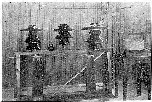
| High-Tension Insulators, Testing Department. 1 Distribution-Board. 2 Electrostatic Voltmeter. 3 Portable 50-Kilowatt, 200,000-Volt Transformer. 4 500,000-Volt, 200-Kilowatt Transformer. |
Adjacent to the commercial test and packing room is the special test and research laboratory, a fireproof building twenty-one feet by forty-eight feet. The floor is of heavy concrete construction so that the vibration of heavy machinery will not be communicated to any delicate measuring instruments. One part is reserved for machinery and transformers, while the other is used as an exhibition and test room, where experiments with the highest voltages may be carried out. The necessary switches and controlling rheostats are located in this room, the high-tension wires entering through large porcelain tubes extending to spark-gap and test rack. As this room may be darkened all experimental work is carried on here to witness better high-tension phenomena. For ordinary measurement of high voltages an ordinary spark-gap fitted with sharp needles is employed, but for the sake of a greater facility a simple electrostatic voltmeter has been designed which will measure voltages up to 250,000 without difficulty and with considerable accuracy. It consists merely of a glass jar filled with oil in which are submerged two plates, one being movable and carrying a light vertical plane mirror. The plates are connected so as to be at the same potential, which upon being applied causes the movable plate to swing away from the stationary one, the amount of such deflection being observed by means of a cross-hair telescope and a scale as in an ordinary galvanometer. Any degree of sensitiveness is obtained by varying the distance between the fixed and movable plates. This device greatly facilitates the test of insulators or test plates, as the spark-gap is slow to operate, and is as well subject to considerable error if the needles happen to become burned.
In order to be able at all times to keep a watchful eye upon the ware a novel testing device has been designed. These are plates of ware which dry and are fired much more quickly than the regular insulators and are tested several days in advance of the time when the insulators of that particular "mix" enter the kiln. If, then, for any reason, the dielectric strength is low it is known before the clay has been rendered useless. To accomplish this a large porcelain basin filled with oil, supported upon a suitable table, is utilized. In the bottom of the basin a needle-holder is arranged and connection made to one terminal of the testing transformer. Over the basin a small framework supports the other terminal of the transformer which also terminates in a needle point. Needles are used in order that the radius of curvature may be made as important as possible in the various tests.
A plate having been inserted the upper terminal is lowered till the needle touches the surface of the porcelain and the voltage raised till puncture occurs, the voltage being observed by the voltmeter. The plate is then taken out, broken and carefully measured by means of a micrometer. This system of always being forewarned of any fault in the product leads to some very interesting results and yields much positive information regarding the dielectric strength of porcelain and the factors influencing it.
All research on dielectric strength of insulators or similar work is carried on inside the laboratory, but in order to test line insulators under nearly the same conditions to which they will be subjected when in service a cabin has been constructed just outside the laboratory which is fitted with steam and water pipes for humidity and precipitation tests. As this cabin is entirely dark and covers one of the windows of the laboratory, the applied potential may be regulated by the observer, darkness here as in other high-tension experiments aiding materially in observing the phenomena. Much work along the line of experimenting with various forms has been done in an effort to ascertain the best form of construction as well as the lines along which progress is most desired.
| |||
| High-Tension Insulators Experimental Testing Rack and Oil Tester. |
In the machinery room of the laboratory are located the transformers, generating set, and controlling switchboard. All power and lighting circuits are controlled from this point, and by a system of plug connectors any combination of circuits may be secured.
For power, current and voltage measurements, Thompson inclined coil instruments are utilized. For very small secondary currents, a voltmeter calibrated for current is introduced at the point of earth potential of secondary winding, at which point the current coil of the wattmeter is also introduced, the wattmeter voltage coil being placed across the primary; the fact that primary and secondary voltages are at 180 degrees justifying this method of measurement.
| |||
| High-Tension Insulators 200-Kilowatt Motor-Generator Set. |
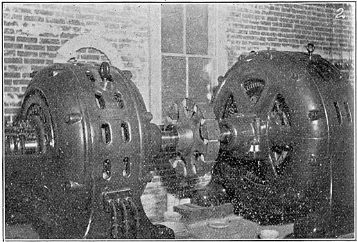
The motor-generator set, which is standard General Electric apparatus, is ordinarily operated direct-connected, but for purposes of special test at lower or higher frequencies belt and countershaft connections furnish means by which any requirement may be met.
In all factory tests it is, of course, possible to make use of the large 200-kilowatt transformer, but in cases where testing must be done at the point of erection a portable transformer is very desirable. To meet this demand the engineering department of the company has constructed a fifty-kilowatt 200,000-volt transformer which has been designed to withstand the rough usage incident to a freight traffic. Primary and secondary connections are so made that practically any voltage from 110 to 1,000 may be made to yield the required secondary potential for purposes of test.
The foregoing shows in a general way that the work of making and testing insulators at the Victor factory is laid out on scientific lines, combining ceramic and electrical skill with economical factory operation, in an endeavor to put insulator production upon the high plane of other electrical industries.
Efforts are not confined to the manufacture of line insulators, though doubtless the exhibit room would show greater variety of such insulators than could be found elsewhere, but every branch of high-tension work is thoroughly gone into and the possibility of the adaptation of porcelain to its service investigated.
The ideal aimed at is to produce a perfectly uniform product as to color and quality, and no effort is being spared to gain and merit the confidence of electrical engineers who are coming more and more to look to the specialist for a solution of their line troubles.
