[Trade Journal]
Publication: Elektrotechnische Zeitschrift
Berlin, Germany
p. 563-569, col. 1-3
Electricity works of the city of Drammen.
By Mrs Thrue.
(end of p. 533.)
Switchgear and connecting lines. Triple-stranded, iron-tape-reinforced lead cables of 370 sq. mm lead from the generators to the switchgear.
The cables are laid on the floor of the wide, walkable cable duct, with plenty of mutual space and can be covered. They are led up below the resistance room and are placed on the wall in the transformer room after the equipment above. The supply lines to the magnet coils of the generators are laid on rollers as vulcanized rubber core cables and mounted on simple angle iron frames on the ceiling of the duct. These frames take up a maximum of half the width of the cable duct. The cables between the excitation dynamos and the switchgear are also laid in the cable duct as bare copper bars and vulcanized rubber core cables. The design of the switchgear, the diagram of which is shown in Fig. 12, was based on the greatest possible simplicity and clarity with regard to operation. As can be seen from the circuit diagram, each generator was given three single-pole fuses, voltmeters and ammeters with voltage and current transformers, as well as a three-pole switch, and also an ammeter and a regulating resistor with carbon switches for the excitation circuit. The generators work on three busbars, which can be divided up later, and from which the power required for three-phase motors installed in the primary station is still drawn.
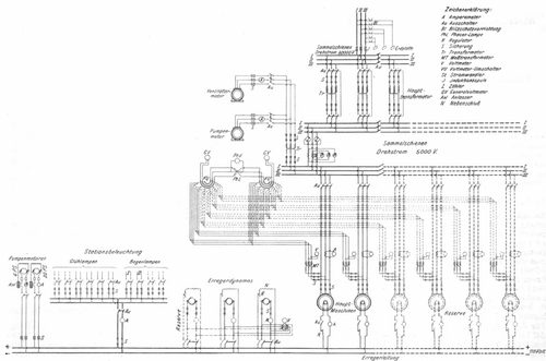 |
| Fig. 12 |
The transformers for stepping up the current are connected to a second subdivided busbar system, which is connected to the first via three collective ammeters and two meters. The latter only have switches and fuses on the 5000 V side and the 20000 V side; the former are coupled together. The transformers operate secondarily on subdivided busbars from which the long-distance lines originate. The long-distance line has a choke coil for each phase, two horn lightning arresters connected in parallel, and a device which uses a continuously flowing water jet to divert any overvoltages to earth. For parallel connection of the generators, two general voltmeters that can be switched to each machine, as well as a synchronization device with phase voltmeter and lamps are provided, which also indicate whether the machine to be connected is leading or lagging. Small motors that can be controlled from the control panel , the turbine regulator of the machine in question is then adjusted and synchronism is brought about. Each exciter dynamo is provided with fuses, ammeters, double-pole switches and regulating resistors with carbon switches; all have a voltmeter with changeover switch. The station lighting and two pump motors are also connected to the exciter busbars . When designing the switchgear, the requirement that the parts of the system requiring constant maintenance and operation should not pose a danger to the operating personnel was met by accommodating all high-voltage cables and devices in a lockable room behind the instrument panel and by Measuring instruments for low voltage were installed, and the regulating resistors and meters, which required frequent checks, were installed in a special room containing only low voltage.
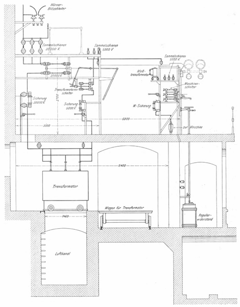 |
| Fig. 13 |
The control room is 3.3 m above the engine room floor; its width is 10.8 m, its depth 5 ,9 m, to which 1.6 m must be added for the service corridor in front of the switchboard. The switchboard for the machines with the fields for the busbar instruments forms the end of the machine room; behind it, separated by a wide corridor, The equipment frames for the transformers are located there; the lightning rod gallery runs above the latter. All equipment frames were manufactured from the outset to suit the full expansion of the system. A cross-section through the switchgear is shown in Fig. 13.
The machine switchgear includes the equipment on the upper floor and that in the resistance room. On the upper floor there is an iron frame 2.4 m high, which is divided into ten sections and has two side doors on the same level as the front wall. The ten sections are each 900 mm wide and lined with white marble panels from 0.7 m above the floor; the cladding underneath and the two door panels are made of perforated iron sheet. The first section on the left is intended for the equipment and instruments of the three excitation machines, the second section for the collective instruments; sections 3 and 4 each accommodate the equipment and instruments for one generator. The remaining six sections are intended for four further generators and two further long-distance lines, or the collective instruments for these. All fuses, current and voltage transformers, the high-voltage switches as well as the voltmeter switches and the cables are behind the panel. The excitation panel contains on the front the ammeters, the common voltmeter with changeover switch and the switches for the excitation dynamos, as well as the handwheels and levers of the shafts leading downwards to the shunt regulators.
The collector panel contains the three collective ammeters, which also indicate the line load and according to whose information the regulation takes place; furthermore the voltmeter changeover switches for the general voltmeters and a small switch for the synchronizing lamps are mounted on the panel.
Each generator field shows a voltmeter, an ammeter, the switch lever protruding through the marble slab and below that an ammeter for the excitation, a handwheel and lever for the regulating resistance and a small switch for the regulator motor.
The general voltmeters and the synchronizing device are mounted on a wall bracket to the left of the field of the excitation dynamos, at the end of the panel, in such a way that they can be easily observed from any point in front of the panel. The high-voltage switches are pull switches from the Oerlikon machine factory for current interruption in an airtight manner. During the acceptance tests, the machines were switched off at full load and full voltage without the switches showing signs of fire or burns. The switchgear for the transformers consists of two sections separated from each other by a corridor, from . the one facing the machine switchgear contains switches and fuses for the 5000 V lines, while the second contains fuses and switches for the 20,000 V lines.
The switches used for 5000 V and 20,000 V were pull switches, whereby the switches belonging to a transformer are coupled together so that both sides are switched on or off at the same time. For the 20,000 V side, fuses were used in which the melting wire is placed in a container partially filled with oil, just above the liquid, and when it melts, is drawn into the liquid by spring force.
 |
| Fig. 14 |
 |
| Fig. 15 |
The long-distance line is connected to the 20,000 V busbars. Inside the station, it is protected against overvoltage by means of induction coils with lightning protection devices and safety devices. Each of the three conductors that lead up the gable wall of the engine house has two parallel lightning arresters that are accessible from a gallery above the transformer switchgear, and a line also leads from it to a water resistance that is formed by a jet that flows continuously into an earthed container. The long-distance line leaves the station through an output tower that is located directly above the switchgear. The output from the tower is through glass plates that are protected against rain as far as possible. The output tower is accessible via a ladder from the side of the building facing the water tower. All iron frames, the instrument housings and the metal parts of the equipment are well connected to each other and to earth.
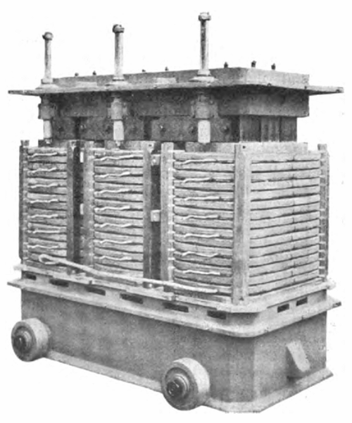
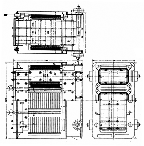
Transformers. To transform the current from 5000 to 20 000 V, three three-phase transformers with artificial tension for 770 KVA each were installed, with one transformer serving as a reserve. For later expansion, larger ones are also used, corresponding to the larger generators. Transformer units The cooling system is designed from the outset for full expansion. The transformers, the design details of which can be seen in Fig. 14 and 15, have an iron body with vertical cores of rectangular cross-section with two air gaps arranged between the sheet metal packages. The low-voltage coils, consisting of 158 turns of bare copper measuring 8x6.5 mm², are first applied to the cores. The turns are arranged in two layers and insulated with pressboard. A closed jacket made of impregnated paper with mica inserts using a special process is placed around the low-voltage coils. The high-voltage windings, which consist of 15 individual coils with 42 turns each, rest on this jacket. Each turn consists of two parallel wires of 3.6 (4.0) mm diameter. The insulation jacket between the low-voltage and high-voltage windings extends well beyond the winding at the top and bottom to prevent the voltage from flashing over. The transformers met the following guarantee figures: Efficiency at
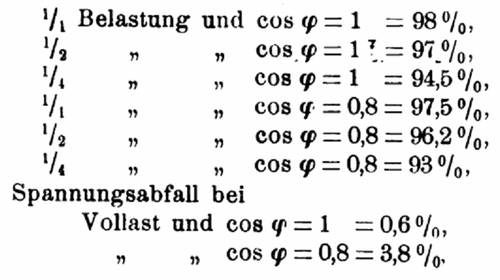 |
The no-load loss is 10 KW or 1.3% of the normal output. The temperature increase during continuous operation and full load is no more than 50° C. The overload capacity is 25% for two hours.
The insulation test was carried out with 30,000 V between the high-voltage winding and the frame, as well as between both windings. The low-voltage winding was tested with 10,000 V against the frame.
As already mentioned in the description of the building, the transformer room is located on the northern gable wall of the building under the switch room. In the room, which is designed for full expansion, the transformers are in a row next to each other. Since each is directly below its equipment frame, the length of the connecting cables is only short, while at the same time the greatest possible clarity is achieved.
The transformers stand on a concrete foundation in such a way that each one can be pulled out of the row onto a trolley for repairs and transported on rails to the winding room.
The duct for the supply of cooling air runs under the foundation (Fig. 13).
A fan is installed at each end of the duct, but only one of these needs to be in operation, while the second is in reserve. The drive motors are fed by a special three-phase transformer. Two chambers extending over three floors are provided to accommodate the fans, motors and transformers. These serve to suck in the cooling air and are completely closed off from the machine room. The air supply to each individual transformer can be carried out from the transformer room by adjusting blinds that are built into the individual branches of the main duct; an indicator shows the respective degree of opening of the flaps. The warm air escapes through the windows in the transformer room.
B. Long-distance line.
Power line. The transmission line is designed to transmit 1800 HP with an energy loss of about 11%. It has a single length of about 35 km and consists of three semi-hard drawn copper wires, each with a cross-section of 25 mm2. The wires are arranged in a triangle and twisted by 1/3 of a turn at intervals of 5.8 km, so that the line makes two full turns in total. The rods and equipment have been prepared for the installation of a second line. Starting from the main station's control tower, the line runs past the water castle, crosses Storelven directly above the Gravfos and shortly afterwards crosses the Drammen-Randsfjord railway. It then turns south and follows the course of the river and the highway in a north-south direction, but remains at a greater distance from both. About halfway, at Haugsund, the line then turns sharply to the east-southeast and follows the river and the highway in this direction to Drammen. The distance between the masts was specified to be 35 m. At the intersection of the highway and wider roads, protective nets had to be installed, while on narrower roads it was sufficient to make the masts on both sides so high and so close to the road that a torn wire could not hang down less than 4 m above the road. Wooden masts were mostly used, but in some places iron lattice masts were also used.
 |
| Fig. 16 |
 |
| Fig. 17 |
| |||
| Fig. 18 |
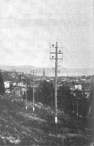
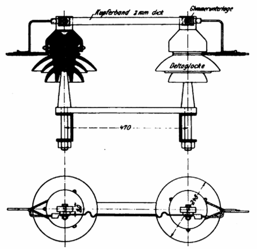
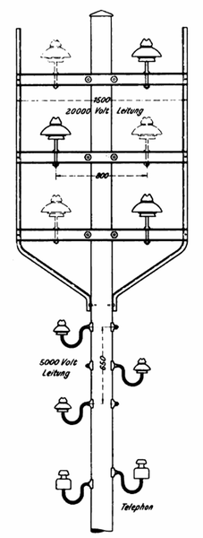
At ten places, line switches were installed on lattice masts, so-called switch masts, the details of which can be seen in Fig. 16. The wooden masts are approx. 12 to 18 m long with 18 to 20 cm braid thickness. They stand in rockfall and are coated with several coats of carbolineum that reach above the ground; Each mast is also covered with a cast iron cap. The line is laid on delta bells with brown glaze. The insulators themselves are mounted on iron crossbeams, which are designed to accommodate three further insulators for the second line, which is to be laid later. They are attached to the mast by flat iron brackets and are connected to one another by an angle iron frame, which is also designed as a safety frame (Fig. 17 and 18). In the iron masts (Fig. 19), which carry protective nets, the screws connecting the frames to the crossbeams also serve as fastenings for the supporting wires of the protective net; the protective net therefore surrounds the lines on both sides and below.
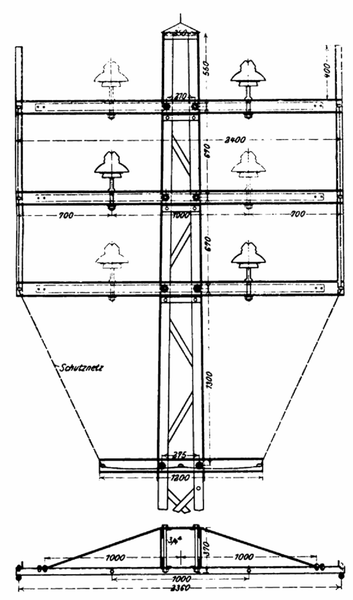 |
| Fig. 19 |
Below the safety frames, each mast carries two small porcelain insulators for the telephone line.
| |||
| Fig. 20 |
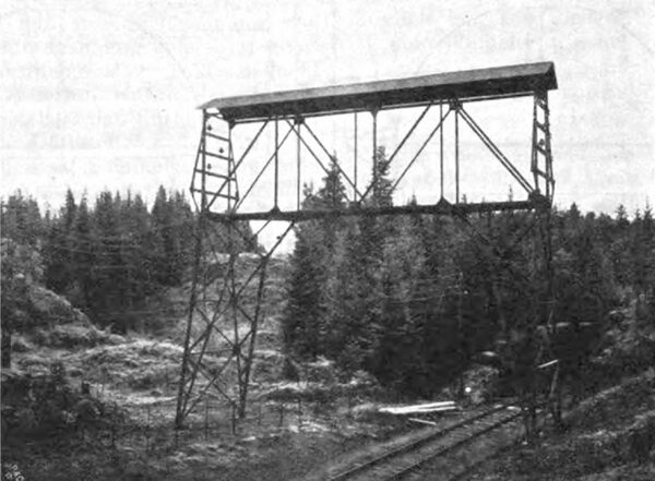
A covered iron overpass bridge (Fig. 20) had to be installed to cross the railway near the primary station.
C. Secondary station.
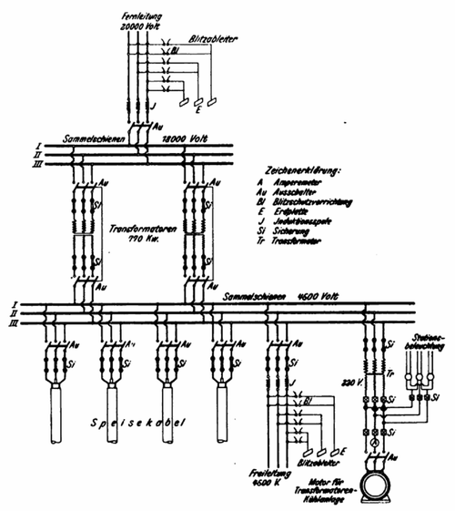
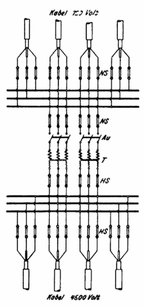
The substation into which the long-distance line is introduced serves to reduce the voltage from 18,000 to 4,500 V, at which voltage the current leaves the secondary station again. For the time being, two transformers of 770 KVA each have been installed; however, the station is designed to accommodate six such transformers. The circuit diagram of the substation is shown in Fig. 21.
 |
| Fig. 21 |
The long-distance line is equipped at the entry point with two parallel-connected horn lightning arresters per phase in conjunction with a device for discharging any overvoltages that occur, as well as with three induction coils and a three-pole switch, and is connected to the high-voltage busbars.
The transformers fed by these rails are connected secondarily to the busbars for 4500 V !, from which four cables and an overhead line extend. A station transformer also receives power from these busbars, which supplies three-phase current of 220 V to operate the motor for the cooling system and the station lighting.
The substation was housed in a three-story brick building.
The long-distance line enters the building on the top floor, and this is where the lightning protection devices, the induction coils and the switch for the incoming line are installed, as well as the lightning protection devices with induction coils for the outgoing 4500 V overhead line.
The transformer switchgear and the switchgear for the outgoing cables are housed on the middle floor.
The transformers and the equipment required for the cooling system are on the ground floor.
The line is introduced into the rear wall of the building using drilled glass panes. A projecting, steep protective roof serves as protection against rain and snow.
The equipment in the substation corresponds to that of the power plant.
The transformers are also of exactly the same design as those in the primary station.
The station is lit by incandescent lamps. The lamps on each floor are in one circuit; the switches for these three circuits are mounted together with three fuses on a small marble slab right next to the main door.
D. High-voltage distribution lines.
Air line. The air line for 4500V leads to two brick transformer stations, which are located close to the main line outside the city proper. The main line masts could be used for laying the line for a short distance from the secondary station (Fig. 17 and 18); the branches after the two stations only required the installation of a few masts.
The line is made of semi-hard drawn copper with a cross-section of 25 mm² and is laid on brown glazed delta bells. The bells are mounted on curved iron supports below the main line's catch frame, but above the telephone line.
Cables. The majority of the secondary high-voltage distribution lines are underground cables with a total length of about 13 km.
Four cables run from the secondary station, two of which branch off in each of the two parts of the city separated by the river.
The two cables to the southern part of the city cross the river near its narrowest point, where they were sunk to a depth of about 18 m.
The cables supplied by the General Electric Company have stranded conductors with a cross-section of 3 × 16 to 3x50 mm², paper and jute insulation, lead pressing and iron tape reinforcement. They are laid in 70 cm deep trenches, separated from each other by bricks and covered.
The cables were tested after laying at 1-1/2 times the operating voltage.
The insulation resistance was 3000 megohn per kilometer, measured at 15° C with 120 V direct current.
 |
| Fig. 22 |
The flux cables have conductor strands of tinned copper wire with insulation of vulcanized rubber and a wrapping of rubberized tape; in addition to the lead sheath and the iron tape armor, there is also reinforcement of 5 mm thick round steel wire.
E. Single transformer stations.
There are a total of 14 individual transformer stations in which the voltage is further reduced from 4500 V to the operating voltage of 220 V. 12 are constructed as iron columns and 2 as brick stations.
 |
| Fig. 23 |
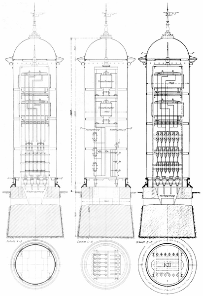
The equipment of the iron transformer stations, which are designed for underground input and output of the lines, is shown in Fig. 22 and 23. Each is designed to accommodate two 50 KW transformers, the necessary switching devices for the transformers, as well as for the incoming and outgoing cables.
The stations stand on a concrete base on which the iron frame for holding the transformers and devices is anchored. The casing hangs above this frame, rotating in a pivot bearing. The casing has wide double-leaf doors on opposite sides, namely upper doors which provide access to the transformers and lower doors which provide access to the devices.
Good ventilation is provided, as air can enter the bottom of the rotating casing along the entire circumference and exit through numerous openings hidden under the cornice of the protective roof.
When installing the transformer columns, attention was paid to strict separation of high and low voltage and to a clear arrangement of all parts. Furthermore, the installation was designed in such a way that the light and power operations can be separated by easily dividing the aluminum busbars; each of these operations receives its own transformer. This separation was only necessary at one station.
On the high-voltage side, the cable end caps for the incoming and outgoing cables are mounted directly above the base. The high-voltage fuses for the cables and the transformers are arranged in three rows above this, so that the fuses of the same phase are next to each other. The three busbars are screwed directly onto the fuses, so that no connecting cables are required and there is great clarity. From the low-voltage side of the transformers, rails lead downwards to three-pole lever switches and from these to the fuses, which in turn are mounted in three rows one above the other and directly on the busbars. The end caps of the low-voltage cables are then mounted below the fuses.
The column is illuminated by two light bulbs mounted between the switches.
The iron frames and transformers are well earthed by copper plates sunk into the ground.
The brick transformer stations, which are located outside the actual city area, are built on rubble stone foundations and covered with zinc. Each house has an iron door and a window above it; ventilation is also provided by bricked-in pipe sections.
The 4500 V overhead line is introduced through glass plates 6 m above the ground. The line then runs down the wall inside, over induction coils and fuses to the transformer. Before the induction coils, the cables branch off to three horn lightning protection devices. The latter are mounted on an iron frame next to the cable, at a height that allows good inspection. The rest of the switching equipment is similar to that of the iron columns.
F. Low-voltage distribution system.
The low-voltage network consists partly of cables and partly of overhead lines.
The cables with a conductor cross-section of 35 to 70 mm² have impregnated fiber insulation and, like the high-voltage cables, were laid in 70 cm deep trenches with a brick cover.
The overhead lines do not run directly from the iron transformer columns, but are connected via underground cables. These cables lead to iron cable guide masts. The latter are clad and covered with sheet metal up to 2 m above the ground. The cable end closure and three fuses above it are mounted within this cladding, which are accessible through a small door. From these fuses, cables lead through the roof to the upper part of the mast, which is also clad with sheet metal. Induction coils are mounted in this upper part, from which short cables lead through the cladding to the guy insulators of the overhead line. Small roller lightning conductors for the cables are mounted on the outside of the sheet metal cladding. The lightning conductors and the mast have a common ground plate.
