[Trade Journal]
Publication: Cassier's Magazine
New York, NY, United States
vol. 28, no. 3, p. 171-190, col. 1-2
ELECTRIC POWER DEVELOPMENTS IN MEXICO
By Francis O. Blackwell
THE conditions in Mexico are peculiarly favourable for the hydro-electric development of power, as fuel for the generation of power from steam is expensive. The supply of wood in the settled portions oi the country is now nearly exhausted, and coal at ports on the Gulf of Mexico costs about S6.00 gold a ton, while in the interior the cost of transportation increases the price per ton from $10 to $20. The country is mountainous, and, though no large rivers exist, high waterfalls make many developments possible.
In common with all tropical countries, Mexico has a wet and a dry season, and the flow of the streams is extremely variable. In general, in order to obtain a reliable power of large proportions, it is necessary to construct storage reservoirs to conserve the flood waters of the rivers for the dry season. The value of a Mexican water power generally depends very largely on the possibilities of obtaining storage for this purpose.
The industries of Mexico are varied and are growing rapidly. Agriculture and mining have been, in the past, the chief sources of the wealth of the country, but, under the liberal and patriotic administration of President Diaz, manufactures of all kinds have sprung up and their number is constantly increasing. In addition, many of the old mines, long thought to have been worked out by the Spaniards, have been reopened and successfully worked on a large scale with modern methods and improved processes for reducing the ore.
Cheap power also makes it possible to economically mine from greater depths, to cope with large quantities of water and to successfully handle ores of lower grade than those worked a few years ago. Many new mining districts are being discovered which can profitably be worked only on a large scale by water power. The country is already being benefited by the utilization of some of its water powers, but the field is such a large one that the work has only just begun.
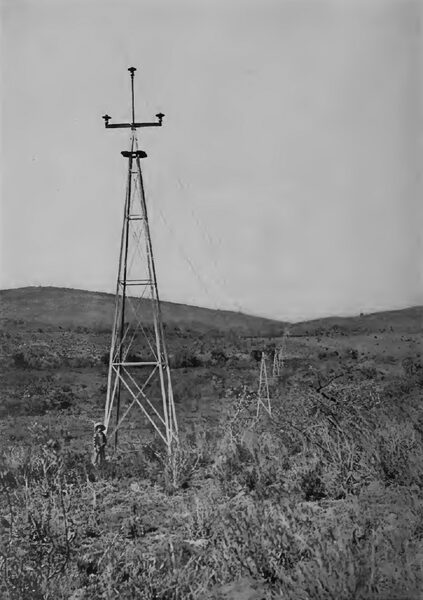
| |||
| Along the Tower Line of the Guanajuato Power & Electric Company. Built by the Aermotor Co., of Chicago, Ill. |
The first water power electrically developed in Mexico was at the Falls of Juanacatalan in 1901. At that time this plant was the largest of its kind, it used the highest potential, and from it power was transmitted for a longer distance than in any other installation in the world. At Juanacatalan the Lerma River has a fall of fifty feet. By installing turbines belted to two 300-KW single-phase alternators, with a periodicity of 100 cycles per second, power was generated and transmitted over an iron- pipe pole line to the city of Guadalajara a distance of seventeen miles where it was used principally for lighting. The transmission potential was 5000 volts, extraordinarily high for that day. This plant was successful and has since been much enlarged. By building a dam across the outlet of Lake Chapala the largest lake in Mexico the minimum flow of the river was subsequently considerably increased and the plant made much more reliable.
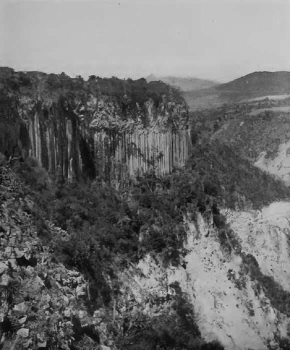
The next step in the progress of hydraulic construction was at Regla, where a high-head water-power plant with multiphase apparatus was constructed along modern lines in 1895. By building a canal, 11-1/2 miles long, with eleven tunnels, in the Barranca of Regla, an effective head of 800 feet was obtained. This was carried to the power house by 2200 feet of 30- inch pipe. Five impulse water wheels, each of 400 H. P., and running at 600 revolutions per minute, were installed in the power house and directly connected to an equal number of 300-KW three-phase alternators. The current obtained from the generators at 700 volts was stepped up to 10,000 volts and transmitted over a steel pole line seventeen miles to Pachuca. The power was used in Pachuca principally for operating the mines of the Rio del Monte Company and the mills and reduction works in the city.
| |||
| The Barranca of Regla. the Canal and Tunnels for the Pachuca Power Plant Are in the Foreground Under the Basaltic Columns, Though Not Readily Discernible in the Illustration |
| |||
| The First Necaxa Falls, Showing the Engineers' Camp Above and the Construction Plant Below |
| |||
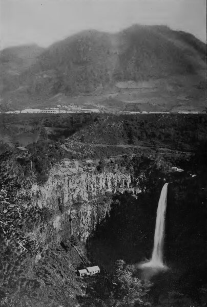
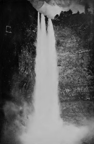
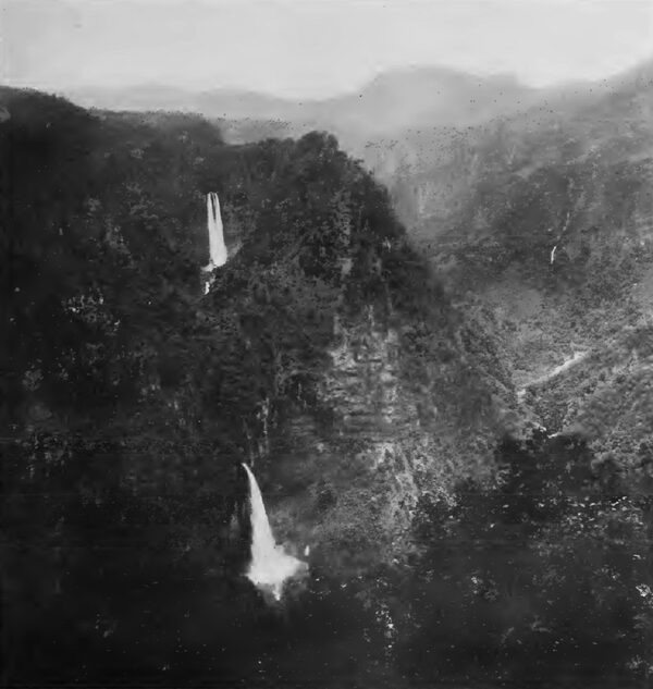
| The Second Necaxa Falls, 740 Feet High. A Cage for Lowering Machinery to the Power House. is Shown in the Upper Left-Hand Corner |
| |||
| The 6-Foot Feeders Between the Tunnels of the Necaxa Plant, in Process of Construction |
| |||
| Tenango Falls, Which Played An Important Part in the Necaxa Development |
The next important advance in power transmission was made in the plant of the Guanajuato Power & Electric Company, which has been in operation since 1903. This company constructed a power plant near Zamora, where, by excavating five miles of canal and laying 3300 feet of pipe, a head of 320 feet was obtained. Two units are installed, each consisting of two 1125-H. P. impulse wheels and a 1250-KW, 60-cycle, three-phase generator running at 200 revolutions per minute. The current from these machines is raised to 60,000 volts by three 10S0-KW oil transformers and transmitted no miles over a single circuit to the city of Guanajuato, where the power is used in the silver mines and mills. The capacity of this plant is now being doubled by the addition to it of 5000 H. P. This transmission is notable for its length and because it is the first in which an all-metal line construction, long spans and a potential of 60,000 volts were used. The towers are of galvanized steel with 3-inch x 3-inch x 3-16-inch corner angles, 8 feet apart. The spans are of 440 feet, and occasionally longer, up to 1500 feet. The conductor is a 19-strand copper cable equivalent in cross section to a No. 1 B. & S. wire. The cable is supported by 14-inch, 3-part porcelain insulators, and cast-iron pins at heights of 41 and 47 feet from the ground, with a sag in the conductor of 10 feet. A telephone line is carried by the same towers and keeps the two ends of the plant in constant communication.
| |||
| The Valley Above Salto Chico, Showing the Necaxa Pipe Lines and Tunnels. |
In tropical countries the use of wooden poles is objectionable on ac- count of their short life. In Mexico the cost is also excessive as they must be imported from the United States. The substitution of steel not only reduces the first cost but also gives a strong, permanent and fire- proof construction, making the line much less liable to interruptions. The towers are also conveniently handled in a mountainous country, as they can be knocked down and packed in bundles for mule-back transportation and assembled at the points where they are to be erected. With long spans the less number of insulators is also an advantage, in that it permits a larger and safer insulator and higher potentials to be employed than is possible with short spans.
The latest plant now under construction is that of the Mexican Light & Power Company at Necaxa. It will be one of the largest power plants in the world, and, in addition, will deliver power over a greater distance than has yet been undertaken by any other installation. The Tenango and Necaxa Rivers drain a portion of the central plateau on which the City of Mexico is situated, and, at a point about 100 miles northeast of the City, pass through the mountains at an elevation of 4300 feet above sea level. A few miles below the town of Necaxa the Tenango River flows into the Necaxa River and eventually discharges into the Gulf of Mexico about sixty miles farther East.
There exists on both rivers a remarkable series of waterfalls with a total drop of about 3000 feet in 3 miles. The rivers have a combined drainage area of 227 square miles upon which the rainfall varies from 85 to 135 inches per year, most of it being concentrated in the rainy sea- son from May to December. The combined flow of the streams is, as might be expected, extremely variable, the minimum recorded flow being one cubic metre a second and the maximum 90 cubic metres. The average flow during the year of lowest recorded rainfalls was about 7 cubic metres per second.
The plan of development decided upon was to turn the Tenango River into the Necaxa by means of a diverting dam, i6J feet high and 280 feet long, and a tunnel 11x7 feet in cross section and 3000 feet long. A favourable location for a large storage reservoir exists at Necaxa, making it possible to equalize the entire flow of the streams during a dry year. A short distance below the site for the reservoir there are two falls in the Necaxa River, one 300 and the other 750 feet in height, which, together with the rapids above and be- tween them, give a total fall of 1300 feet in a mile. The initial plant will utilize this head, but there is a further fall immediately below of 1300 feet which will be developed as soon as the first plant is completed. The two plants will eventually be capable of furnishing 80,000 electric horse-power.
The ground at the site of the dam is an unreliable volcanic rock, and, as no rigid bottom exists upon which to build masonry, an earth dam has been decided upon. This dam will be 177 feet high and 600 feet long at the crest, with a width at the base of 950 feet, and at the top of 54 feet. The slopes will be 3 in 1 on the up stream and 2 in 1 on the down stream faces. About 2,000,000 cubic yards of material will be required in its construction, and will be obtained from the neighboring hills and sluiced into place by the methods that have been so successfully used in many hydraulic fill dams in the Western part of the United States under similar conditions.
| |||
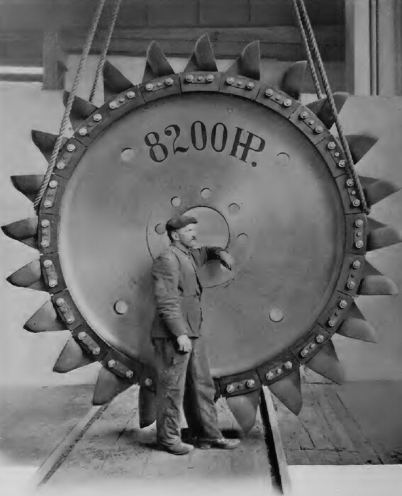
| One of the 82do-H. P. Water Wheels Built for the Mexican Light & Power Company by Escher, Wyss & Co., Zurich, Switzerland. |
The hydraulic system originated in the placer mines of California and is the most rapid and economical method of excavating and transporting large quantities of earth and rock wherever a sufficient volume and head of water are available, as at Xecaxa. The method employed is to first loosen the earth by blasts and then wash the material into flumes which carry it to the site of the dam. A low embankment is first made at the upper and lower sides of the fill and drain- age culverts are provided to the centre. The flumes discharge their con- tents near these embankments, the coarse stone and gravel settling there, while the finer materials are deposited near the centre, forming an impervious core wall. As an additional protection, the inner and outer slopes of the dam are protected by a layer of broken stone from 8 to 60 feet thick. The spillway is cut out of the hill to the north and discharges the overflow well down stream where it cannot endanger the work.
| |||
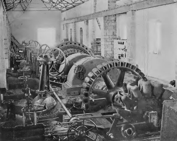
| In the Power House of the Guanajuato Power & Electric Company, Near Zamora. General Electric Generators and Water Wheels Made by the Pelton Water Wheel Co., San Francisco |
The reservoir formed by this dam, when full, will cover an area of three square miles and have a storage capacity of 1,580,000,000 cubic feet. The outlet from the reservoir will be through a tunnel 1550 feet long, driven in the rock to the south of the dam. Water is admitted through screens to two vertical pipes embedded in concrete, each pipe having gates at four different levels, so that the gates will not have to be operated under pressure.
The vertical pipes are joined to horizontal penstocks, 8 feet in diameter and 3/8-inch thick, which pass through the tunnel, the latter being subsequently filled with masonry. The penstocks, after they leave the tunnel, are reduced to a diameter of 7 feet and are carried down stream a distance of 2800 feet, 900 feet of which are through tunnels. At this point, under a head of 180 feet, the penstocks are joined to a receiver, 22 feet long and 7 feet in diameter, from which six smaller pipes conduct the water to the power house. All pipes are connected to the receiver through gate valves, and, in addition, a valve in the center of the receiver permits the two halves of the system to be separated from each other, so that either half can be shut down without interfering with the other.
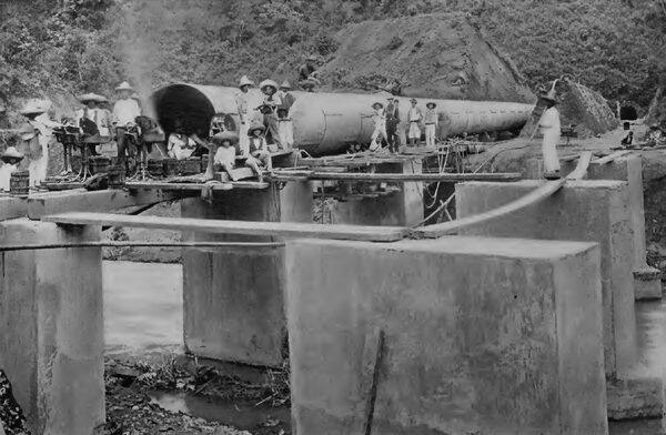
The pipes from the receiver are carried down to the power house, a distance of 2300 feet, 1900 feet of which are through two parallel tunnels constructed at an angle of 41 degrees from the horizontal. There are three pipes in each tunnel supported on concrete with anchorages and expansion joints. These pipes are seamless steel tubes with flanges, each piece being forged complete from one piece of sheet steel. Before the flanges are hammered out, two cast-steel clamping rings are slipped on each 30-foot section of pipe. The outside diameter of the tubes is 30-5/8 inches throughout the entire length of the line. The internal diameter of the tubes is less at the lower end than at the upper on account of the pipe's greater thickness, which varies from 0.4 to 0.95 of an inch, the minimum diameter being 29 inches.
The static head at the lower end of the 30-inch pipe, with the reservoir full, is 1430 feet, which is reduced to 1300 feet when the reservoir is empty and the friction loss is allowed for. A vertical relief pipe, 240 feet high and 20 inches in diameter, is connected to the upper end of each penstock. Each section of tube before being shipped from the works of the manufacturer in Germany, was subjected to a hydrostatic test of twice the maximum pressure to which it will be subjected in service. This pipe is stronger and more reliable than one built up of plates and flanges riveted together, such as is commonly used, and the smooth interior will materially reduce the loss of head due to friction.
The power house is located in the Necaxa canyon a short distance be- low the 750-foot waterfall. It will have a rated output of 30,000 KW, or 40,000 H. P., and a maximum capacity of 50,000 H. P. There will be six main water-wheel units, each capable of delivering 8200 H. P. They are of the impulse type built by Escher, Wyss & Cie, of Zurich, Switzerland, and are of 100 inches pitch diameter, running at 300 revolutions per minute. Each has two 44-inch square regulating nozzles fixed on opposite sides of the wheel, but joined together so that they are opened and closed simultaneously.
A by-pass valve is provided at the end of the pipe line which feeds each unit and is mechanically connected to the nozzles, so that when one opens the other closes, keeping the flow of water in the pipe constant. This is necessary to avoid rams which might prove disastrous with such a high head and long penstock.
A vertical shaft, 14 inches in diameter, carries both the field of the generator and the water wheel. The weight is supported by a thrust bearing, 30 inches in diameter, under which oil is forced at a pressure of 150 pounds per square inch by a pump driven by the main water wheel. This construction has many marked advantages over impulse water wheels heretofore built with a horizontal shaft and a single deflecting nozzle. The double nozzle reduces" the size of both the jet and the bucket, and permits the use of a smaller diameter of water wheel and a higher speed of rotation without sacrifice of efficiency. The nozzle and by-pass are much more easily operated and possess the other good features of a deflecting nozzle. As the nozzles are set in opposition to each other there is no thrust on the steady bearings, and no weight is carried by the latter, so that they need be only a fraction of the size required for a horizontal shaft. The diameter and length of the shaft itself can also be much reduced. The oil thrust bearing is a very simple and reliable de- vice which operates with a minimum of attention.
The amount of water supplied to each wheel and the maximum power can be adjusted at the governor so that water will not be wasted un- necessarily, and the by-pass is also arranged so that, if desired, it can be adjusted to close slowly after opening, a feature which may be desirable with fairly steady loads.
Each unit is equipped with a 28- inch diameter gate valve and a governor of the Escher-Wyss type, both operated by hydraulic power. The six 5000-KW alternators direct connected to the water wheels, running at 300 revolutions per minute were furnished by the Siemens-Schuckert Werke, of Berlin. They are of the revolving field type and generate three-phase current at a periodicity of 50 cycles, and a potential of 4000 volts. Two of the alternators are equipped with 60-KW, directed-connected, 125-volt exciters, but in ordinary operation exciting current will be obtained from two 250-KW, 125-volt generators driven by induction motors wound for 4000 volts. Motor-generator sets are employed, because with small wheels the small nozzles are constantly stopped up by materials floating in the water.
The low-potential current from the generators is raised to high potential by five banks of oil transformers, each bank consisting of three 2000- KW units which can deliver power at 40,000, 50,000 or 60,000 volts to the transmission circuits. The transformers are each placed in a closed fireproof compartment, with steel bulkheads separating them from the generator room, on account of the large quantity of oil used to insulate them. The heat generated, due to the losses in the iron and copper, is carried away by copper cooling coils in the transformer cases, through which water is constantly circulated by motor-driven pumps.
The wiring consists either of cables in conduits or of bare wires in brick and concrete compartments, so that the damage from an arc is limited and cannot injure adjacent circuits. This is particularly important in laying out the 60,000-volt circuits, a substantial wall isolating every wire, switch or lightning arrester. The main switches are all of the oil type controlled electrically from a distance, and any switch will open instantaneously a short circuit of the entire power system. They are also equipped with disconnecting air switches so that they can be cut off from the system for repair and inspection. The high-tension wiring and the lightning arresters are all in a room by themselves behind the transformer pockets.
The oil switches are on the gallery above, with the controlling switch- board in the centre, where the operator can obtain an unobstructed view of the machinery in all parts of the building. The small controlling switches for the large oil switches are, with the miniature lamps which indicate their position, mounted on a benchboard with dummy bus-bars to form a wiring diagram so that the attendant can always see how the apparatus is connected and thus avoid mistakes.
On vertical panels above the bench- board are the indicating instruments which show at any instant the speed, potential and power at which the plant is operating. These instruments are also so placed with relation to the dummy busses and operating switches that the operator cannot become con- fused. At the back of the board are the registering instruments which make a record of the pressure and output of the plant. The switchboard forms a room, with the instruments and controlling devices on the out- side, and doors at the ends to give access to the inside. The transformers and switchboard were furnished by the General Electric Company, of Schenectady, N. Y.
The power house is a substantial steel and masonry building, with concrete and cement roofs, floors and partitions, in which no combustible material of any kind is employed. All the machinery is placed where it can be readily handled by a 50-ton travelling crane. At one end are storerooms for supply and repair parts, and a machine shop equipped with all tools necessary to maintain the apparatus. The building is 235 feet long, 88 feet wide and 60 feet high.
| |||
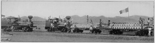
| Rolling Stock of the Mexican Light & Power Co. the Locomotives Are From the Works of the H. K. Porter Co., of Pittsburgh, and the Lima Machine Works, of Lima, Ohio, U. S. A. |
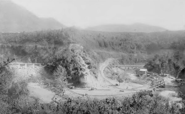
The Necaxa plant is located in one of the most inaccessible parts of the State of Puebla, and for its construction it was necessary to build 30 miles of railroad, besides many miles of roads and trails. The material and machinery for the power house had to be lowered down cliffs and steep inclines by cableways for a vertical distance of 1500 feet, and nearly all the apparatus had to be transported over 4000 miles from Europe and the United States. A temporary plant, consisting of two Pelton water wheels driving air compressors and a 500- volt continuous current generator for operating the hoisting, pumping and other construction machinery, and lighting the work at night, was installed beneath the first fall at Necaxa.
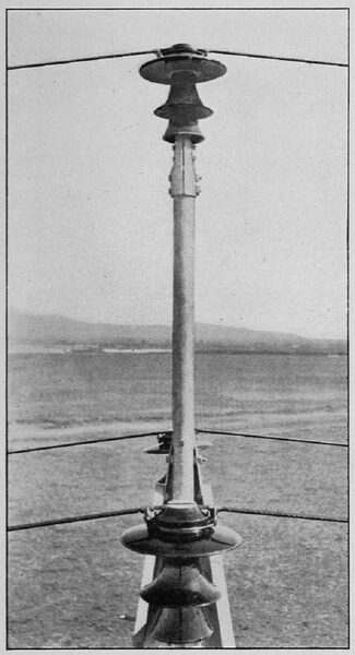
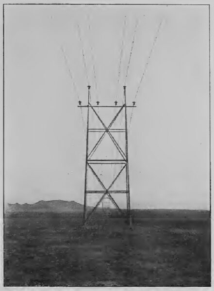
There are four electric power transmission circuits and two tower lines from the power house to the City of Mexico, and two circuits from the City of Mexico to El Oro. They are carried by steel towers, on each of which are two circuits of 168,000- circular mils copper cable, equivalent to Xo. 000 B. &. S. wire, supported on 14-inch diameter porcelain insulators. The towers for the transmission line are built up of steel angles with all parts heavily galvanized and with 3-inch x 3-1/4-inch corner posts spaced 16 feet apart across the line and 12 feet along the line. They are 50 feet high over all, the feet being set 5 feet in the ground. The six cables are supported 40 and 46 feet above the ground, the conductors forming two equilateral triangles with 6-foot sides. The towers will stand a horizontal side strain of 1650 pounds at each insulator pin, or 10,000 pounds altogether. The standard distance between them is 500 feet, but spans up to 1200 feet are made by al- lowing additional sag and employing special structures.
The insulators are made in three parts cemented together on the ground in Mexico. Each part is tested be- fore shipment by subjecting them while wet to a test potential of 60,000 volts. After being assembled they are tested with a potential of 120,000 volts. The insulator pins are 15 inches long and made of 2-inch steel pipe set in drop-forged sockets, which in turn are mounted on a 4- inch pipe cross-arm for the lower conductors, and a 3-inch pipe extension for the upper. They are set into the insulators with Portland cement.
| |||
| Insulators Used by the Mexican Light & Power Co., Made by the R. Thomas & Sons Co., East Liverpool, Ohio |
| |||
| A Tower on the Line of the Mexican Light & Power Co., Made by the Riter-Conley Mfg. Co., Pittsburgh, Pa. |
The conductors are six-strand cop- per cables, -J-inch in diameter, with hemp centres, and have a strength of 60,000 pounds and an elastic limit of 40,000 pounds per square inch. The cable is shipped in lengths of 3000 feet, and joints are made with an 18- inch twisted copper sleeve. The stress on the cables and supporting structures is figured by assuming a wind velocity of 100 miles an hour and allowing a stress in the materials of one-half the elastic limit. The cables are attached to the insulators by clamps, no tie wires being employed. Telephone circuits of No. 10 copper wire are erected on each of the tower lines and are placed 10 feet below the high-potential cables.
The distance from Necaxa to Mexico is 96 miles, and from Mexico to El Oro 75 miles. The total length will therefore be 171 miles, making it the longest commercial power trans- mission yet constructed. There will be 1602 miles of cable and 534 miles of circuit in the high-potential system. The loss in the transmission circuits between Necaxa and Mexico will be 8 per cent, at full load, with 100 per cent, power-factor at 60,000 volts, so that the entire power can be delivered over two of the four circuits, or one-half the transmission system, with only 16 per cent loss, should the other half be disabled. The loss in transmission from Mexico to El Oro is but 5 per cent.
| |||
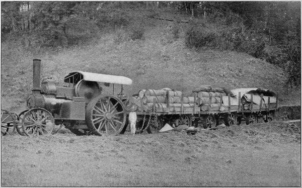
| Hauling A 10-Ton Load of Cement by A John Fowler & Co., Ltd., Leeds, England, Traction Engine to the Site of the Power House of the Mexican Light & Power Company. |
The circuit breakers at Necaxa, Mexico and El Oro are arranged to automatically cut out any transmission circuit which becomes damaged without any interruption in the service. The sub-station buildings in the cities of Mexico and El Oro follow in general the design adopted for the power house. In Mexico there are twelve 1800-KW oil transformers in separate fireproof compartments covered by a travelling crane. The switches and wiring are in separate cells and every precaution has been taken to isolate all parts from each other. In addition to the high-tension apparatus, an extensive low-potential feeder system for the city distribution is provided for in the switch- board. The step-down transformers are arranged to furnish current at either 1500, 3000 or 6000 volts, as may be required.
| |||
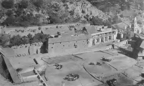
| Patio Process in the Hacienda De Beneficio of the Rio Del Monte Mines, Pachuca. One of the Consumers of Necaxa Electric Power |
The building is 203 feet long and 65 feet wide, and is located adjacent to the company's steam station, originally built by the Siemens-Halske Company. This steam plant now supplies the public lighting of the city and much private lighting and power. In it are installed six 1200- H. P., triple-expansion, condensing engines, running at 120 revolutions per minute, direct connected to 50-cycle, 1 500- volt, three-phase alternators. Four 1000-H. P. Curtis steam turbines running at 1500 revolutions per minute are now being erected in advance of the completion of the water power installation to take care of the rapidly increasing business. Later, this station will be kept as a reserve, although it now seems probable that steam will be required even after the water-power plant is in operation, as practically all the power from the first Necaxa development has already been sold.
At El Oro, a sub-station, 115 feet long, and 59 feet wide has been erected. This is similar to the one in Mexico, and the seven 1800-KW step-down transformers installed there are duplicates of those in the latter city.
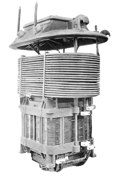 |
| One of the 60,000-Volt Transformers Built for the Mexican Light & Power Company by the General Electric Co., of Schenectady, New York |
The distribution to the gold mines of the El Oro and Tlalpujuhua districts will be at 3000 and 6000 volts. The mines at Tlalpujuhua were first worked three hundred years ago by the Spaniards, who are credited by tradition with having taken enormous quantities of silver from them. That gold existed in the neighboring town of El Oro was known for a century, but it was not until comparatively recently that the cyanide process made it possible to recover the metal from the ores. The great success of the El Oro Mining & Railway, the Esperanza and the Dos Estrellas Companies, has brought the camp into prominence, and many other properties are now being actively developed. Enormous bodies of ore, the veins in places being 200 feet thick, have already been opened up over a wide extent of territory, and El Oro promises to rival, if it does not surpass, the Rand in South Africa, as the world's greatest producer of gold. The mines must, how- ever, be worked on a large scale to be profitable, and the introduction of cheap power has greatly stimulated the activities of the whole region.
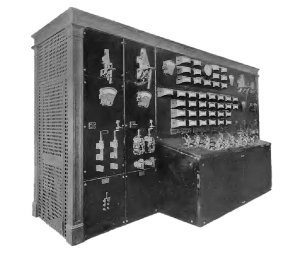 |
| Switchboard in the Power House of the Mexican Light and Power Co., Made by the General Electric Company, Schenectady, New York |
The Necaxa plant has been de- signed with ample reserve power so that the failure of no single piece of apparatus or combination of accidents ever will be likely to cripple the plant. The pipe lines will be in duplicate, reserve units of each kind of hydraulic and electric machinery will be installed, and the transmission lines will have double and quadruple circuits. The buildings, transmission towers and other structures are of permanent and reliable character. Mexico is generally admitted to be the best lighted city on the American Continent, and it is expected that the same high standard of service will be maintained after water power has re- placed steam.
