[Trade Journal]
Publication: Electrical World and Engineer
New York, NY, United States
p. 609
Electric Operations About Massena.
SAINT LAWRENCE COUNTY, New York, the largest in the State, is second only to Niagara in its Water power resources, and probably leads all others in the extent of its mineral deposits. Along the northern boundary of this county the St. Lawrence River flows for 73 miles, passing down Galaps, Du Plats and Long and Little Sault Rapids in its course. These last named rapids represent a fall of nearly 50 ft. in the river along so miles of its course, which could be developed, but by a curious geographic formation it is practicable to utilize nearly all of this fall by discharging water from the St. Lawrence into La Grasse River through a canal about three miles long. Massena is the site of an electric power plant of 20,050 kw capacity, operated with water from such a canal, as has already been described in our columns.
This interesting plant is owned by the St. Lawrence River Power Company, which has kindly made it possible to present here some facts as to its recent extensions and operations. As the plant is located more than a hundred miles from any of the larger cities of the State, and is in the midst of a territory rich in natural resources, the company has chosen to build up a manufacturing center about it, and to supply energy at attractive rates to industries only a few miles distant, rather than to undertake long transmissions of power. Some of the reasons for this policy may be found in the fact that St. Lawrence County offers an attractive field for the manufacture of paper from wood pulp, and contains large deposits of magnetic and hematite iron ore, and of white and blue marble. In accord with the policy just noted, nearly one-half of the present capacity of the electric station is devoted exclusively to the development of energy for the nearby works of the Pittsburg Reduction Company. Four Bullock generators each rated at 2,200 kw and 500 volts, direct current, supply, energy for the company just named, and are kept in operation 24 hours per day and seven days per week with very short intermissions for inspection and repairs. Each pair of these generators is direct-connected to the shaft of a single set of horizontal turbine water wheels, as indicated in Fig. 1.
| |||
| Fig. 1. - Interior of Power House, Showing Aluminum Conductor Under Gallery. |
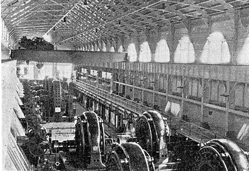
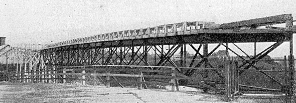
The output of 8,800 kw from the four generators is transmitted from the water power station to the works of the Pittsburg Reduction Company over conductors that have a single length of about 1,500 ft., and are probably among the largest in the world (see Fig. 2). Each side of the two-wire, 500-volt circuit that carries this current of 17,600 amp. is composed of a number of large flat bars of aluminum until a point a little outside of the power house is reached, and then it changes to 25o round aluminum wires, each having a diameter of 3/8 in. For the support of the two conductors like that just described there are two parallel pole lines with cross timbers between opposite poles, and the aluminum conductors lie directly on the wood at every support. An examination at one or two points failed to show any signs of charring in the wood next to the aluminum wires, and it was stated that no trouble had developed from this cause.
| |||
| Fig. 2. - Aluminum Line to Pittsburg Reduction Co. |
In the works of the Pittsburg Reduction Company the greater part of the energy represented by the 500-volt current is used in the production of aluminum, but quite a portion is consumed as power in the wire-drawing mill. Though aluminum is produced at other points by the Pittsburg Reduction Company, it is said that all of the aluminum wire which is made in the United States is drawn at the Massena plant.
Another important manufacturing industry located near the power plant is that of the Indestructible Fibre Company, which uses eleven motors that aggregate 314 hp, and operate at 440 volts. The Massena Mineral Filler Company uses one motor rated at 1,000 hp and 2,080 volts, and the Remington-Martin Paper Company has a motor of like capacity and voltage. One motor of 20 and one of 40 hp operates the plant of the Simpson-McIntyre Co., and the Massena Machine Works has a to-hp motor. The St. Lawrence County Electric & Water Company, which distributes electric light in Massena, uses two 25-hp motors to drive machinery in its station.
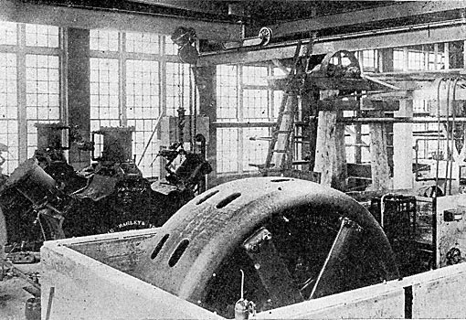
The most interesting of these power installations is that of the Remington-Martin Paper Company, which is at Norfolk, about 12 miles from the water power plant. At the mills of the Remington Company a 1,000-hp motor is devoted to the unusual if not unique work of grinding logs into pulp. This class of work is one of the heaviest done about a paper mill and is most commonly carried on with direct mechanical connection between the water wheels and pulp grinders. In the mill of the Remington Company, however, the pulp grinders are direct-connected to an induction motor that operates at 2,080 volts, 25 cycles, three-phase and 214 r.p.m. (see Fig. 3). This motor, which is of the General Electric make, drives four wood pulp grinders, two being connected at each end of its shaft. About this motor there is a housing with removable top. This motor is started with an external resistance connected through collector rings on the rotor, and a hand wheel on the motor short-circuits the secondary after the controller is cut out. The grinding of pulp with electric power has been found to be so satisfactory that the paper company is about to adopt it in another mill. It may be noted here that the satisfactory application of electric power to the grinding of wood pulp will result in the location of mills at points where they have not heretofore been thought practicable, because of the lack of cheap power, and will thus materially increase the amount of electric transmission.
| |||
| Fig. 3. - Induction Motor at Norfolk Mill. |
In order to economically transmit the energy for this 1,000-hp motor it was necessary to raise the pressure of 2,200 volts generated at the former place to some higher value, and 22,000 volts was selected for the purpose. The 2,200-volt overhead lines run from the generating station to a transformer house a few hundred feet distant, and there connect with three oil-insulated, self-cooling transformers of the Westinghouse make. Each transformer is rated at 375 kw and operates with 1,900 to 2,200 volts in the primary and with 19,000 to 22,000 volts in the secondary windings.
Near the plant of the Remington Paper Company in Norfolk there is a terminal house in which is placed a similar group of transformers which reduce the line pressure to about 2,080 volts for the motor. A single three-phase circuit of aluminum connects the transformers in these terminal houses at opposite ends of the transmission line, which is 11.73 miles long. Each conductor of this circuit is made up of seven aluminum wires each 0.099 in. in diameter, so that the cable has approximately the cross-section of a No. 2 B. & S. gauge wire. These three power cables enter the transformer houses through circular openings fully 12 in. in diameter, which are protected from the weather by a hood in each case. Between the centers of adjacent circular openings the distance is about 4 ft., and this is the standard distance between the three cables along the pole line.
The pole line is built mainly of Michigan cedar poles, each 30 ft. long and having a 6-in. top. Each pole carries one two-wire cross arm for the power cables and the third cable is mounted at the top. At railway and river crossings special timber structures or long poles take the place of the ones of the regular size. Where the transmission line crosses the Massena Terminal Railway a double-pole structure is used on the one side and a tall pole with a special form of guard irons beneath the conductors on the other side. These guard irons are secured at either end of a horizontal bar that is attached to the pole beneath the conductors and parallel with them. Each guard iron resembles a cross arm with its ends turned up, and it is intended to catch any cable that falls from its insulator. In crossing La Grasse River the aluminum cables make a span of 377 ft. between timber structures, and with the temperature at 28° C. the sag of each cable is so ft. At the crossing of the Raquette River the span is 555 ft. between wooden structures, but in this case the aluminum cables are supported by two steel cables, each of which is secured to timber struts and passes over wooden saddles on the fixtures that support the power conductors, as shown in Fig. 4.
| |||
| Fig. 4. - Raquette River Span on Norfolk Line. |
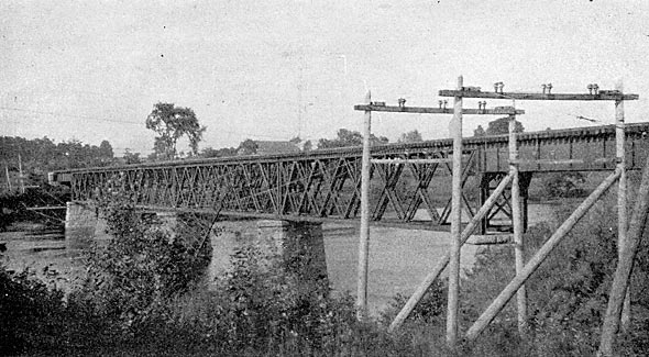
Each steel cable contains seven strands of wire o.160 in. in diameter, has a weight of 0.52 pound per foot, an ultimate strength of 9,800 pounds, and a sag of 22 ft. between supports at 26° C. The pair of steel cables carry four cross arms between supports and the aluminum cables are attached to regular line insulators on these cross arms. %%One-piece porcelain insulators, which are used to support the 22,000-volt circuit, are giving satisfactory results. Each insulator is 5 7/8 in. in height, 7 in. in greatest diameter and has a groove 7/8 in. wide for the cable at its top (see Fig. 5). Of the two petticoats on each insulator, the inner extends about 2 7/8 in. below the outer and is 3 3/4 in. in diameter. The depth of pin hole is. 1 7/8 in., and from the top of the pin hole to the top of the insulator the distance through porcelain is 1 5/8 in. At each insulator the aluminum cable is mounted in the top groove and is held by a solid aluminum tie wire 30 in. long of No. 2 B. & S. gauge.
 |
| Fig. 5. - Diagram of Insulator. |
These facts as to electric operations about Massena are presented through the kindness of Mr. E. B. Bumsted, general manager of the St. Lawrence River Power Company; of Mr. R. D. Pierce, and of Mr. Irving A. Taylor, general superintendent.
