[Trade Journal]
Publication: The Journal of Electricity, Power and Gas
San Francisco, CA, United States
p. 80-83, col. 1-2
THOMAS HIGH TRANSMISSION INSULATORS.
In the development of high-tension transmission lines and the work that has been accomplished in this direction within ten years, no one item has been a greater factor than the high tension insulator.
About 1896 the R. Thomas & Sons Co. of East Liverpool and Lisbon, Ohio, who have been engaged in the manufacture of electrical porcelain for low tension work for many years, began investigation of the question of manufacturing a high-grade porcelain insulator for transmission work. Before attempting to put any of these insulators on the market they thoroughly investigated the situation to ascertain what would be expected of the insulators and learned that the conditions would be most severe, both mechanically and electrically. While such porcelain as they had made in the years past was recognized as standard quality, the process of manufacturing for high tension work was an entirely new problem. They therefore began, and carried on, for upwards of eighteen months, experimental work, to secure a body and glaze that would bring about the result desired, namely, a highly vitrified insulator, homogeneous and capable of standing great electrical strains, and, at the same time, show unusual mechanical strain. Their efforts were in the direction of testing out all known clays, both domestic and foreign, and after a long series of experiments, they found that the high-grade foreign China clays gave the best results. In 1897 they developed one or two sizes of insulators not larger than 6 inches in diameter, and these were placed and operated successfully on lines ranging in voltage from 10,000 to 22,500, and so far as the company knows are operating successfully at the present time. The designs then brought out, however, were found later to be entirely inadequate for higher voltages, as all engineers, as well as manufacturers, seemingly had in view, in the early stages of this development, insulators with great creeping surface, failing at the time to take into consideration arcing distance or air space. However, all of this work led up to a very much greater development, and in 1903, the Thomas people issued their first high voltage catalogue covering about thirty designs for voltages ranging from 5,000 to 60,000, although at that time the 60,000 volt lines were not numerous. The requirements since then have created a demand for insulators capable of carrying 100,000 volts for long distance, and commercial insulators to supply this demand have been furnished. At the same time experimental work is being done on insulators capable of higher voltageseven up to 150,000 volts. The great progress which has been made in this line is shown by the fact that the Thomas catalogue of 1903 included only about thirty designs, while at the present time this company have on the market over one hundred distinct types and practically every type has been placed in service.
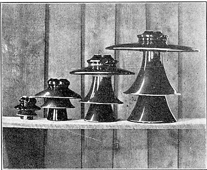
| |||
| The Four Insulators Shown Above Range in Size From 5 to 21 Inches in Diameter and From 5 1/8 to 18 5/8 Inches High. |
To go more fully into the subject of manufacture, we believe that the first insulators made for transmission lines were of a solid piece of clay, while the R. Thomas & Sons Co., in their early experimental stages, worked along the lines of making the insulators in separate shells. It is a fact well known in the art of pottery that a thin piece of clay can be moulded and vitrified more satisfactorily and more free from cracks and flaws than a thick piece, and it was for this reason that they worked along these lines. The firing of these shells is a very important factor and detailed uniformity and proper thicknesses were worked out first in order that they would properly withstand the firing, maintain their shape, and retain the proper and uniform thickness to give mechanical strength.
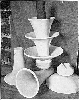
| |||
| Separate Shells of Insulators Ready for Glazing. |
Another important feature that enters into the manufacture of high voltage insulators, is the thorough electrical testing of them in order that all flaws and imperfections may be discovered before they are placed in service. In the early stages of manufacturing, The Thomas Company installed a testing set with a capacity of 60,000 volts. This, however, was found inadequate within a year, and new testing apparatus was installed capable of from 120,000 to 150,000 volts and of about 40 kilowatt capacity. Two years later, the business had grown, and the requirements in the way of tests had became so much greater that it was found necessary to install still a larger testing apparatus, and they, therefore, placed in operation a 200 kilowatt capacity set, capable of from 200,000 to 250,000 volts. With this testing plant, some other interesting features have been brought out, particularly in placing the insulators under severe conditions, such as heavy rain storm tests, etc., to ascertain at what point various types of insulators would arc over or the current jump around from the wire to the supporting pin.
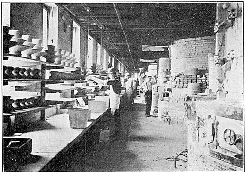
| |||
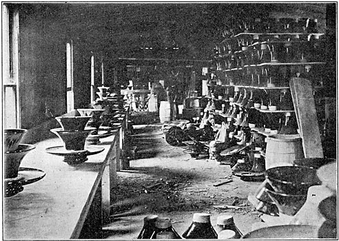
| A Corner in the Kiln Sheds. |
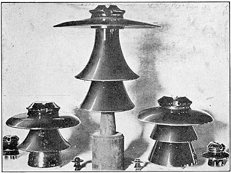
| |||
| From the Baby to the Giant. Showing Range of Sizes Manufactured by the R. Thomas & Sons Company. |
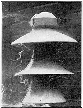
In cut No. 1 is shown an insulator designed by Mr. R. D. Mershon, for use on one of the lines for which he was consulting engineer. This insulator, as shown, was placed in position on a metal pin with one wire through the top groove and around tie wire groove and the other wire fastened to a metal pin at the bottom of the lower petticoat with approximately 3/4-in. precipitation of rain on the insulator; a voltage of 100,000 was turned on it and this gradually stepped up to 130,000 volts, when the current arced around from wire to wire, but no injury was done to the insulator.
| |||
| Cut No. 1. Undergoing A Precipitation Test of ¾-Inch Per Minute, at Voltage 130,000. |
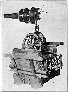
This same insulator was then placed in position as shown by cut No. 2 on a large metal pin for mechanical test. Heavy pieces of casting were used for this test and smaller pieces of metal added until the weight had reached 4,225 pounds when indications were that the pin would soon bend. While this weight was being sustained by the insulator, as shown by the photograph, current of 160,000 volts was applied. This was for the purpose of ascertaining if any electrical defect was produced by placing the insulator under severe mechanical stress. Nothing occurred to affect the insulator in any manner whatever, although the pin gradually bent until the castings touched the floor at this weight.
| |||
| Cut No. 2. - Mechanical Test. |
This same insulator was then placed in the testing bath and current turned on and raised until it reached about 186,000 volts, when it arced over; this test could be carried no further, as it had reached the arcing point.
None of the tests above described affected the insulator in any way.
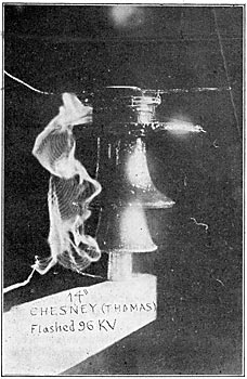
Cut No. 3 shows an insulator designed for and put in use on the Necaxa plant of Mexico, of which Dr. F. S. Pearson is the consulting engineer. This insulator was put under rain test of three-quarter inch precipitation per minute, and for this test, we are indebted to Mr. C. C. Chesney of the Stanley G. I. Company of Pittsfield, Mass. The test was made in a dark room, and after the insulator had been thoroughly wet with the rain sprayed from various angles a current was turned on and voltage raised until it reached 96,000 volts, when it flashed around from wire to wire.
| |||
| Cut No. 3. Undergoing A Precipitation Test of ¾-Inch Per Minute, at Voltage of 96,000. |
This insulator also has been given a mechanical test of about 3,000 pounds.
Another very interesting test given on the insulator, shown by cut No. 3 was the following:
1st. Clean and dry;
2nd. With water sprayed on at an angle of 30 to 40 degrees;
3rd. With insulator enveloped in steam from boiler;
4th. With insulator enveloped by steam from salt water.
In all of these tests, the cross-arm was 4 3/4 inches below the bottom petticoat.
Test No. 1. Insulator was put in a position approximating line conditions. Under these conditions, at about 140,000 volts, there was a noticeable play of "static" about the upper part of the head. The voltage was then raised to 180,000, which was as high as they cared to go with the apparatus at hand. Although the insulator at 180,000 volts did not arc over strongly, there was a spitting or crackling spark now and then which appeared to extend from the line wire to the iron pin following the outline of the insulator in its course. Although the voltage could not be raised, it appeared that the insulator was about on the point of arcing over.
Test No. 2. In this test, the Water was forced through a nozzle and spread out over the entire insulator, striking it with considerable force at an angle of about thirty-five or forty degrees. It was hardly fine enough to be called a spray and struck the insulator with sufficient force to spatter considerably. Under these conditions, it took 101,000 volts to arc over the insulator.
Test No. 3. In this test, the insulator was in an enclosure about 6x7x8 ft. high. There was a door about 6x3 ft. leading into the testing room from the enclosure. Steam was sent into the enclosure from the boilers in the engine room. While the insulator was fully enveloped by the steam, it was impossible to get it to arc over at 180,000 volts, but on applying voltage to the insulator within a few seconds after the steam was turned off, about 140,000 volts was all that was necessary to arc it over. However, by waiting still longer before applying the voltage, it took about as high a voltage to arc it over as if the insulator were dry. In about five minutes after the steam was turned off, 180,000 volts was applied to the insulator without arcing it over. At this voltage and under these conditions, there was a play of static all over the insulator from top to bottom. With the insulator enveloped in steam, there was very much crackling at 170,000 volts, but it did not arc over at 180,000 volts. It should be noted here that although the insulator was not visible on account of the steam surrounding it when there was no voltage applied, it could be very clearly seen when the high voltage was applied. This high voltage seemed to clear the fog around the insulator. During this test, the insulator was slightly warm.
Test No. 4. In this test, with the salt fog, the steam was not forced into the enclosure under pressure as in the previous test. About three feet below the insulator and a little to one side, was placed a galvanized iron wash tub containing about five inches of water and more salt than the water would dissolve. Under this tub was placed a large gas burner in order to boil the water. After the water boiled vigorously for about twenty minutes, the test was made. Owing, probably, to openings around the side of the enclosure, it would not fill up with steam as much as was desired, even when the door was closed. However, the steam floated up around the insulator so that salt was easily detected by placing one's tongue to the insulator before the current was turned on. Around the vertical part of the head of the insulator there was a film of condensed moisture. So much heat was necessary in order to boil the water that the insulator was heated up quite noticeably during the test. Under these conditions, the insulator arced over at about 180,00o volts. This test was conducted in the presence of Mr. R. H. Dillon, representative of the Mexican Light & Power Company, New York City.
| |||
| Cut No. 4. - Mechanical Test. |
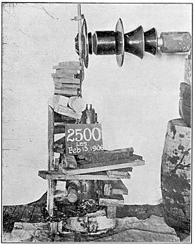
In the demand which seems to be growing for insulators for extreme high voltages, and in the direction of producing an insulator for working voltage of 125,000 to 150,000, the R. Thomas & Sons Company, as practical potters, realize that it is impracticable to extend the diameter of insulators to much greater extent than eighteen or twenty inches, owing to the trouble given in the drying and firing process in keeping them straight. They therefore worked out a new insulator which is shown in Cut 4. When first presented to some of the leading engineers they were inclined to question its mechanical strength. Therefore, as shown by Cut No. 4, a mechanical test was made, using weights as described in Cut No. 2, and after placing 2,500 pounds on the insulator the pin bent to such an extent that they could go to no higher weight.
Later a mechanical test was made in the presence of Mr. F. O. Blackwell and Mr. Cooper, and carried to a point of 3,500 pounds, under which weight the pin bent so much that it came in contact with the center. As yet no accurate data has been secured as to the electrical capabilities of this insulator, although some very high tests have been made on it; but, through the courtesy of Mr. R. D. Rushmore of the General Electric Co., of Schenectady, an elaborate test will be made with their 500,000-volt apparatus, result of which will be given later; preliminary tests made by the manufacturer satisfy them of their ability to produce an insulator for any voltage that may be required.
| |||
| Cut No. 5. - Tested Insulators Ready for Packing. |
One point in connection with the Thomas high-transmission insulators which deserves special attention is the perfectly smooth, bright glaze. Electrical engineers all agree that this is a very strong feature and tests have shown that, beyond all contradiction, this glaze is absolutely free of leads or any oxide which would prove a detriment in electrical work. It has also been agreed by electrical engineers that the requirements of high-transmission insulation can only be produced by practical potters of unquestioned experience and ability, and when it is considered that the Thomas family have for three generations devoted their entire time to this industry it is safe to assume they are particularly well qualified for the work. They have been particularly fortunate in this development in receiving the sincere co-operation of leading electrical engineers, both in this country and Canada, and it is largely due to this co-operation that they have been so successful in placing upon the market, not only numerous designs, but designs which have been proven successful under trying conditions.
