[Trade Journal]
Publication: Elektrotechnische Zeitschrift
Wuppertal, Germany
p. 348-349, col. 2, 1-3
Electrical line systems and accessories.
High-voltage insulator bells.
[Lecture by V.G. Converse. "Transactions of the International Electrical Congress, St. Louis 1904, Vol. II, p. 348, 16 pages, 12 figures]
14 years ago, 3000 V was considered a very high voltage. The development of high-voltage bells was naturally initially based on the experience with the older low-current bells, as was generally the case in line construction. Glass or porcelain, or both at the same time, were considered as insulating materials. The economic success of high-voltage power transmission remained doubtful until recent years. Every engineer tried to solve these questions and countless bell shapes of various colors were created on wooden or iron bolts, with all kinds of safety bindings for the wire. The double glass bell with a diameter of 76 mm was used successfully in the first plant for 3000 V in the United States in 1890. In Europe, the oil insulator with a bent edge to form an inner shell or with a separate liquid bottom shell appeared. This latter form was intended to be used in the 10,000 V plant at Ponoma and San Bernardino in California, but the shell soon proved to be useless. Triple bells made of glass or porcelain appeared. The number of mantle folds or shallow grooves in the one-piece bell body rose to 4 or 5. By 1895, in Switzerland, the power transmission plant in Hochfelden-Oerlikon had reached 13,000 V, and in 1897, in the United States, up to 16,000 V - although this was encouraged by the famous Frankfurt-Lauffen experimental plant with 30,000 V in 1891. Around 1897, it became clear that the reliable electrical breakdown resistance was due to the glazed surface of the porcelain bells, not to their mass itself, which led to forms made of multiple, thin-walled shells that were fused together with glass.
 |
| Insulator of the Plant in Provo, Utah. 40,000v. Fig.39. |
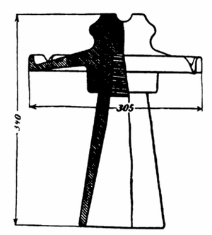 |
| Insulator of the Bay Counties Co. Facility. 60,000v Fig.40. |
In 1898, the first permanent high-voltage system was already in operation at Provo in Utah with 40,000 V. The glass bell used had three external grooves on the head for higher surface resistance (Fig. 39). Around 1900, the Bay Counties and Standard Electric Companies of California required the largest bells to date for 60,000 V, the so-called mushroom shape, with a diameter of 305 mm (Fig. 40). The flat, separate upper part made of porcelain allowed the rainwater to run off over two edge noses on the right and left over the supporting crossbeam, while the lower glass cup part extended over the entire bolt. Originally, both parts were cemented together with sulfur, later with cement.
The forms mentioned do not only represent development stages of newer ones, but they often persist alongside the latter. The usual double bell is still preferred in some places up to 10,000V, while the later forms mentioned all remain until 10,000V satisfy in many ways. Some bells initially hold up quite well, then problems appear, leading to the complete removal of small defects. There are actually situations where only external damage can cause bell defects and the bell molds for 40,000 bells can be considered to have been completely and satisfactorily resolved.
 |
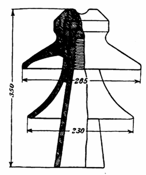
| Insulator of the Plant on the Missouri River, Mont. 55,000v Fig. 41. |
 |
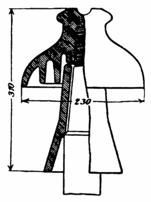
| Insulator of the Shawingen Falls Facility. 50,000 V. Fig. 42. |
Fig. 41 shows a picture of a second glass bell of the Missouri River Power plant in Montana for 55,000 V, which has been in use since 1919. The lower part is to protect the bell. A bell of Shawinigan Falls, Que., for 50, consisting of three bells cemented together with Portland cement, is shown in Fig. 42.
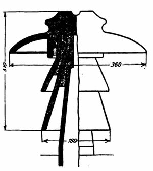 |
| Insulator of the Plant in Guanajuato. 60,000 V. Fig. 43. |
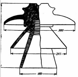 |
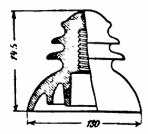
| Insulator for 50,000 to 60,000 V. Fig. 44. |
An advantageous shape (Fig. 43) was used in Guanajuato, Mexico, for 60,000 Vb. It has a diameter of 360 mm and is fixed to a hollow bolt using cement. Some plants with 500 to 60,000 V have dared to use the shape Fig. 44, which exceeds 360 mm in diameter and weight here and there. The insulator bell was developed from 76 mm to 360 mm in diameter and from 1,500 to 2,500 V. 11.5 kg weight, while their costs grew from a few pennies to several marks.
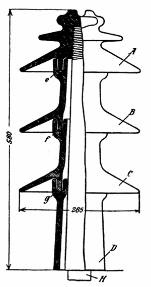 |
| Insulator Shape According to Converse. Fig. 45. |
Will 80,000 V of 500 mm and up to 25 kg be a challenge in the future? The desire to use mast towers with large wire spans has recently led to even more mechanically stronger bells. Whether this will result from achievements in materials not yet developed for this purpose or in the less developed glass bell industry remains to be seen.
The requirements of the high-voltage bells can be summarized as follows:
smaller. In cold regions, larger bells will generally be required than in warmer ones. On the Pacific coast, salty fog forces shapes with a few shallow shells that can be cleaned more frequently. 5. The shape and quality of the bell should correspond to the smallest electrostatic capacity. 6. The heat losses through conduction and dielectric hysteresis should be imperceptible. 7. The mechanical stress caused by wire pulling, during the wiring installation and similar events depends on the respective conditions. The bells are tested in the following way:
1. The inverted insulators are immersed with their heads in acidified water, with which the bolt opening is also filled, so that the test voltage can take effect between them for a few minutes. Defective pieces break through with a screeching noise. Bells made from several special pieces are tested twice. First the individual parts, then the assembled bells.
2. Measuring the surface current is difficult in practice. Any significant discharge is revealed by heating and by the arcing over.
3. Using some bells tested according to 1 and 2 and found to be OK, the intended pin fastening is carried out, the cable is tensioned; the remaining observations are then carried out at the specified operating voltage.
4. The climatic conditions are simulated as far as possible by allowing rain showers to act on the bells at an angle to the horizontal during the test. In order to prevent the increase in the diameter of the bell with increasing voltage, Converse suggests the method shown in Fig. 45. form. A is the top piece screwed onto the wooden bolt, collar C are equal intermediate pieces and D is a lower piece resting on the cross arm that supports collar C. The pits e, f and g accommodate an insulating putty The total height is 580 mm and the diameter is 265 mm. Testing of this form showed arcing between the following points on the insulator and voltages in kilovolts:
Insulator clean and dry: A and D 144,000 V; AB and D 186,000 V; ABC and D 225,000 V. Insulator exposed to rain at an inclination of 450 degrees from the horizontal and a rainfall height of 19 mm in 5 minutes: A and D 118,000 V; AB and D 157,000 V; ABC and D 198,000 V.
There was no putty in the pits and the arc showed no tendency to strike the bolt between the pieces. High voltage keeps all bells, whether porcelain or glass, away from dust through electrical repulsion and from rain through evaporation. In general, the energy loss until the cluster light occurs is very small.
In the discussion of the lecture, Scott says that the costs for the bells are low, despite the fact that they are an essential element of the system. In a large and important American system, for example, they amount to 1.20 to 1.90 M per kilowatt, so that the interest for one year and kilowatt is only 4.25 to 9 Pf. So even a multiple, even tenfold increase in the costs for insulators would hardly be economically viable.
H. and F.
