[Trade Journal]
Publication: Street Railway Journal
New York, NY, United States
vol. 30, no. 1, p. 4-15, col. 1-2
A. C. ELECTRIFICATION ON THE ILLINOIS TRACTION
SYSTEM
BY JOHN R. HEWITT
The Illinois Traction System is, without doubt, one of the largest electric traction interests in the country. It embraces every phase of interurban railroading and is at the present time extending in all directions in an astonishingly rapid manner. We believe that we are correct in stating that all the lines constituting this system were constructed by the Central Illinois Construction Company, and that they are operated by various operating companies which, in their turn, comprise the McKinley Syndicate.
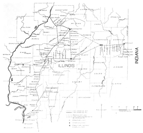 |
| Fig. 1. — the Present and Proposed Lines of the Illinois Traction System |
The object of the present article is to deal with the extensive a. c. single-phase lines recently put into commission, together with those under construction which are to be put into operation in the near future, and to describe the apparatus employed in their operation; but owing to the many features of peculiar interest in this system as a whole, it seems advisable to preface this description with a few general remarks covering the most salient points.
The map published herewith in Fig. 1 will give a general idea of the territory served and the accompanying table will show the names of the different operating companies, the mileage of each line and method of operation, whether a. c. or d. c. At present the total mileage in operation amounts to 381.5 miles, and the proposed lines aggregate approximately 90 miles, making a total of 471.5 miles of road that will be in operation in the near future. Of these, 95 miles are at present operated on, or being equipped for, the a. c. single-phase system.
Besides the roads already mentioned, it has been announced in the daily papers that a road, in connection with the Illinois Traction System, is to be constructed between Bloomington and Chicago, but it is too early to make any definite statements concerning this at the present time. Over and above the operation of these electric roads as outlined above, the Illinois Traction System controls the city street railway lines in numerous cities in the Middle West and provides for other public utilities, such as power and light, in these districts. Some of the towns served in this manner are indicated on the accompanying map, but in this respect the map is incomplete.
| |||
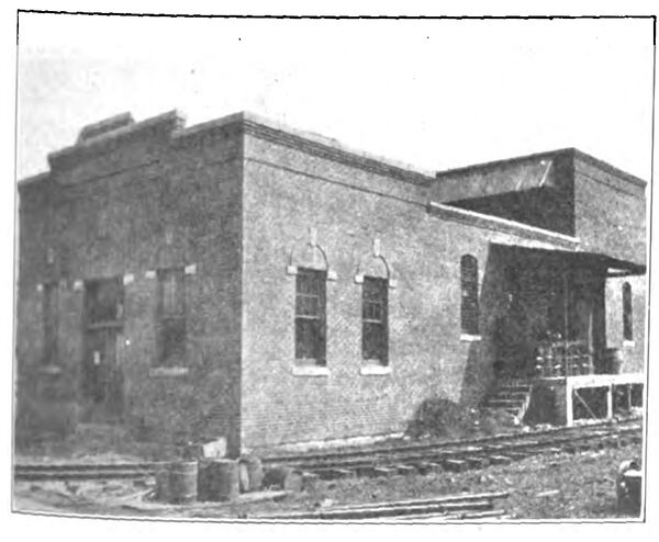
| Fig. 3. — Exterior of Danvers Sub-Station, Freight House and Waiting Room |
To operate this vast system there are at present nine power houses, located, respectively, at Danville, Champaign, Decatur, Bloomington, Peoria, Riverton, Edwardsville, Venice and Jacksonville. Most of these have already been described in the columns of the STREET RAILWAY JOURNAL.
The sub-stations, which are widely distributed over the system, are too numerous to describe in an article of this length, but at the same time it is interesting to note that considerable use is made of portable sub-stations, which can be used with such good advantage on a system of this size to reinforce the power on any portion of the road that is overloaded temporarily from any cause, or to provide power when construction work is being done which would other-wise cripple operation.
As is evident, the equipments are very numerous and comprise cars of many different types and a large variety of electrical apparatus. The cars range from the smaller type of street car to some of the finest specimens of interurban cars to be seen on the continent of America ;prominent among these are the handsome sleeping cars running between St. Louis and Decatur, which have already been fully described.
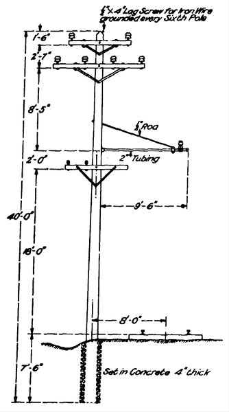 |
| Fig. 2. — Details of High-Tension Transmission Line |
The freight business, in all probability, has reached larger proportions on this system than on any other system of electric roads in the country; two 50-ton. d. c. electric locomotives are in daily operation, and a 40-ton a. c. locomotive will shortly be put into service on the newer sections of the road. Practically all the coal used in the various power houses is hauled over the syndicate's own roads electrically, and a very extensive business is being carried on in handling coal for domestic purposes as well.
Carload lots of cattle and grain are also hauled by the electric locomotives, and a great deal is done in the direction of the express business. The usual load for the electric locomotive varies from ten to twelve loaded cars. To facilitate the handling of such large quantities of freight, belt lines are being built around many of the larger cities ,notably at Springfield and Decatur. There are freight depots in all the towns and cities connected by the various lines.
Confining our attention now to the a. c. system recently put into operation and to those roads about to be converted from d. c. to a. c., the line from Peoria to Bloomington, which is 38 miles in length, is already in daily operation with single-phase current. This section was first operated from terminal to terminal on the new system on Sunday, April 1. The line from Springfield to Lincoln, 30 miles in length, is at the present time in daily operation with direct current, but the catenary line is erected for high-tension a. c. operating and the sub-station buildings are completed, while the apparatus is at present being installed. This section will change from d. c. to a. c. operation in the course of a week or two.
The road from Lincoln to Mackinaw, which will be operated a. c., will be approximately 27 miles. long and is at present under construction.
GENERAL SCHEME OF ELECTRIFICATION
The general scheme of electrification of these roads now operating a. c. and those about to be put in operation during the next few months is as follows:
The power is generated at the new Peoria power house at a pressure of 2300 volts. It is stepped-up to 33,000 volts in the power house and is fed to the transmission line at this pressure. At the sub-stations this potential is reduced to3300 volts for feeding the trolley. There are power houses situated at Bloomington and Decatur, from which it is also proposed to feed the transmission line if occasion demands.
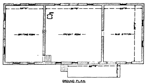 |
| Fig. 4. — Plan of Danvers and Morton Sub-Stations |
To render this description more concise and avoid confusion, the Peoria to Bloomington section will be described in detail as being typical of the a. c. construction and equipment throughout. Special mention will be made where details of other sections differ to any marked degree.
POWER HOUSE
The steam equipment of the new power house, recently erected at East Peoria for supplying energy to the Peoria-Bloomington line, is a red brick structure with a roof of reinforced concrete and concrete floors.
The electrical equipment includes two Curtis turbines, each of a capacity of 2000 kw; these are four-stage condensing units operating with an average vacuum of 29 in. and at a normal speed of 750 r. p. m. The generators them-selves are three-phase, 25-cycle General Electric machines; each has four poles and delivers current at a pressure of 2300 volts.
Two General Electric rotary converters have been installed to supply power for the city service; these are 750-kw, 10-pole, 25-cycle units running at a speed of 300 r. p. m., and supply 1250 amps. at 600 volts.
There are thirteen transformers in all-six 700-kw Westinghouse units wound for 33,000-2300 volts and six 250-kwestinghouse transformers wound for 33,000-430 volts. The thirteenth is a General Electric transformer of 75-kwapacity, and is wound for 33,000-2300-1150 volts. All of these transformers are oil-insulated and water-cooled.
 |
| Fig. 5. — Plan and Elevations of Danvers and Morton Sub-Stations |
Two exciter sets are provided for supplying current to the fields of the main generators; one of these is a turbo exciter set and the other a motor-driven set. The former isa 75-kw, four-pole, horizontal Curtis turbine set, running at 2400 r. p. m., and supplies 600 amps. at 125 volts, while the latter consists of a 100-hp, 25-cycle induction motor direct coupled to a 70-kw generator which has a speed of 500 r. p. m. and supplies 560 amps. at 125 volts.
The other principal items among the auxiliary apparatus are as follows : Two Wheeler condensers of the surface type, two horizontal air pumps by the Wheeler Condenser Company, one circulating pump and two feed-pumps by Dean Brothers; there are also two step bearing and twostep bearing return pumps. The feed-water heaters are of the Cochrane type, manufactured by the Harrison Safety Boiler Works.
The boiler room is equipped with eight Stirling water-tube boilers, each having a capacity of 500 hp and providing steam at a working pressure of 190 lbs. per square inch. These boilers are stoked mechanically by motor-driven chain grates.
This description of the power house is far from complete, as a long and more detailed article will be published in the near future which will deal with the Peoria power house alone, and, therefore, will give fuller particulars.
HIGH-TENSION TRANSMISSION LINE
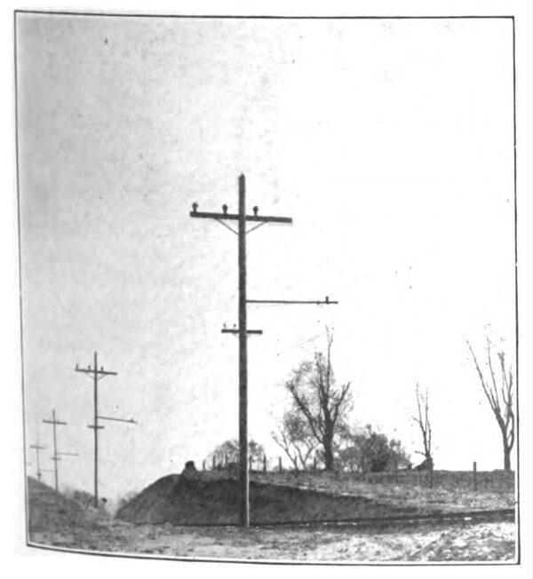
The illustration, Fig. 2, will show the details of the high-tension trans-mission line, and it will be seen that it does duty for supporting the trolley wire. Ultimately the transmission line will be in duplicate, but at present only three wires are strung.
The high-tension voltage is 33,000, three-phase, at 25 cycles per second. The wires are of No. 2 B. & S. hard-drawn copper supported on Locke No. 312 porcelain insulators tested to a pressure of 60,000 volts. The insulators are fixed to truss pins of malleable iron.
The pole line will certainly rank as one of the prettiest pole lines in the country; every pole is wonderfully straight and has the appearance of being turned in a lathe. They are of Spokane cedar, 40 ft. in length, with a diameter of 7 ins. at the top and range from 12 ins. to 14 ins. in diameter at the base. The poles are buried to a depth of 7ft. in the ground, each being planted in cement, and, where the poles were planted on fills before the grading was completed, they are buried in barrels of cement.
The upper cross-arm, which is not at present in place, will carry two insulators, will be 4 ft. in length, and have a section of 3 1/4 ins. x 4 1/2 ins. The lower arm carries four insulators, is 10 ft. long, and has a section of 3 1/4 ins. x 5 3/4 ins. The cross-arm for supporting the telephone insulators is 4 ft. in length. All the cross-arms are stiffened by means of galvanized iron angle braces. The distance from the center of track to the center of poles is 8 ft. The relative height of these cross-arms, the spacing of insulators and other dimensions will readily be seen by reference to the cut, Fig. 2. The poles are spaced 140 ft. apart on straight, level tangent, and at curves and street crossings the spacing is usually reduced to 100 ft., but this distance is varied to suit any special conditions.
| |||
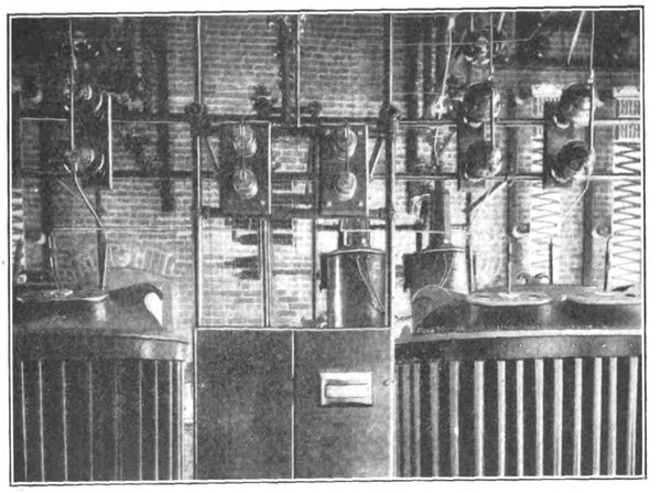
| Fig. 7. — Transformer Switch Compartments, Etc., in the Morton Sub-Station |
An efficient means of protecting the transmission line from damage by lightning is afforded by a No. 6 B. & S. galvanized iron wire strung for the entire length. This wire is grounded at every sixth pole and the ground wire is stapled to the poles at intervals of 3 ft . The wire is attached to each pole by means of a lag screw and two washers, the wire lying between the washers and being tied on either side of the lag screw by means of a length of iron wire which has its ends turned up for a distance of 6 ins.in a horn fashion . This device will add materially to the efficiency of the lightning protection.
SUB-STATIONS
The sub-stations on the Peoria to Bloomington section are located at Danvers and Morton, while the Springfield to Lincoln section is provided with sub-stations at Selby town and Lincoln, and when this line is finished through to Mackinaw additional sub-stations will be built.
The Danvers and Morton sub-stations are identical in all respects. The external view shown in Fig. 3 and the plan in Fig. 4 will give a good idea of their general features.
It will be seen that a waiting room, freight house and sub-station are combined in one building, which, it may be interesting to note, is also a feature of a large number of the sub-stations on the different d. c. lines of the Illinois Traction System. The great advantage in this instance is that the man in charge of the freight house and waiting room can perform all the necessary work in the a. c. sub-station , which requires no attention excepting when the oil switch is thrown by an excessive overload. This arrangement entirely avoids, on the one hand, unnecessary delays when the switch is thrown, or, on the other hand, the expense of keeping at the sub-station an employee who would necessarily be idle for practically the whole time.
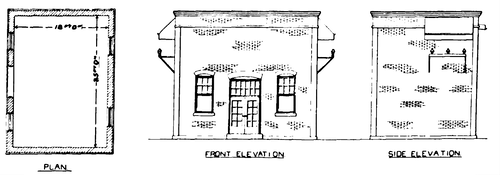
The buildings are of red brick with reinforced concrete ceilings and concrete floors. The dimensions of the sub-stations proper at Danvers and Morton are: Length, 30ft.; breadth, 20 ft., and height, 21.5 ft.; while those at Selbytown and Lincoln, which have no freight house or waiting room attached, are slightly smaller, being 25 ft. in length, 18 ft. in breadth and 21.5 ft. in height. Fig. 5 shows the plan and two elevations of the Selbytown and Lincoln sub-stations.
 |
| Fig. 6. — Wiring Diagram for Single-Phase Sub-Station at Morton and Danvers |
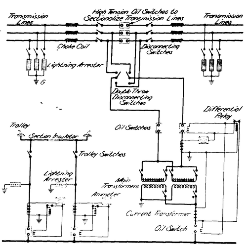
The equipment of those sub-stations already built as regards their main features and the capacity of electrical apparatus installed is identical. Each has a capacity of 400 kw, there being two 200-kw, 25-cycle transformers in-stalled. These units are wound for 33,000 volts on the primary side and 3300 volts on the secondary; they are standard G. E. transformers and are controlled on the high-tension side by two K-6 oil switches, interlocked to form a double-pole unit. The low-tension side is controlled by a single pole form K-2 oil switch, which is mounted on the back of the low-tension panel. In addition to these switches there are three K-6 oil switches, for sectionalizing the high-tension transmission line, which are interlocked in such a manner as to form a triple pole unit. Two single-pole, 33,000-volt air brake disconnecting switches are provided for connecting the oil switches controlling the high-tension side of the transformers to either side of the line sectionalizing switch, and in this manner to enable the sub-station being fed from either end of the line as desired.
Between the oil switch controlling the high-tension side of the transformer and the transformers themselves, there are four 33,000-volt disconnecting switches, two for each transformer, which enables either unit being cut out of service at will, and in a similar manner two 3300-volt disconnecting switches are provided in the secondary circuit between the low-tension oil switches and the transformers. One lead from the low-tension side of each transformer is connected to a bus situated beneath the floor that leads to the track outside of the building.
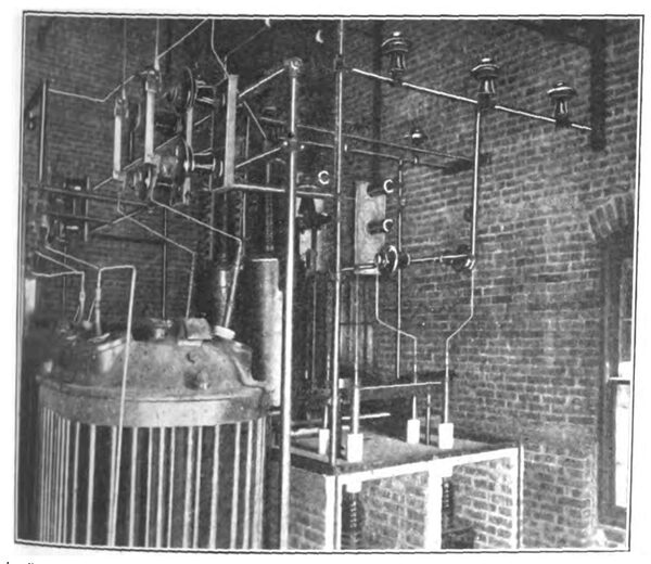
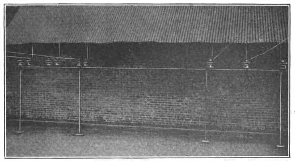
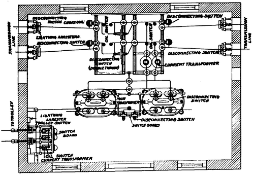
The wiring diagram given in Fig. 6 will clearly demonstrate the relative positions of the various switches and also of the other electrical apparatus, while the views reproduced in Figs. 7 and 8 will show the actual position of the high-tension wiring, etc. A plan showing the arrangement of the electrical apparatus is given in Fig. 9, which arrangement is identical in all four sub-stations. In the Danvers and Morton sub-stations three transmission wires pass through the building, while at Selbytown and Lincoln only two wires are used; their appearances will be noted in Figs. 6 and 9, respectively.
 |
| Fig. 9. — Arrangement of Apparatus in Sub-Station |
The switchboard in each sub-station consists of four panels:
(1) A line section panel on which is mounted the operating mechanism for the line section switch.
(2) A high-tension transformer panel which controls either or both of the transformers, according to how many of the disconnecting switches are in circuit; on this panel there are mounted an ammeter, the operating mechanism for the double-pole, high-tension transformer oil switch and a differential relay.
(3) A low-tension transformer panel provided with an ammeter, the operating mechanism of the low-tension oil switch and an inverse time limit overload relay of the bellows type.
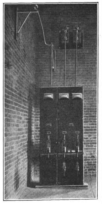
(4) A double pole feeder panel equipped with two ammeters, two oil-switch operating mechanisms, and two inverse time limit relays of the bellows type. The feeder panels are illustrated in Fig. 10, which also shows the feeders passing through the sub-station wall to the trolley.
The relays on the low-tension transformers and feeder panels are made "time limit" in order to prevent their trip-ping when a large current is taken during the acceleration of the cars; they are set for about five seconds.
| |||
| Fig. 8. — Electrical Apparatus and High-Tension Wiring in Morton Sub-Station |
The differential relays on the high-tension transformer panels are not used at either Morton or Danvers, as the baggage man in these stations is called by an alarm bell whenever an oil switch is thrown. The differential relay will be used as an overload relay without any time limit feature, but it will be set to trip only on the most severe overload conditions.
| |||
| Fig. 10. — Feeder Panels in the Morton Sub-Station |
As the sub-stations at Morton and Danvers stand back some distance from the transmission line, it was decided to bring the lines over the front of the building, and hence the lines both enter and leave the sub-station at the front. Fig. 11 will show the details of construction where the lines enter and leave the building and the method of protecting the leads from weather; this picture was taken on the roof of the Danvers sub-station.
OVERHEAD CONSTRUCTION
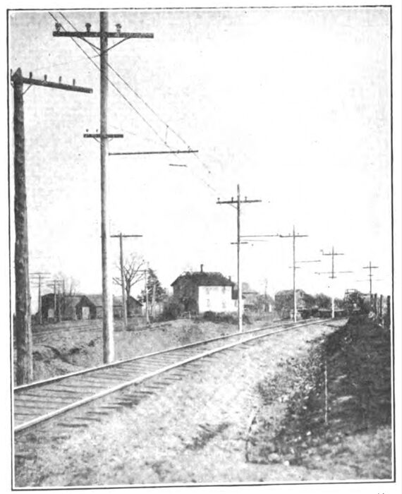
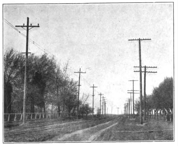
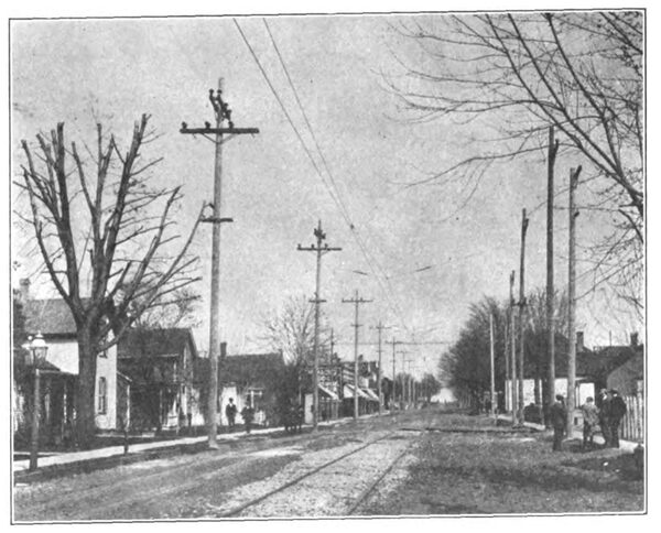
The remarks already made concerning the high-tension transmission line apply in a large measure to the trolley construction, isasmuch as the transmission line poles serve for supporting the brackets; the whole of the overhead construction has a strikingly neat appearance. As is usual with single-phase railways, the trolley is of the catenary suspended type, consisting essentially of a 000 grooved copper wire suspended from a steel messenger cable; the latter is composed of seven strands of No. 11 B. & S. galvanized steel wire. The diameter of the messenger cable is 7/16 in. The potential of the trolley is 3300 volts at 25 cycles, and the messenger is supported on Locke No. 1032 insulators.
| |||
| Fig. 13. — Transmission Line and Bracket Catenary Construction Near Bloomington |
The main portion of the road is pro-vided with the bracket type of construction, but through towns and cities of any size the span construction has been adopted. Figs. 12 and 13 are typical pictures of the line: Fig. 14 shows some special span work at the outskirts of Morton, while Fig. 15 illustrates the span construction through Danvers and further shows the point at which the high-tension transmission line enters the sub-station. This latter picture was taken before all the hangers were in position.
| |||
| Fig. 11. — View Taken on the Roof of the Danvers Sub-Station, Showing Protection of Highand Low-Tension Leads |
The details of the bracket construction will be seen by referring back to Fig. 2. The bracket proper consists of an iron pipe 2 ins. in diameter and 9 ft. 6 ins. in length spiked to the pole in the usual way. The bracket is 20 ft. above the track, making the distance from trolley to track 18 ft. and the height of the messenger cable above the track at insulators 20 ft. 6 ins.
| |||
| Fig. 12. — Transmission Line and Bracket Catenary Construction Near Morton |
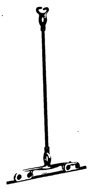
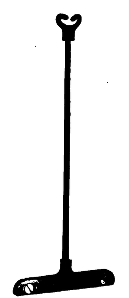
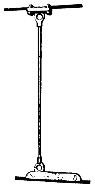
As has been previously mentioned, the poles are spaced 140 ft. apart on straight, level tangent track. The three-point suspension has been adopted, which gives a support to the trolley from the messenger every 46 ft. 8 ins. The suspension on curves and crossings are correspondingly closer together when the spacing of the poles are reduced. The illustrations, Figs. 16, 17 and 18, on the next page, will give a good idea of the form of hangers used, the views being confined to apparatus which has not previously been described in this paper. All of the line material was made by the General Electric Company. Fig. 16 shows the intermediate hangers; they consist of malleable iron "grips" or "sister hooks" and malleable iron clamps riveted to a stem of machine steel 1/8 in. and 5/8 in. The center point hanger, which is also made of malleable iron, is similar to that illustrated in an article by the author, published on page 556 of the STREET RAILWAY JOURNAL for Oct. 13, 1906. The grips of these clamps, as is the case with the intermediate hangers ,are closed when in place so as to grasp the messenger cable. Fig. 17 shows the form of hangers used with bridle pull-offs; in this instance the stem is a steel rod. The bridle arrangement consists of pulling the hanger off at both top and bottom, which keeps the trolley and messenger in the same alignment and prevents tripping. All the pull-off wires, guy wires, etc., are insulated by means of hickory strain insulators. Fig. 18 shows the type of catenary anchored hangers used. The trolley is anchored every 1000 ft., in addition to the anchors at the approach and end of each curve.
| |||
| Fig. 14. — View Showing Special Catenary Construc-Tion Through Morton |
On straight tangent track the trolley is staggered 10 ins. every 2800 ft , to prevent excessive wear of the pantograph current collector. Besides the pull-offs and push-offs at every curve, there will be steady braces at each staggering point; these steady braces are essentially the same as the push-offs; the insulating material is hickory wood.
 |
| Fig. 16. — Intermediate Suspension |
 |
| Fig. 17. — Catenary Curve Pull-Off Suspension |
 |
| Fig. 18. — Catenary Anchor Suspension |
The type of section insulator used is shown in Fig. 19; there is a section insulator at each sub-station and one between sub-stations. The dead section, where the a. c. trolley ends and the d. c. trolley begins, is composed of two such section insulators with a 40-ft. length of dead trolley between. Dead sections are situated at about a mile from the terminal at each end of the line.
THE TRACK
The track from Bloomington to Peoria is laid with 70-lb. rails of the standard A. S. C. E. section spiked to the ties in the ordinary manner. The gage of the track is standard, and is bonded throughout with G. E. 10-in. ribbon bonds with solid copper terminals 7/8 in. in diameter. The cross bonds are made of 000 trolley wire provided with standard G. E. terminals. Continuous rail joints are used throughout, which cover the bond and avoid any chance of theft. The ties are of white oak of standard dimensions, namely, 8 ft. long, with a section of 8 ins. x 6 ins. They are spaced with 2-ft. centers. There are no very severe curves on the road, but some of the grades amount to 22 per cent.
| |||
| Fig. 15. — Catenary Construction Through Danvers |
Fig. 26 illustrates the handsome steel bridge erected across the Illinois River to East Peoria. It is 800 ft. in length, with five spans, one of which is a bascule draw span operated electrically from the Peoria power house. The piers are of concrete. A truss bridge with a span of 120 ft. has been erected across the Mackinaw River at Mackinaw.
THE ELECTRICAL EQUIPMENT OF CARS
At the present time there are ten cars, and in the near future ten additional cars will be placed in service. Each car is equipped with four GE A-605 motors, which are 75-hp units capable of operating both a. c. and d. c. The motors are wound for a maximum of 250 volts; they have bar wound armatures of the iron-clad type wound with three coils per slot, which are connected to form a series drum winding. As these motors are of the same standard pattern as those which have been in operation on the Bloomington, Pontiac & Joliet Railway for the past two years and on the Toledo, Chicago & Interurban Railway since its first being in operation, it is needless to enter into a detailed de-scription here.
THE CONTROL
The control is of special interest, being of the Sprague-General Electric multiple-unit type adapted to the a. c.-d. c. operation of cars as single units or in trains of several cars. In adapting the multiple-unit system to both alternating and direct-current operation, the apparatus has been designed in such a manner as to render all changes in the connections, when the car passes from one source of power to the other, entirely automatic and independent of the motor-man; or, in other words, the system has been made automatically selective.
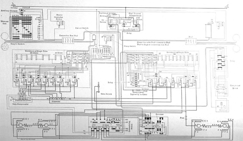 |
| Fig. 21. — Connections of Type M Multiple-Unit Control System, With Four Compensated Motors for A. C. - D. C. Operation, on the Illinois Traction System |
The master controller is of the standard type, and its function for a. c. - d. c. operation is precisely similar to when employed on straight d. c. service. The contactors are also virtually the same as those used in straight d. c. working, differing only in the fact that the former have a laminated magnetic circuit, while in the latter case the magnetic circuit is of solid metal. A standard type of reverser modified for the reception of an a. c. - d. c. operating coil is used to change the direction of rotation of the motors. The commutating switch resembles the reverser in both size and operation; its function is to commute the motor fields and to control the trolley supply to the auxiliary circuits .
| |||
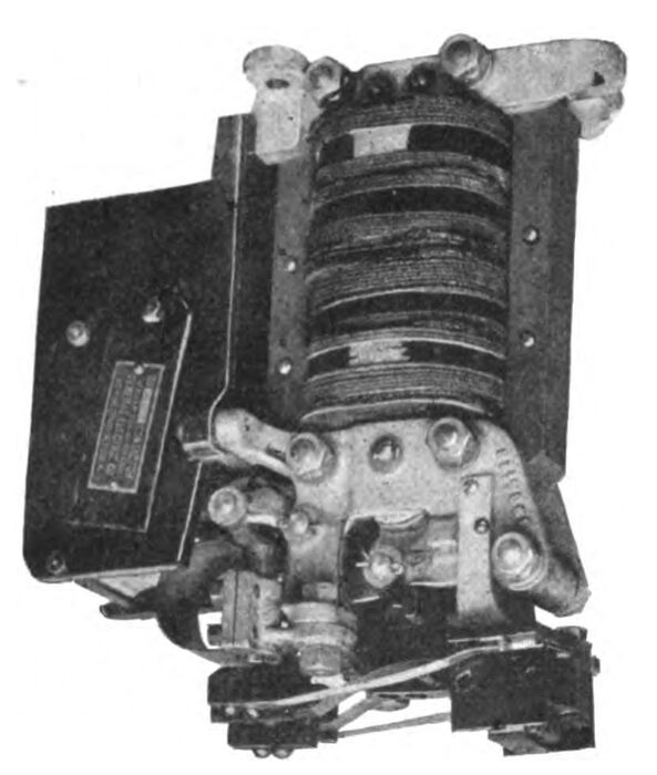
| Fig. 22. — Direct-Current Contactor — Magnet Side |
The connections which render the operation of the main a. c. and d. c. switches automatically selective are shown in the wiring diagram, Fig. 21. The operating coil of the a. c. switch is energized from the secondary of a transformer, and, therefore, is not affected by the direct current. The coil of the d. c. switch is in series with the primary of the same transformer, and, on account of the high inductance, is not affected by the alternating current.
| |||
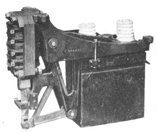
| Fig. 20. — Oil Break Contactor |
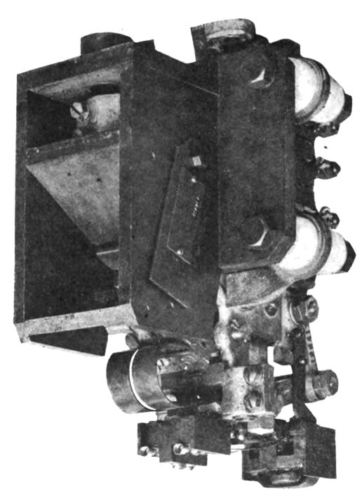
The main a. c. oil switch or contactor is shown in Fig. 20, while the two views of the direct-current switch are given in Figs. 22 and 23.
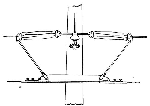 |
| Fig. 19. — Section Insulator |
The circuits for the coils of the contactors are controlled by an independent relay governed by the master controller, which relay has a gravity position for d. c. operation, and on a. c. power its coils are energized by alternating current. At the instant the leading car of a train passes from one source of power to another, all the main switches throughout the entire train and the relays controlling the circuits of the contactor coils are thrown, while the auxiliary circuits of the rear cars, such as heating, lighting, etc., remain unchanged until the dead section is passed. Each car is provided with two-wheel trolleys and a pantograph, which can be used interchangeable if desired, although the pantograph is primarily intended for a. c. operation. Potential control is employed with a. c. operation. On the first point of the master controller the motors are connected to a compensator tap giving approximately half voltage; after this point acceleration is obtained by cutting in more sections of the compensator. During a. c. running the motors are permanently connected two pairs in series, while during d. c. operation the motors are brought partly up to speed while connected four in series and then thrown into two pairs in parallel .The wiring diagrams given in Fig.21 will show all the details of connections, together with the relative position of the different pieces of apparatus one to another electrically.
| |||
| Fig. 23. — Direct-Current Contactor Circuit-Breaker Side |
All the heavier pieces of apparatus are situated under the car, and their location can be seen by referring to Figs. 24 and 25.
 |
| Fig. 24. — Plan of Car, Showing General Arrangement of Apparatus |
The protective devices, including the main a. c. and d. c. switches, together with their protecting fuses, the a. c. lightning arrester, the 1.5-kw transformer (already referred to while describing the selective system), a tube rheostat (used) in series with the coils of the main a. c. and d. c. switches). and a relay are placed in the high-tension cabinet, which is insulated with a lining of asbestos to prevent all fire risks. This cabinet is situated in the car and the general arrangement of the apparatus inside will be seen in Fig. 24. There is a small cabinet attached to the above which contains all the fuses for the auxiliary circuits.
CAR BODIES
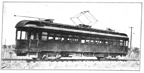
The car bodies were built by the American Car Company, of St. Louis, Mo. They are of the interurban, double-ended type provided with a vestibule at each end. Their over-all length is 56 ft., and each has a seating capacity of fifty-eight persons, the ordinary passenger compartments accommodating thirty-six and the smoker accommodating twenty two people. Each car is provided with a toilet. Fig. 26 will show the general appearance of the cars.
| |||
| Fig. 25. — Arrangement of Apparatus Under Car |
The cars are of a handsome appearance, neatly finished in the interior with weathered oak. An electric heater by the Consolidated Car Heater Company, of Albany, N. Y., is situated under each seat, and, in addition, a Peter Smith hot air heater is provided in each car The interior lighting is by incandescent lamps, while the headlights are General Electric enclosed arcs. Both trucks are motor trucks of the Brill 27-E type furnished with wheels 33 ins. in diameter. Each car is provided with a standard General Electric straight air brake equipment.
A. C. LOCOMOTIVE
The a. c. locomotive already referred to in the earlier part of this article will be used for hauling coal and miscellaneous freight over both the a. c. and d. c. sections of the system, it being equipped with a. c. motors and a. c. and d. c. control.
| |||
| Fig. 26. — Interurban Car on the Illinois Tractionsystem Equipped for A. C. - D. C. Operation |
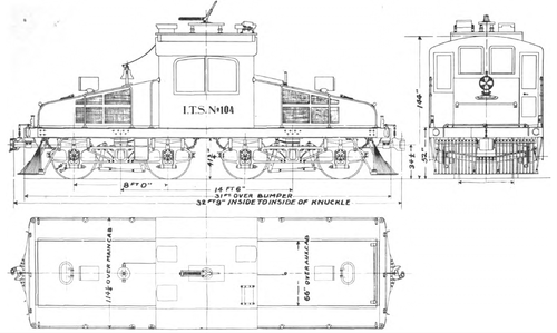
The total weight is approximately 50 tons, and it is equipped with four GEA 609 motors. These are slow speed motors designed especially for locomotive service, and on their one-hour rating have a capacity of 150 hp each. At the full load rating of the motors, 600 hp, the locomotive develops a tractive effort of approximately 15,000 lbs., which is to say it will be capable of hauling a trailing load of 500 tons on a 1 per cent grade at a speed of 15 mph. On a level tangent track it will handle the same load at 27 mph.
 |
The current collectors for both a. c . and d. c. are of the ordinary trolley wheel type, but the trolley base is specially insulated for 3300 volts. The control circuits of the loco-motive are shifted from a. c. to d. c. power automatically by a selective system similar to that already described while dealing with the car equipments. The motors are wound for 200volts, and are connected permanently two pairs in series. For d. c. control the motors are connected in the series parallel combination.
| |||
| Fig. 26. — Five-Span Bridge Crossing Illinois River at Peoria |
Fig. 28 will show the general shape of the locomotive. It has a main operating cab in the center of the platform which contains the air compressors, engineer's seat and all the operating mechanism. The sloping end cabs, which extend from the main cab to the ends of the locomotive, contain the air tank, the compensator for reducing the a. c. trolley voltage, and all the auxiliary apparatus. Narrow side platforms run from the cab to the ends, giving easy access from the cab to the couplers and switching steps, and, further, they enable the engineer at his seat to have an un-obstructed view of the track or of the switchman standing at the coupler. The trucks have cast steel side frames of the truss pat-tern.
 |
| Fig. 27. — 50-Ton Locomotive Equipped With Four Ge A-609 Motors |
The weight of the trucks and motors is carried on semi-elliptic journal box springs. The motors are nose suspended, half the weight being carried by the axles and half by the truck bolsters. The over-all dimensions of the locomotive are: Length over all, 32 ft. 9 ins., and width,9 ft.6ins.
EXTENSIONS
A list of the roads composing the Illinois Traction System, with the length and character of equipment, is appended.

