[Trade Journal]
Publication: The Electrical Review
London, England
vol. 59, no. 1504, p. 443-445, col. 1-2
POWER TRANSMISSION LINES
BY T. K. KOLKIN.
(Continued from page 417.)
·
·
·
·
Poles.Wooden poles are used as a rule, but lately also iron poles, especially in connection with long spans. In countries where wood is rather expensive, I think iron poles should receive more consideration than is given them at present. Whether they can be used to full advantage by adopting long spans is, of course, a question which has to be studied in each individual case.
As regards cost, a wooden creosoted pole with iron cross-arms for, say, six wires, including insulators and erection, costs about £3 to £4, depending upon the voltage and whether the pole has to be stayed or not; while an iron pole with cross-arms for, say, six wires, including insulators and erection in concrete foundation, would cost about £9 to £10. With wooden poles we may say the average length of span seldom extends 33 m. The first cost would thus be lower for iron poles than for wooden ones, with an average length of span of about 100 metres.
 |
Taking maintenance, depreciation and interest into consideration, we shall probably find that at an average length of span of 40-50 m. the use of iron poles will turn out cheaper than the use of wooden poles.
The size of wooden poles varies from 6 in. to 8 in. dia. at the top, depending upon the size and number of wires they have to carry. They are placed about 6 ft, in the ground. For iron construction lattice poles are used, these being cheaper and stronger than tubular poles.
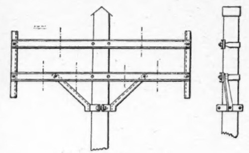
Cross-arms.Wooden cross-arms ate used in many cases, but I consider this bad practice, and should say iron cross-arms are to be preferred. In the first case, iron cross-arms are much stronger than wooden ones; and in the second case, if the wire drops from the insulator on to the wooden cross-arms it, remains there unnoticed. In many cases the cross-arm and pole start burning, causing a breakdown of the whole line; while if iron cross-aims well earthed are used in connection with star-connected generators, the breaker in the generating station will immediately open the circuit, thus preventing burning, and at the same time indicating that something is wrong. Channel iron of 3-1/2 in. x 2 in. x 2 in., or 4 in. x 2 in. x 2 in. section is a suitable size, and should be fixed to the poles by means of straps, as shown in fig. 5 and not by means of bolts.
 |
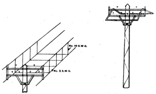
Guarding and Earthing.The cross-arms should be provided with vertical irons at each end to prevent the wires from falling down from the cross-arms in case the insulator or tie wire breaks. Where the transmission line crosses roads, railways or other wires, it is farther necessary to put a guard netting underneath and at the sides of the transmission wires, as shown in fig. 7. This netting should be efficiently connected to earthwhere foreign wires cross the transmission line a similar protection should be provided above the line. Another safety device sometimes used is shown in fig. 8. The idea is that in case one of the wires breaks, it will strike the metal guard before it falls to the ground. This may be satisfactory in most cases, but it is a question whether it is absolutely safe when the guard is covered with snow and ice. In this connection it should be pointed out that it is advisable to earth the pole itself in addition to the cross-arms. The earth wire used for the cross-arms can also be used for earthing the pole by slinging it two or three times round the pole. A galvanised iron wire No. 8 S.W.G. is generally used and is fixed to the pole by staples.
Tests have been carried out on a 7,000-volt transmission line with unearthed poles. The wire of one phase was placed on the cross-arm, while the wire of the second phase was placed on the cross-arm of a neighbouring pole: a voltage difference of about 350 volts was found between pole and "earth," and a voltage difference of about 300 volts per metre ran of the pole. On earthing one of the poles a voltage difference of about 650 volts was measured between "earth" and the unearthed pole, and a voltage difference of about 550 volts per metre run of the pole for the first 3 metres from the ground.
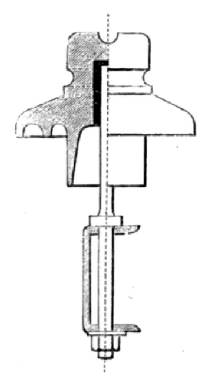
Insulators and Bolts.--Porcelain insulators are, as a rule, used in Europe.
In selecting an insulator it should be borne in mind that it is of just as great importance (1) that the insulator be provided with a strong shoulder and neck; (2) that it be designed to transfer the strain of the wire to the bolt without leverage on the insulator; and (3) that it be grooved to fit the wire to be used as that it should have a good insulation surface. The insulators are either screwed on to the bolt. or fixed by means of sulphur, cement, or oiled hemp. The last method seems to protect the insulator in the best way from cracking, and at the same time gives sufficient mechanical strength. As regards bolts, 5/8 in. galvanised iron bolts are used for small wires, but for wires above 1 sq. in. section, bolts of 3/4 in. diameter should be used unless the conditions are exceptionally favourable.
Erection.In erecting the poles sharp angles are to be avoided, and where a change in the direction of the transmission line is necessary the latter should be carried in a long "sweep." Care should be taken that the insulators on three consecutive poles are, as nearly as possible, mounted in the same plane, so as to avoid sharp vertical angles. The ordinary insulator is not designed to take vertical strains, and the contraction of the wire due to fall in the temperature will either bleak the tie-wire or lift the insulator from the bolt. In order to avoid such sharp angles, it is necessary in some cases to put np one or more long poles, or to increase the length of the span, with steel poles for the long span.
 |
Copper Wires.The copper wires should be semi-bard or hard-drawn. Larger conductors than 2 sq. in. section should he avoided. as they are very troublesome to erect. If a much larger section than 2 sq. in. is required per phase or pole, the conductor should be split up into two or more wires as the case may be.
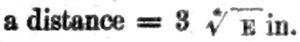
Spacing of insulators.A general rule regarding the distance between the insulators cannot be given. For pressures up to 40-50,000 volts, a distance = 3 in, will in most cases be found sufficient, unless long spans are used. In the above formula E represents the voltage. The minimum distance should not be lees than 12 in. to 15 in.
For pressures exceeding 15-20,000 volts, it will be found that the placing of more than one three-phase circuit on each pole line will lead to rather poor arrangements, unless steel poles and cross-arms are used. For pressures above 50,000 volts it will be found pressures necessary to place the insulators at a greater distance than the above formula would indicate.
Static Discharge.--This is not very large for pressures up to, say, 50,000 volts, but when the pressure is increased to 60,000 volts or above, it becomes a serious matter. The static discharge depends, naturally, to a great extent on the climatic conditions.
 |
Extensive tests have not, as far as I know, been carried out. (in the Telluride transmission line, Colorado, some tests have been carried out, the results of which were as follows:
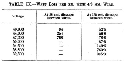 |
A loss of 885 watts per km. would mean a total loss of about 175 KW. on a 200-km. transmission line. This, in addition to surface leakage and ohmic losses, is too much in most cases. By increasing the distance between the wires to 200-300 cm., we may expect a loss of 150 or 200 watts per km. The above, however, shows that at a voltage of 60,000 and above, the static discharge has to receive careful consideration.
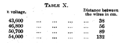 |
Table X gives the distance between the wires at various voltages at which the effect of the static discharges begins in accordance with Prof. Ryan's theory, whereby the diameter of the wires is also taken to be 4.3 mm.
 |
In the above E is the effective voltage, and the max. voltage is taken to be = 1.71 E.
In this connection I would point out that the effect of the discharge depends to a great extent on the diameters of the wires This begins at a much lower voltage for small wires than for large ones.
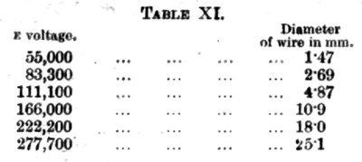 |
Table XI gives some idea regarding this; the table is also drawn up in accordance with the said theory, for an average distance between the wire of 122 cm. at 21° C., and a barometric pressure of 760 mm.
Lightning Protection.The so-called lightning arresters are supposed to protect against lightning discharges as well as atmospheric discharges. The types mostly in use are:
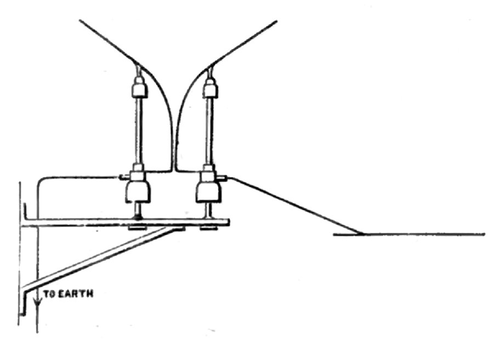
1. The horn type arrester, which consists of two copper wires bent as shown in fig. 9, one wire being connected to the overhead conductor and the other connected to earth. The distance between the horns should be about 1 mm. for 1,000 volts, with a minimum distance of 2 mm. if the arrester is installed inside a building, and a minimum distance of about 5 mm. if it is mounted in the open.
2. The Warts type lightning arrester, which consists of a series of air gape with shunt and series resistance to earth.
Lightning arresters are provided where overhead wires leave or enter a buildingone for each wire. If the transmission line is long and exposed, lightning arresters are also placed along the line at suitable places. Each lightning arrester should be provided with an efficient earth plate either of cast-iron or tinned copper of at least 10-15 sq. ft. area.
On high-tension transmission lines, for, say, 30,000 volts and above, the lightning protection is an important matter, and it has been found good practice to install several arresters of different types in parallel.
Over-voltage.On long transmission lines, especially in combination with cables, in many cases over-voltage is liable to break down the insulation and cause trouble. Fuses preventing a breakdown due to excessive current have, so to say, always been used, while voltage-limiting devices, with the exception of field-discharge resistances, have only lately received consideration. I presume many a breakdown ascribed to "bad insulation" is in reality due to over-voltage.
It is claimed by many that the lightning arrester takes care of over-voltage. This may be, to a certain extent true, in so far as it takes care of a high over-voltage.
A sensitive voltage limiting device must have a small air-gap, and as the discharge is small, it can have, or should have, a large resistance to earth.
These two conditions would make it unsuitable as a lightning arrester, which has to take care of bevy discharges. Some of the cable manufacturers insert a weak insulation in their joint boxes. Such boxes are provided with pilot wires, which indicate breakdown at a particular point. This arrangement may cause inconvenience, but still it is to be preferred to an "unexpected" breakdown, which may cause considerable damage and require time to locate. Lately a device has been used in Europe, and also in America, which, I understand, has given very satisfactory results. This simply consists in connecting the wires to earth by means of a resistance; the latter is so large that the current at normal voltage does not exceed .1 to .2 ampere per phase.
On a 50,000-volt transmission line this would, of course, mean a loss of 5 to 10 KW. per phase. Still, this is not a serious matter where several thousand kilowatts are transmitted, and where only a few points need such a protection.
The voltage rise, or "over-voltage" referred to, is caused by resonance of harmonic waves of higher degree. The lower the periodicity of these waves, the more "dangerous" they are. A high capacity causes a low periodicity, and this is why large armoured cables possessing a high capacity are liable to breakdown, especially where energy is being supplied to motors only. Where incandescent lamps are being fed the danger is not so great.
The reason is evidently that the resistance of the lamps resisting the waves is very high, whereas that of the motors is comparatively low, and the B.M.F. of the motors does not counteract the waves of higher degree.
