[Trade Journal]
Publication: Electrical World
New York, NY, United States
vol. 48, no. 19, p. 911-914, col. 1-2
The Electrical Equipment of the Camden-Atlantic City Railway.
THE Pennsylvania Railroad Company owns two roads connecting Atlantic City with Camden, N. J., both of which were originally operated by means of steam locomotives. During the present year, however, the longer of these routes, which handles a large local traffic, has been electrified because it was estimated that electric traction would prove more economical than steam haulage. The power house, sub-station equipment and the transmission line are laid out with a view of supplying power for the operation of an express service from Camden to Atlantic City, consisting of three-car trains running on a headway of fifteen minutes in each direction at a speed on straight level track of 60 miles per hour, and a local service of two-car trains at half-hour intervals and single cars at ten-minute intervals:
The electrified system extends from Camden via Newfield, to Atlantic City, a distance of 65 miles, and from Newfield to Millville, a distance of 10 miles. In addition to the erection of a power house, the work has called for the building of eight substations, one of which is in the power house, the electrical equipping- of approximately 150 miles of single track, the building of 71 miles of duplicate high-tension transmission line, and the building of 68 motor cars.
| |||
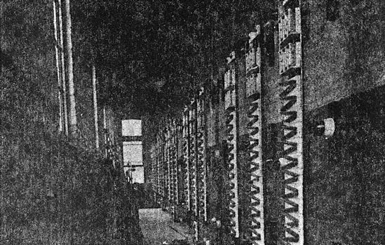
| Fig. 1. View of Interior of Westville Power Station. |
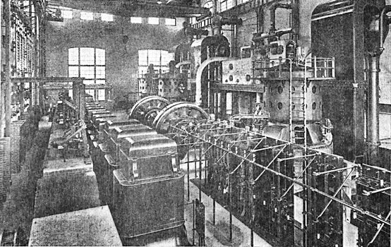
The power house is situated at Big Timber Creek, just to the north of Westville, N. J., at a point 5.6 miles from the Camden terminal, where there is an abundance of water for boiler feed and condensing purposes. The present normal capacity of the generating station is 6,000 kw, which is obtained from three 2,000-kw, 6,600-volt, 25-cycle, three-phase Curtis turbo-generators. Space is provided, however, for an additional 2,000-kw turbogenerator set with the necessary auxiliaries. The station contains at present two 75-kw, 125-volt Curtis turbo-exciter units, nine 700-kw, 6,600 to 33,000-volt air-blast transformers and three blowers, each having a capacity of 20,000 cu. ft. of air per minute. The area of the power house is 17,069 sq. ft, and the cubic contents amounts to 829,113 cu. ft., thus giving 2.13 sq. ft. and 103.6 cu. ft. per kw, based on 8,000 kw as the ultimate capacity of the present structure.
The boiler house is furnished with 12 Stirling water-tube boilers arranged in pairs forming six batteries. Each boiler is rated at 358 hp and is furnished with a superheater capable of delivering steam at 175 lb. pressure and at a temperature of 125° F. in excess of that of saturated steam. The coal is dumped from the railway cars into a receiving hopper over which rails are laid. The receiving hopper has a slanting bottom to feed the coal by gravity through a valve, which is opened only when the skip is in the correct position for loading. The loaded skip is raised by means of a hoisting engine till it reaches the level of the deflector, when it is automatically tipped into the crushing hopper, the smaller coal passing through the screen and the larger coal being broken in the crusher in transit. From this hopper the coal is fed into the gravity return car by means of valves at the bottom, when it is conveyed by an automatic railway over the coal bunkers into which it is tipped. From these bunkers it is again fed to the coal cars on the tracks on the boiler room floor. The ashes are taken from the boiler house in cars and dumped into the receiving hopper, from which they are raised in a similar manner to the coal. The ashes are conveyed from the ash chute to the ash storage bin, from which they are conveyed by means of a chute to cars on the railway track.
The 33,000-volt, three-phase current is reduced in pressure and converted to direct current at 650 volts in eight sub-stations distributed along the line as follows:
One is located in the power house at Westville. There are three terminal sub-stations situated respectively at South Camden, Clayville and Atlantic City, and four intermediate sub-stations, one at Glassboro, one at Newfield, one at Mizpah, and one at Reega.
 |
The equipments in the several different sub-stations vary according to the requirements of the portion of the road they supply. The above table shows the number and capacity of rotary-converters installed in each sub-station, together with the extra, capacity provided for.
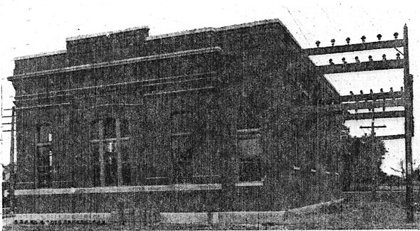
The sub-station buildings are of red brick, trimmed with Indiana limestone facings, and the floors are of concrete. Each sub-station is furnished with a hand-operated crane, capable of handling any of the machinery installed.
The rotary converters are all of standard General Electric design, and are capable of running at 50 per cent overload for two hours with a temperature rise not exceeding 35°. The transformers are all supplied with taps giving one-third and two-thirds of the working voltage to enable the converters to be started from the alternating side. This method of starting does not require synchronizing, and should the direct polarity of the machine chance to come in the wrong direction it is readily changed by means of the field reversing switch, which is provided for this purpose. By this method any of the rotary converters can be started, run up to full speed, and be delivering power to the line within a minute.
Three air-cooled transformers are provided for operation in conjunction with each rotary, and these are located in each case with a view to the further extension of the sub-station; as they are all of standard design it is not necessary to go into details regarding their construction.
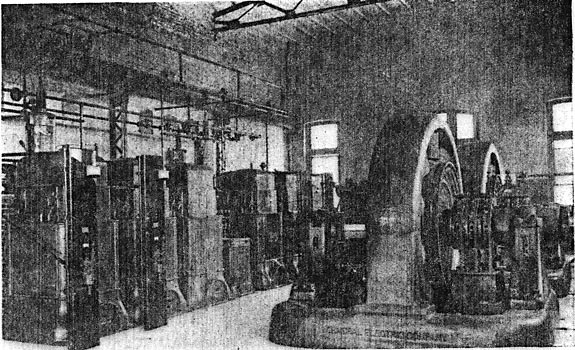
| |||
| Fig. 2. Transformers, Lightning Arresters, Etc., Westville Power House. |
The disconnecting switches and lightning arresters in each sub-station are located in a separate room (Fig. 8); the high-tension circuits are of bare copper wires supported on insulators on a pipe framework, and each pole of the oil switches is enclosed in a separate brick compartment. In all cases the instruments and oil switches are of General Electric design.
 |
| Fig. 3. Transverse Section of Power House. |
 |
| Fig. 4. Plan of Power House. |
 |
| Fig. 5. Plan of Typical Sub-Station. |
 |
| Fig. 6. Transverse Section of Typical Sub-Station. |
For the purpose of illustration, the intermediate sub-stations with two 750-kw rotary converters are selected as being typical. Figs. 5 and 6 are respectively the plan and the transverse section of a typical substation.
The 33,000-volt transmission line is in duplicate throughout. It consists of six No. 1 B. & S. hard-drawn solid copper wires mounted on porcelain insulators. The poles are of chestnut, their height being 45 ft., with extra long poles where special conditions require. They are spaced 125 ft. apart, but at street crossings the spacings are reduced to 100 ft. Head guys are used at distances of approximately one-quarter of a mile. There are two cross arms, the top arm being 12 ft. in length, carrying four insulators. The six wires form two inverted equilateral triangles, the insulators on each triangle being 42 in. apart. The wires in each triangle are transposed through one complete spiral between each sub-station.
The cross arms are fastened to the poles by means of bolts and as an additional support they are stiffened with galvanized-iron braces. Locke insulators are used, made in three pads and designed to withstand double the working pressure. Each petticoat was tested separately, the top section to 45,000 volts. In each case these tests lasted four minutes, and following this the assembled insulator was subjected to 85,000 volts for ten minutes, and also a precipitation test was made at 52,500 volts. The in are mounted on iron pins.
A unique feature of the transmission line is the means for protection from lightning, which consists of a seven-strand galvanized steel cable 5/16 in. in diameter strung for the entire length of the line on top of the transmission poles, 4 ft. above the nearest active wire, and provided with ground connections at every fifth pole. This form of protection from lightning is believed to be an efficient supplementary adjunct to the arresters.
| |||
| Fig. 7. View of Exterior of Glassboro Sub-Station. |
The rails used for the working conductor are of the Pennsylvania Railroad standard cross-section and composition, weighing 100 lb. per yard, and have an electrical conductivity about equal to that of a copper rod of 1,200,000 cir. mil. This type of third rail was used in order that it might be interchangeable with the track rails.
The rail insulators are of reconstructed granite, and are held in position by a metal centering cup which is secured to the long ties by means of a lag screw. The insulators are 10 in. long and 5 1/2 in. broad at the base, with an effective depth from the bottom of the rail to the tie of 3 1/2 in. An advantage of this method of securing the position of the insulator is that on the ties being depressed by the passage of a train no tension strain is brought to bear on the insulators. The insulators are spaced about 8 ft. apart. The top of the third rail is 3 1/2 in. above the top of the track rails, and its gauge 26 in. distant from the gauge line of the adjacent track rail, these dimensions constituting the standard of the Pennsylvania Railroad, and the Long Island Railroad, and also interchangeable with the Interborough Rapid Transit of New York City.
| |||
| Fig. 8. Lightning Arrester Room, Newfield Sub-Station. |
Between Newfield and Millville and on the stretch of track between Haddon Avenue and South Gloucester is of the span type, an overhead trolley construction is used -with -poles spaced at a distance of 100 ft., and where practicable the high-tension transmission poles have been used for supporting the span wires. Through Camden the greater part of the trolley construction is on tubular steel poles. The trolley is suspended 22 ft. above the top of the track rails.
There are no copper feeders used on the third rail, but those for the trolley lines are as follows: Two 750,000-cir-mil feeders from South Camden to Haddon Avenue; one 750,000-cir-mil feeder running from South Camden to Brown's Crossing. Both of these form a conjunction with the third rail. The copper feeder between Newfield and Millville is of 500,000 cir. mil section.
| |||
| Fig. 9. - View of Interior of Sub-Station at Atlantic City. |
The trolley wire is of No. 0000 grooved section. The span wires are of stranded galvanized steel 3/8 in. in diameter. The lightning arresters are installed at approximately 1,000 ft. apart. All pull-offs, strain ears, feeder ears and splicing sleeves are of bronze, and as those items, together with all other line material, such as frogs, etc., are of standard pattern, a further description would be superfluous.
For initial service sixty-two passenger cars and six combination baggage and mail cars have been provided. All of the cars are motor cars, the motor and control equipment being the same on all.
In preparing the design of these cars, the engineers of the railroad followed the general design of the standard Pennsylvania Railroad coaches, except that the height is less than the standard to decrease the weight, the shape of the roof is changed and the interior finish is of mahogany instead of oak. The seating capacity is 58 passengers.
Each car is provided with a 50-cp incandescent electric headlight and two electric markers or route lamps on the hood at each end. Each car has two trolleys, each with a retriever, and on the roof between the trolley bases there is a box containing the lightning arrester, trolley cut-out switch and trolley fuse. The cars are heated by Gold cylindrical heaters, one being under each seat, a total of 28 heaters per car. There are two coils in each heater, thus providing three degrees of heat.
The power equipment of each car, consists of two General Electric 69 motors which are 200-hp units, while the control system is of the automatic multiple-unit type. The controllers are so arranged that current is cut off from the motors throughout the train and the brakes are applied automatically should the motorman release his hold of the controller handle.
For the sake of brevity, these equipments will not be entered into in detail, as they are of standard General Electric design. With the exception that each car is provided with a trolley and third rail shoe, the control system is similar to that on the 24 equipments supplied to the Boston Elevated road about eighteen months ago.
The conversion of the lines of the West Jersey & Seashore Railroad above described from steam to electric traction was carried out by the following organizations: The construction of the terminals, inspection sheds, double tracking, changes in existing tracks, grading, new bridges, changes in telegraph lines, and installation of a special telephone system were carried out by the regular engineer and maintenance of way departments of the Pennsylvania Railroad Company.
The installation of the interlocking plants and automatic block signaling was carried out by the Union Switch & Signal Company in accordance with plans of the signal department of the Pennsylvania Railroad Company.
The new cars and trucks required for the electric service were designed by the motive power department of the Pennsylvania Railroad Company.
The entire contract for the electrical equipment, including the construction of the power house, sub-stations and the electrical equipment on the cars, was awarded to the General Electric Company, and in accordance with the plans and under the supervision of Mr. George Gibbs, chief engineer of electric traction, in consultation with the officers of the railroad company. Stern & Silverman, of Philadelphia, were appointed by the General Electric Company as their general sub-contractors, and the Scofield Company, also of Philadelphia, acted as general engineers for the power house and sub-contractors for the piling and foundations. The whole of the electrical work was under the personal supervision of Mr. W. B. Potter, engineer, railway engineering department, General Electric Company, directly assisted by Mr. J. Elliot Hewes, Mr. C. E. Eveleth and Mr. W. H. Clapp.
