[Trade Journal]
Publication: The Electrical Engineer - London
London, England
p. 112-113, col. 2, 1
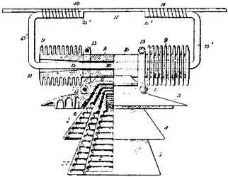
High - Tension Insulators.-- In the insulation of potentials of 60,000 volts and over serious difficulties arise by reason of leakage of current over the surface of the insulator, due principally to dust and moisture upon the surface of the insulator. It is, therefore, necessary to provide an insulator which will resist high voltages and operate in rainy weather, and not be liable to deterioration from accumulations of dust upon its surface. Au insulator which has been designed to meet these requirements has been patented by Mr. F. G. Baum. According to the Western Electrician, the surfaces which arc exposed to the weather to a sufficient extent to be effectually washed off by the rains, are in a position to have their insulation impaired during a storm by the coating of moisture. Therefore, the inventor, in carrying out his ideas, makes use of a combination of weather-washed surfaces with petticoat-protected surfaces. Referring to the drawing in which like parts are designated by the same reference sign, 1 indicates a petticoated insulator of substantially the ordinary form, having petticoats, 2, 3, 4, and 5, on it, each of which has its interior face ribbed or corrugated, so as to provide greater insulating surface. The cement fillings by which the different petticoats are secured together are shown by 6. The upper petticoat, 5, is provided with the usual annular groove. 7, for the reception of any clamping or securing devices. Groove 7 is used for supporting a supplemental and weather-washed insulating member, which constitutes an essential feature of the invention. A practical form of this supplemental insulator is shown in the illustration and comprises an insulating tube, 8, of porcelain or other material, having annular ribs, 9, extending along a considerable distance at each end. The central portion of the tube is conveniently left smooth, as at 10, and fits in the groove, 11, on the petticoat, 5. Supporting straps are shown at 12, by which the tube, 8, is secured to the body of the insulator, 1. In the drawing these straps comprise stamped metal plates, which are slightly bent to surround the tube, 8, and the groove, 7, and are clamped into place thereon by clamping bolts, 13. The particular method of supporting the tube, 8, from the insulator, 1, is not important, it being merely essential to secure the two together, so as to leave the ribbed ends, 9, exposed and out of contact with the main insulator. The supplemental insulator, 8, is provided with means for holding the line wire in place, and the supplemental insulator is shown as having a longitudinal square hole, 14, with slightly-flared ends. Within this hole is inserted a supporting frame of metal rod, 15, which may he held in place by a layer of cement, 16, at its central portion. The ends, 15, of t he supporting frame are afterward bent upwardly and toward one another, so as to form aligned sections, 152, to which the line wire may be conveniently attached. 17 indicates the line wire, which is strapped to the frame, 15, by binding wire, 18. On account of this arrangement the insulation strain lies between the cement, 16, and through the body of the insulators, 8, 5, 4, 3, and 2, which is almost an absolute insulation for practical purposes. Surface leakage may only take place along the interior walls of the supplemental insulator, 8, over the entire area formed by the exterior ribs, 9, and finally over all of the successive exterior and interior surfaces of the quadruple petticoated main insulator, 1. In this action it may be observed that the leakage must always traverse an extensive weather-washed surface-namely, the ribs, 9-and an extensive protected surface-namely, the interior ribbed faces of the quadruple petticoats, 2, 3, 4, and 5. The ribs, 9, being washed by the rain, are always clean, and should secure perfect insulation in dry weather. In wet weather the interior surfaces of the petticoats, 2, 3, 4, and 5, are in condition to effectively insulate the current.
 |
