[Trade Journal]
Publication: Electrical World
New York, NY, United States
vol. 29, no. 23, p. 721-723, col. 1-2
The Niagara Fails Power Company.
PERHAPS no plant has ever been so much and so fully described as that of the Niagara Falls Power Company. The colossal hydraulic developments which were undertaken to supply power for the generation of electric current on a scale hitherto unknown, the enormous machinery which was installed, the serious attempt to transmit a very great power to a considerable distance, and the discussion by electricians the world over of the problems involved in its construction, have all contributed to make it the most interesting development of the electric arts. It has been so frequently described in all its parts that anything more than a brief summary would seem to be out of place at this time.
| |||
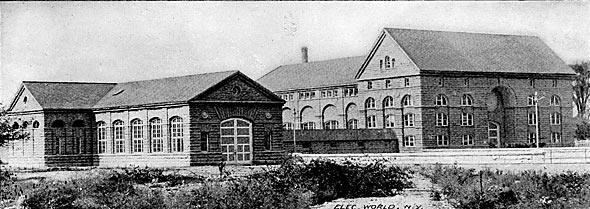
| Exterior of the Niagara Falls Power Company's Power House. |
| |||
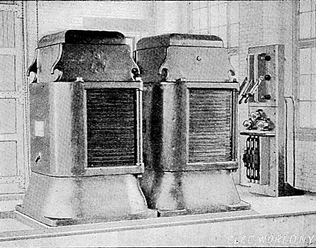
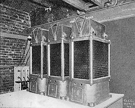
| Static Transformers at Niagara End of Buffalo Transmissio Line. 200 Volts 2 Phase to 11,000 Volts 3 Phase. |
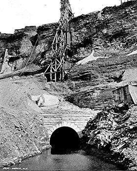
The original idea which has been carried into such elaborate execution was first suggested by Thomas Evershed over fifty years ago. His plan was to construct a canal leading from the still water of the Niagara River at a point sufficiently far above the falls to permit the establishment there of docks for shipping, and to drive a tunnel from the lower end of the river, below the fall, to a point under this canal, thus securing a very high head of water without in any way detracting from the beauty of the scenery. This plan has been carried out, perhaps more fully than Evershed contemplated, and now 15,000 horse-power of the contemplated 50,000 is actually being developed, while the machinery for 25,000 horse-power additional is being rapidly installed. The canal which brings water from the upper level of the river to the power house is about 180 feet long and twelve feet deep, having a cross section sufficient to deliver water for the generation of 100,000 horse-power. It will not, however, be a difficult matter to enlarge this canal, should that prove desirable, to two or three times its present capacity.
| |||
| The Portal of the Great Hydraulic Tunnel. |
The wheel pit in which the great turbines run is an excavation 180 feet deep, 30 feet wide and about 200 feet long, every inch of which is excavated in the solid limestone rock. Into this pit, the penstocks, ten in number, which are constructed of steel and are nearly eight feet in diameter, bring the water down to the turbines under a head of 180 feet. These turbines present several peculiar and novel features. They were designed by a firm of Swiss engineers, who had had considerable experience in similar installations in their own country, and constructed by the I. P. Morris Company, Philadelphia. Each turbine is capable of delivering 5500 horse-power when operating at its normal speed of 250 revolutions per minute. The enormous weight of the turbines and their vertical shafts necessitated the balancing of the wheels, which was accomplished by admitting the water at the lower side of the cases, thus providing an effectual counterbalance.
| |||
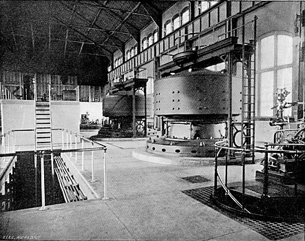
| Two of the 5000- HP Dynamos, Niagara Falls Power Company's Station. |
| |||
| Static Transformers at Buffalo End of Transmission Line.. |
The main shaft consists of a steel tube thirty-eight inches in diameter with walls three-fourths inch thick. At the bearing the shaft becomes solid and is reduced to eleven inches in diameter.
The great dynamos are mounted directly on the upper ends of the vertical shafts and are revolved in a horizontal plane. The armature is cylindrical and stationary and has a two-phase winding, giving at the normal speed 2200 volts and 850 amperes in each phase. The field magnet is a steel ring revolving outside of the armature and carrying twelve pole-pieces, which project inwardly. The exciting current is fed through two rings at the top of the machine. The governing of each turbine is accomplished by means of a centrifugal governor designed by Messrs. Faesch & Piccard, the designers of the turbines. These governors are not different from others of the mechanical class, and while operating very successfully merit no detailed description.
| |||
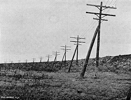
| A Curve on the 11,000-Volt Niagara-Buffalo Transmission Line.. |
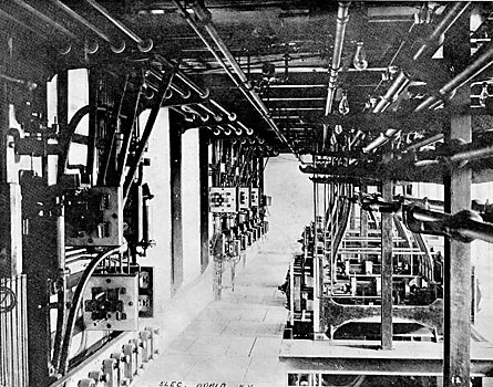
The controlling arrangements for the handling of the enormous current given out by these great generators are operated entirely by compressed air. There are two sets of bus bars so arranged that any combination of machines and circuits can be made to either. There is a resistance provided to short circuit the discharge current of the fields when they are cut out. On the switchboard a panel is provided for each dynamo, containing an ammeter, wattmeter and voltmeter for each phase, a direct current ammeter in the exciter circuit and a synchronoscope. The arrangement of the dynamos and the switchboard in the building can he best seen from the illustrations herewith.
| |||
| Two-Phase Switchboard by Compressed Air, Niagara Falls Power Company's Station. |
The currents generated by the large dynamos are at 2200 volts, two-phase. For the railways in Niagara Falls these are transformed by a static transformer in each phase to about 400 volts and led to a rotary converter. For the Buffalo transmission they are stepped up to 11,000 volts, three-phase, by two gigantic static transformers. These are so arranged that a change of connections will give 22,000 volts, should it be decided to use this pressure on the line. The insulators and cables can easily stand it.
| |||
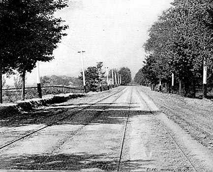
| View on the Niagara Falls and Buffalo Railway. |
The power station is a work of pleasing simplicity of architecture, though with some pretensions to decorative design. It is constructed of the limestone quarried from the wheel-pit and stands at the back of a well-kept lawn. The end of the building toward the extension of the wheel-pit is temporarily closed with a board partition, so that the building may be indefinitely extended as the requirements demand additional wheel-pit excavations and extension of the generating plant. Near the building, but on the opposite side of the canal, is a small building of the same general style, containing the transformers, the two being connected by a conduit or hallway for the mains. A visitors' gallery is provided in the main dynamo house, and this has proved a very attractive point for many tourists at Niagara Falls. In the offices on the ground flour of the dynamo house are a very elaborate set of registering and recording instruments, which are kept constantly in circuit, and show at a glance the condition of the lines and dynamos. The visitor to the plant is struck at once with the extreme neatness of his surroundings and by the cyclonic wind which is stirred up by the revolution of the enormous dynamo fields. From the transformer house radiate the various lines to Buffalo and elsewhere, which carry away the power generated in the main plant. The transformers, two in number, for the Buffalo transmission line receive the two-phase current at 2200 volts and send it out as three-phase current at 11,000 volts. The switchboard and lightning arresters for this line are beautiful examples of careful workmanship.
| |||
| Three 5000- HP, 2200 Volt, Two-Phase Dynamos in Niagara Falls Power Company's Station. |

