[Trade Journal]
Publication: Electrical World
New York, NY, United States
vol. 49, no. 21, p. 1025-1029, col. 1-2
Hydro-Electric Developments on the Catawba River, South Carolina.
IN our issue for July 23, 1904, there was given a description of the hydro-electric plant of the Catawba Power Company, at Indian Hook Shoals, on the Catawba River, in South Carolina. This company has been merged with the Catawba Electric & Manufacturing Company, under the name of the Southern Power Company, which now owns or controls nine water-power sites in the so-called Piedmont Section in the Carolinas. The total power available is 100,000 kilowatts.
Work is now being hurried to completion on the development at Great Falls on the Catawba River, which consist of a series of falls and shoals having a total head of 176 feet in a distance of about 8 miles. In this development there will be three separate plants, the down-stream one giving 60 ft fall, the up-stream one 40 ft. and the middle one 72 ft The latter plant, known as the Great Falls Station, is described in detail below.
HYDRAULIC DEVELOPMENT.
The hydraulic part of the development consists essentially of a low spillway dam at the head of Mountain Island to deflect the water into the western channel. Flowing through this channel nearly to the foot of the island, it is then forced through the headgates of the canal by another spillway dam. An extension of this dam serves as an overflow weir between the canal and the river. From this point the stream is carried by a canal through a natural valley about miles to the power-house and a retaining bulkhead built across the valley, while below the power-house the tailrace carries off the spent waters, 1/4 mile to Rocky Creek, in which channel it is again carried to the river bed.
| |||
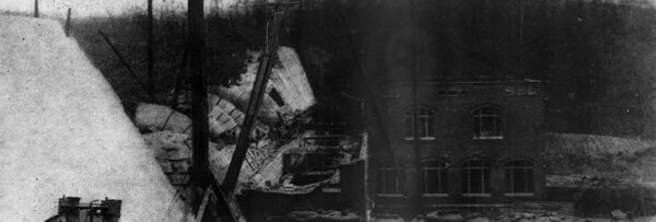
| Fig. 1.View of Power House Under Construction. |
| |||
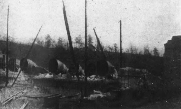
| Fig. 2. -- Turbine Feeder Pipes. |
At the lower end of the canal the water is impounded by a concrete retaining wall, in which are built the intake flumes for the turbines, and below which is located the power house which virtually forms a part of the retaining wall. An additional side of the power house is formed by the arches spanning the tail-races from the turbines; the building is 250 ft. long, and 37 ft. wide.
TURBINES.
There are 10 turbine units each consisting of a pair of horizontal twin turbines with top inlet and center discharge; of these, eight are 3900-kw machines designed for 225 r. p. m., while two are 52S-kw machines designed for 450 r. p. m. Two of the larger turbines were built by the Holyoke Machine Company, while all of the other turbines were furnished by the Allis-Chalmers Company. The intake of water to each turbine is regulated by means of a Lombard governor.
GENERATORS.
The generating equipment consists of eight 3000-kw 60-cycle, 2300-volt alternators and two 400-kw, 250-volt direct-current exciter dynamos. Each alternator is so designed that when the field circuit is supplied with 200 amperes at approximately 160 volts, it will deliver its normal output at 100 per cent power-factor, while the exciting current must be 260 amperes when the alternator delivers the normal power output at a power factor of 80 per cent. At 100 per cent power-factor the voltage variation from full load to no load does not exceed 7 per cent.
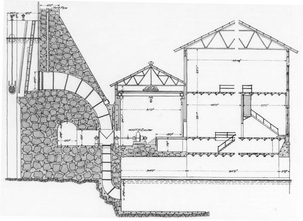 |
| Fig. 3 -- Cross-Section of Dam, Power House and Transformer House. |
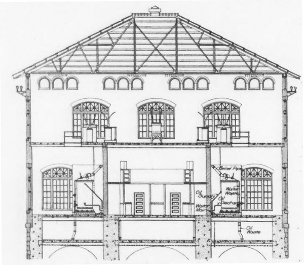 |
| Fig. 4 -- Sectional View of Transformer House. |
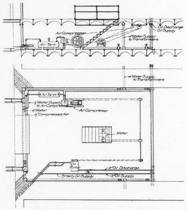 |
| Fig. 5 and 6 -- Elevation Plan of Oil, Water and Air Systems. |
TRANSFORMERS.
Adjacent to the power house with which it possesses one wall in common is located the transformer house, which is practically a three-storied building, 75 ft. in width and 85 ft. long. This building contains four banks each consisting of three transformers. Each transformer is rated at 2000-kw, 2000 to 44,000 volts, and is insulated with oil and cooled by water. The full load efficiency of each transformer is 98.4 per cent, the regulation at full load is 95 per cent for 100 per cent power factor, and 2.9 per cent for 85 per cent power-factor. Cooling water is supplied by gravity through pipes tapped into the heads of the exciter turbine cases.
The transformer tanks are designed to withstand a pressure of 150 lbs. per sq. in. and in order to provide against damage in case of explosion each tank is connected through a relief valve to a 6-in. vent pipe discharging outside of the building. Transformers are mounted on flanged wheels and stand in their respective compartments on 30-lb. rails supported on concrete pedestals. A transfer carriage operates upon a track in front of each row of transformers, and any of these may readily be removed from its support onto the carriage and thence into the power-house, where it is accessible to the crane. All transformers are connected to a pipe system by which carbonic acid gas may be admitted to the tanks in case of fire. The carbonic acid gas generator and pressure tank are located in the basement of the transformer house, and from them a main pipe extends to a cabinet in the low-tension switching room, where the distributing pipe to the several transformers branch off. Each branch pipe is provided with a valve numbered to correspond to that of the transformer to which the pipe is connected, so that by opening the proper valve a fire may be extinguished in any tank. A pipe lead also extends to the second story, whereby means of a hose connecting from a floor box any of the apparatus there may be reached.
Oil for the transformers may be supplied either by gravity or under pressure from a storage tank outside of the building, or by reversal of a pump it may be drawn off and returned through a filter to a storage tank. Should the oil have deteriorated to an extent not permitting its further use it may be wasted into the tailrace. For the oil supply to the high tension apparatus two pipe leads are taken up to the second floor, where they terminate with hose bibs in floor boxes. The pump for this system is located in the basement of the transformer house and is an electrically-operated triplex machine.
SWITCHES.
For the control of each generator there are provided an instrument post and a control pedestal. Each instrument post has one 3000-volt voltmeter, one 1200-ampere ammeter, one 4500-kw polyphase indicating wattmeter, and one 400-ampere field ammeter. In addition to the above there are two synchronizers, two frequency indicators, and four 5000-volt bus-bar voltmeters, distributed among the several posts. Each control pedestal contains a switch for the remote control of one non-automatic oil circuit-breaker, one 400-ampere, double-throw, double-pole field switch, a rheostat hand wheel and sprocket chain, and eight-point voltmeter receptacle, a synchronizing lamp receptacle, a meter shunt and a lamp reflector. The lamp and reflector are so arranged that a bright light is thrown on the meters, the supporting pedestal of which is located immediately behind the control pedestal.
The main switchboard contains two transformer panels, two double-circuit feeder panels, one station panel and two blank panels.
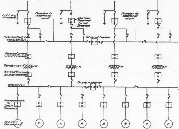 |
| Fig. 7 -- Schematic Diagram of Switch Connections. |
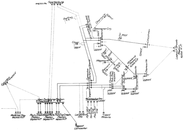 |
| Fig. 8 -- Diagram Showing Preset and Future Transmission Circuits. |
The low-tension bus and oil switch structure is built up of concrete slabs and steel framing. The oil switches are contained in the cells of the substructure, and the bus bars are carried in compartments built above these and around three sides. A gallery of structural steel and concrete provides accessibility for the operation of the selector switches. A sectionalizing oil circuit-breaker cuts the bus-bars into two sections, and by means of the selector switches mentioned each section may be further divided. It is therefore possible with this arrangement to operate in multiple the entire equipment, half of it or any pair of generators. Bus-bars are made up of five strips of copper clamped together, each strip being 1/4 in. x 3 ins. They are connected to the low-tension side of the transformer through automatic oil circuit-breakers, the connection consisting of two 1,000,000-cm lead-covered cables per phase.
Leads from the high-tension terminals of the transformers are taken through a well in the floor of the second story, where they connect through oil switches either to high-tension busbars or feed directly into the line. Here, again, flexibility of control is secured by an arrangement of selector switches, whereby any bank of transformers may be operated or thrown on the bus-bars for multiple operation. Current for operating all high-tension circuit-breakers is obtained from oil-insulated series transformers. All high-tension wires and bus-bars consist of 1-in. copper tubing. The selector switches and bus-bar insulators are supported on a steel structure of latticed girders.
In order partially to relieve the transformer winding of the excessive strain due to surges in the line, choke coils of the oil insulated type are placed between the transformers and their respective high-tension bus oil switches. The lightning arresters are of the single-pole, low-equivalent type, for which the manufacturers claim great efficiency both as to the prevention of rise of potential on the line and the suppression of the arc after the discharge. The complete electrical equipment was furnished by the Westinghouse Electrical & Manufacturing Co.
TRANSMISSION LINES.
At the present time electricity is transmitted from the Catawba station to Rock Hill, Charlotte and Fort Mill at 11,000 volts, on wooden poles. Upon the completion of the Great Falls station the line to Charlotte will be operated at 44,000 volts and will be extended to Concord, N. C., while an additional line to Gastonia will also be operated at the higher e. m. f. Temporarily, at least, the distributing point of the system will be the Catawba station, at which a transformer house is being erected to contain three 2000-kw 11,000 to 44,000-volt transformers for running the two stations in parallel, a trunk line supported on steel towers being built from Great Falls to the Catawba station. In the diagrammatic layout of the transmission system all solid lines are either in operation or under construction. The dotted lines indicate future installations. See Fig. 8.
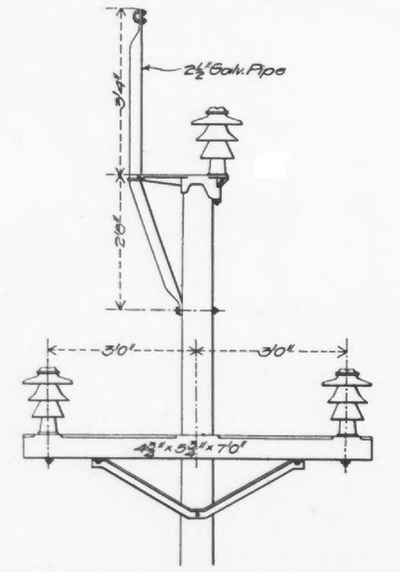
WOODEN POLES.
The present 44,000-volt transmission lines are being placed on two single-circuit wooden pole lines located side by side. A 35-ft. cypress pole is used to support each circuit of No. 2-0 six-strand hemp core cable. The three cables from approximately an equilateral triangle, whose sides are 6 ft. in length, two of them being supported on a cross arm and one on a special cast-iron bracket, which fits snugly over the top of the pole. Thomas insulators 13 in. high and 12 in. across the top and Locke insulators, 12 in. x 12 in., are used indiscriminately. With a view to meeting general adaptability a special insulator pin was designed. This consists essentially of a cast iron sleeve through which passes a bolt. A cast-iron bushing is cemented into the insulator and into this bushing the through bolt is screwed. By the use of such a pin, strength is assured and in broken insulators the bushing only is lost, while for whatever support it may be desired to use them on it is necessary merely to use a bolt of greater or lesser length. The cross arms are of long leaf yellow pine 4-3/4 in. x 5-3/4 in. x 7 ft. long dipped for 15 minutes in carbolineum avenarius at a temperature of 65 degrees C. The increase in the weight of the cross arm after having been subjected to the above treatment is about 4-1/2 per cent.
A lightning wire is supported by a 2-1/2-in. galvanized pipe flattened at each end. The pipe is fastened to the pole by means of the cast-iron bracket. See Fig. 10.
STEEL TOWERS.
The transmission scheme contemplates the eventual construction of a circuit trunk line into which all power stations shall feed, and on this circuit, at least, galvanized-steel towers are to be used throughout. These towers are designed for two circuits, each circuit having a ground wire placed above the highest transmission wire in such position that a line drawn through this ground wire and the upper transmission wire forms an angle of 60 degrees with the horizontal.
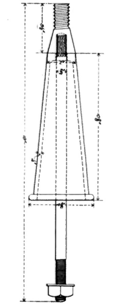 |
| Fig. 9 |
 |
| Fig. 10 |
A six-strand cable with hemp cord, the equivalent of No. 3-0 wire is used for the main conductor, and a solid iron wire is used for the ground conductor. The transmission wires are located at the corners of an equilateral triangle, the sides of which are 6 ft. in length. The towers also support a telephone line strung 27 ft. above the ground and passing through the center of the tower. The spacing of towers is approximately 420 ft., the average number per mile being twelve. Where the ground is moderately level a standard tower 35 ft. in height from the ground line to the lowest conductor is used, while for very uneven ground there have been provided two special height towers of 43 ft. and 50 ft., respectively. The 35-ft., 40-ft. and 50-ft. towers weigh 2400. 3000 and 3500 lbs., respectively, and are all of the same type of construction. The special towers were furnished by the U. S. Wind Engine & Pump Company, of Batavia, Ill., while the standard towers were supplied by the Aermotor Company, Chicago, Ill.
The towers are essentially twin towers, each half being joined to the other at a point midway between the base and the top of the tower proper. The 3 x 3-3/16-in. corner angles A frames, and are clamped together at a point 2-1/2 ft above the highest cross arms, while the two other main members, 3 x 3 x 1/8-in., of half of the tower, as viewed from the same point, form A frames at one-half the height of the tower, and riveted together. To these members is riveted a 3x3x3/16-in. third member, which is clamped to the corner angle at the top. Each half of the tower, therefore, has four main members from the ground to a point equal to one-half of the height and from this point up only three.
As viewed in the direction of the line the corner angles are upright with diagonals from the apex and from the base to' the center of the tower. All main members are securely held together by means of tie rods and angle iron struts. The two halves of the tower are joined together with a batten plate. The width of the base in the direction of the line is 13 ft. 2 in., while in the opposite direction it is 14 ft. 6 in.
 |
| Fig. 13-14 |
For each conductor there is provided a separate cross arm consisting of two 2-1/2 x 2-1/2 x 1/8-in. angles placed back to back, the pin end of each cross arm being braced to the tower by a 2-in. pipe. The insulator pins are made of standard 2-in. pipe drawn down at the top and threaded to take firm hold in the top of the insulator, into which they are cemented. A Thomas insulator with a special bottom petticoat is used. This insulator is 13 in. high, having a cap 12 in. in diameter.
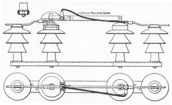
The line is suitably transposed and is sectionalized at each point of partial transposition. This combination of connections requires the use of four of the 12-ft. x 12-ft. towers with a special insulator flange bolted between the two pairs of towers. Five sets of selector switches are so arranged that a crossover from one circuit to the other may be effected and any section may be cut out for repairs in case of a breakdown. For outside work a special disconnecting switch has been designed, the insulators of which are mounted on a 5-in., 6-1/2-lb. channel and in place of the customarily used copper bar a steel bar is used. This has a copper contact and the circuit is made through a flexible cable.
The organization of the Southern Power Company was effected under a New Jersey charter with an authorized capital of $7,500,000. Of this amount $2,500,000 was set aside as preferred stock, yielding 7 per cent cumulative dividends, the remaining $5,000,000 being common stock. On Oct 24, 1906, the capital stock was increased to $10,000,000, the additional $2,500,000 apportioned to the preferred stock.
The property holdings for this entire development aggregate nearly 9,500 acres, much of which could not be leased for agricultural purposes, and on such land 750 pecan trees were planted, which in time are expected to bring good returns.
The officers of the Southern Power Company are; Dr. W. Gill Wylie, of New York, president; B. N. Duke, of New York, first vice-president; W. S. Lee, Jr., of Charlotte, N. C., second vice-president and chief engineer; R. B. Arrington, of New York, secretary and treasurer; L. C. Harrison, of Charlotte, assistant secretary; W. H. Martin, Jr., of Charlotte, assistant treasurer.
