[Trade Journal]
Publication: American Institute Of Electrical Engineers
New York, NY, United States
p. 1239-1257, col. 1
LIGHTNING-RODS AND GROUNDED CABLES AS A
MEANS OF PROTECTING TRANSMISSION LINES
AGAINST LIGHTNING
BY NORMAN ROWE
The following is practically a summary of lightning trouble during the years 1904, 1905, and 1906, on a steel-tower long-span transmission line in the states of Michoacan and Guanajuato, Mexico.
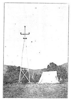
The main transmission line, built in 1903, was the first one constructed on steel towers. These towers were of standard type, the height being 40 ft. from the top of the cross-arm to the ground. Three wires were placed upon the towers in the form of an equilateral triangle, the upper wire being supported upon a 3-in. extra heavy pipe, which formed the continuation of the tower, the other two being placed at the ends of a double channel-iron cross-arm, approximately 7 ft. in length, the sides of the triangle being 6 ft. The insulators used were 12 in. high and 14 in. in diameter. These insulators were cemented directly on cast-iron pins. The pins for the top insulators were made to screw on the 3-in. pipe; those for the side insulators had a square shank and were secured to the cross-arm by two 1-in. bolts. The conductors were 19-strand, hard-drawn copper cable, equivalent to No. 1 B. &. S. solid copper wire. There were no wooden pins or cross-arms used on the towers. For protection against the line voltage as well as any high voltages to lightning discharges, dependence was placed entirely on the insulators.
The ordinary length of span was 440 ft., but there were several spans of 1200 ft. and one of approximately 1600 ft. The line was designed for 60,000 volts at the generating end and 51,000 at the receiving end. The length of the line was approximately 101 miles.
The line is tapped at Irapuato, approximately 75 miles from the generating station and. 26 miles front Guanajuato. At this point there is a sub-station where lightning-arresters of the usual station type are installed to protect the step-down transformers. From this it will be seen that there is a chance for the line to discharge at this point as well as over the arresters at either end of the transmission line.
| |||
| Fig. 1 Showing Line As Originally Constructed. |
Thus far there have been three rainy seasons, which in the part of Mexico where the line is situated, generally last from June until October. Heavy thunderstorms come up nearly every day during July and August, and there is a storm on an average of every two days through a period of four months. During the rainy season of 1904, there was considerable trouble with lightning; the next season there was less, and during the rainy season of 1906 comparatively little trouble was experienced. The nature of the troubles, the expedients tried to overcome them, and the provisions for overcoming future lightning troubles will now be considered.
The rainy season of 1904 came on with great severity in April, two months earlier than usual, and lasted until October. The injury to the transmission line from lightning was mostly continued to the puncturing of the top insulators by direct bolts of lightning, and in most cases a hole was bored through the top insulator nearly in a vertical line to the pin. These holes were approximately one inch in diameter and the sides were glazed. Usually, the insulators were badly shattered, but on putting the parts together one could generally find the glazed hole above referred to. Some side insulators were lost, but they were almost invariably injured at the time when the top insulators on the same or adjacent towers were injured. The side insulators were never punctured from the top in a vertical direction, but in some cases they showed a small puncture in a horizontal direction from the tie-wire to the pin. In nine cases out of ten, however, they were not punctured at all, but half of the top and portions of one or both petticoats on the same side were broken, presumably by the power current following lightning discharges over their surfaces.
| |||
| Fig. 2 Showing First Change. Top Insulator Lowered, Grounded Cable in Place, and Lightning-Rods Left in Position. |
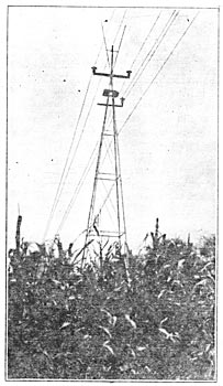
As the principal trouble apparently came from direct bolts of lightning striking the top insulators, it was thought advisable to erect lightning-rods on the towers on the section of the line where most trouble had occurred. At that time the placing of a grounded cable over the transmission wires was discussed, but as this could not be done before the end of the rainy season, for suitable material could not be obtained in Mexico, it was decided to put up lightning-rods and get the benefit of experience with them during the rainy season then in progress.
Lightning-rods were erected in pairs starting from the 3-in. pipe at the point where the cross-arm in pairs was attached, and projecting up on either side of this pipe to a distance of 6 ft. above the top insulator at an angle of about 30 degrees from the vertical.
By the middle of August one-half of the line giving the most trouble was equipped with lightning-rods, and there had been erected quite a few rods on towers that were considered as being particularly exposed to danger from lightning. After the erection of these rods the difficulties were very much less. although there was still some trouble on the section of the line where they were in place. In no case were top insulators punctured through from the top as on the towers where rods were not in place, but when insulators were injured they usually had a part of the top and a petticoat broken on the same side. There were also a few cases where insulators were punctured in a horizontal direction from the tie-wire to the pin. During one very severe storm, eight insulators were broken on seven towers spread out over a distance of 14 towers. As the towers were spaced 12 to the mile it is improbable that the same discharge of lightning could have caused all of this trouble, unless it was transmitted over the power lines. Of the eight insulators injured none was punctured; they were apparently damaged by the current going over their side. Although these insulators were badly injured, the service on them was continued, but at a slightly reduced voltage.
One quite remarkable case happened in the Guanajuato substation, due, perhaps, to a bolt of lightning striking the line about a mile away. One of the men was standing in a balcony in Guanajuato watching the lightning display, when apparently a very heavy discharge struck the tower line, located over a hill just out of sight. At the same moment the lights in the room went out, showing that the service had been interrupted. The lightning which caused this interruption of service came into the sub-station over the top wire and jumped 4.5 ft. through air to ground, at the same time going to ground over the lightning-arresters. An insulator over which the arc formed in the sub-station had half of the top cracked off, but no injury was done to the transformers or other equipment. The towers were carefully examined near where the lightning was seen to fall, but there were no broken insulators or other evidence to show that the bolt had struck the line. However, as lightning had been previously seen to strike the towers without causing trouble, it was thought that a bolt of lightning had struck the tower line, a portion of this discharge coming over the wires into the sub-station. At the place where the bolt was supposed to have struck, the towers, on exposed places, were equipped with lightning-rods.
These cases are cited to show that insulators at a distance from heavy discharges of lightning may be subjected to very severe voltages, and, from all the data at hand, it is believed that the lightning-rods were efficient in protecting the insulators from direct bolts of lightning, and that the trouble that was still present on the section of the line equipped with lightning-rods was due to discharges traveling along the transmission wires.
During the season of 1904, the line troubles were quite evenly distributed over the first 50 miles of line out of the generating station. There were only two cases of trouble outside of this section that caused injury to the line insulators. Equipping this section with lightning-rods was begun in June and finished in August. This section of the line, except for a stretch of 15 miles, was left as equipped in August, 1904, until October, 1906, or through more than two lightning seasons. As there was less trouble on this section of the line during these two seasons than during a portion of the lightning season of 1904, it is evident that the lightning-rods were at least partly effective.
| |||
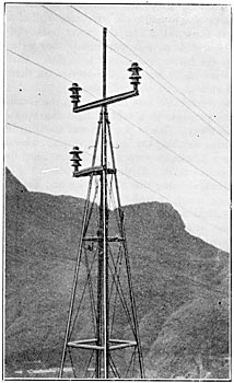
| Fig. 3 Showing Present Appearance of Line. Lightning-Rods Removed. |
After finding that lightning-rods were not a complete protection, it was decided to make the experiment of lowering the top wire and putting up a grounded cable in its place. However, on account of delay in receiving material, very little was accomplished in time for the rainy season of 1905 and the experience with lightning during that season was the same as that obtained during the rainy season of the previous year, except that there was much less trouble.
In the winter of 1905-1906, it was decided to install larger insulators on the tower line and at the same time to lower all of the top cable to a position below one of the original side insulators. On the highest point of the tower, in place of the top transmission cable, it was decided to string over the entire line a 1/4-in. 7-strand steel cable, grounded at each tower. Insulators 17 1/2 in. in diameter, 20 in. high, were adopted for the first 60 miles of line out of the generating- station, and the same insulator with a 14-in. top for the other 40 miles of line. It was unfortunate that the insulators with the 17 1/2-in. top were not ready so as to complete the line changes in time for the rains, but half of the line out of the Guanajuato sub-station was finished before the time for severe lightning storms had arrived. The other half of the line had been equipped the first year with lightning-rods, which welt still in place, the top cable being in its original position on this section, except for a distance of 15 miles.
During the rainy season of 1906, the transformers were connected in star on the high-tension side, the center of the star being grounded, and in order to detect instantly when there was a ground on the line, a series transformer was put into this grounded line and the secondary leads carried to the switchboard, where an ammeter was connected to them. With this arrangement, when an insulator broke down, or the power current followed the lightning over the insulator, the station operator could tell when there was a ground on the line, and, by shutting down at once, he was able to prevent the burning off of the transmission wire. Usually, when a ground appeared and the power was cut off, the line was found in good condition on again starting up.
| |||
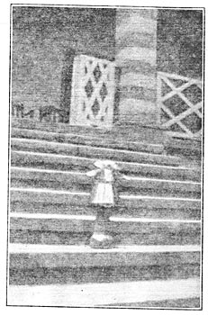
| Fig. 4 Insulator Perforated and Broken by Lightning Bolt. |
There was no apparent trouble from lightning during the rainy season of 1906 on the section where the grounded cable was in place. On several occasions grounds came on the lines during lightning storms, and the power was immediately cut off in order to clear them. In general: these grounds could not be located, so it cannot be said that lightning did not go over the surface of the insulators on the section where the grounded cable was in place. The section where there was no grounded cable in place, but where the lightning-rods were erected, still gave some trouble, but the total amount was much less than in any preceding year.
The part of the line found to be the hardest to protect during all three rainy seasons was the middle of the 75-mile section from the generating station to Irapuato; in other words, the part of the line farthest from the location of lightning-arresters. This would indicate that arresters for discharging the line, located say every 25 miles, would be a valuable protection.
The experience of the last three seasons prompts the writer to offer the following suggestions:
1. Insulators should not be disposed upon poles or towers so that they will be in the path of bolts of lightning going to ground by the supporting structure.
2. A grounded cable, strung above the transmission wires at highest point of the tower, is certainly more effective than lightning-rods in protecting the insulators and conductors from direct bolts of lightning.
3. Lightning-arresters, for discharging the line in case very high voltages are present on the wires, would be of some value if located along the line at frequent intervals.
4. On steel construction, an insulator should be used that has a high margin of safety against puncture and arcing over.
It seems at present general practice to use insulators for high potentials with practically no margin of safety, and when the conditions are severe there is almost sure to be trouble. Aside from trouble with the puncturing of line insulators by direct bolts of lightning, which was apparently prevented by the use of lightning-rods on towers, nearly, if not quite all, of the trouble on this line has come from the breaking down of insulators by the current going over their sides, or through them, from tie-wire to pin. The writer ventures to assert that, if the insulators had been much better, there would have been little trouble on the line where the lightning-rods were in place. Moreover, as a grounded cable undoubtedly affords better protection than lightning-rods, with a suitable grounded cable strung over the transmission wires, and better insulators so disposed as to be out of the path of direct bolts of lightning, even without the installation of lightning-arresters along the line there would result a line that should be practically free from lightning troubles.
NOTE.While personal experience suggests that the use, on iron construction, of insulators with a high factor of safety will greatly reduce troubles from lightning, it was decided to change our line insulators on account of trouble from an entirely different cause. During some months of the year the insulators become covered with condensed moisture just at sunrise, due to a very sudden rise in temperature, from the temperature of about zero centigrade. This often left insulators, on the portion of the line where the temperature variation was most severe, covered with condensed moisture nearly as heavy as hoar-frost, and, during the few moments when this effect lasted, the power current was apt to arc over the surfaces of the insulators. The old insulators were by the company's engineers as the best obtainable in 1902, and the insulators decided upon in January, 1906, were the largest commercial insulators on the market. A very much better insulator was desired, but for want of time to develop something better it was necessary to adopt an insulator with a factor of safety somewhat lower than that intended to be used. The apparent freedom from lightning trouble on the part of the line equipped with larger insulators and grounded conductor is due perhaps as much to the use of better insulators as to the grounded cable.
DISCUSSION ON "TRANSMISSION LINE TOWERS AND ECONOMICAL SPANS" AND "LIGHTNING-RODS AND GROUNDED CABLES AS A MEANS OF PROTECTING TRANSMISSION LINES AGAINST LIGHTNING," AT NIAGARA FALLS, N. Y., JUNE 26, 1907.
William Hoopes: The method of treatment of this problem appears so excellent that one is at once interested in its practical application. The first conclusion reached is that the economical span-length is determined, not by the original cost of the line, but by its annual cost.
The annual cost is made up of three items:
1. Interest and depreciation on the first cost.
2. The cost of repairs and patrolling.
3. The money damage from interruptions to the service.
If lengthening the span will reduce the number of interruptions and cost of repairs, then the economical span is longer than that which gives the lowest first cost.
Inquiry into the operation of a large number of transmission lines reveals the fact that by far the larger portion of the interruptions of service is due to trouble occurring at the point of support; this applies particularly to steel-tower lines. Reduction of the number of supports does, therefore, reduce the annual cost.
The paper shows that this particular line on 800-ft. spans would cost about $300 more per mile than if on 400-ft. spans. Interest and depreciation on this at 10% would be $30 per year. Halving the number of supports would probably save much more than this.
I believe the subject has not been treated in this way in this or any other paper, so I should like to suggest to the committee that such a paper would open up a very live topic.
However, the province of Mr. Scholes' paper is really to show the least first cost of the line, and the above remarks are not strictly germane to it. Investigation of its practical application leads to the following queries:
1. Is the assumption of a uniform price per pound justifiable?
2. Does the retention of the same geometrical figure permit the design of all the towers for the least cost?
3. It is fair to assume that large foundations for higher towers cost as much per cubic yard as small foundations for low towers.
The cost of a tower to the purchaser is made up of the following items:
1. Cost of steel and transportation.
2. Cost of shop work.
3. Cost of galvanizing.
4. Cost of erection.
5. Manufacturer's profit.
If the cost of the tower is directly proportional to the weight of the steel, then all of the items of cost must vary at the same rate as the weight. The cost of the steel does vary approximately as the weight.
The paper gives the cost of a 34.5-ft. tower as $30, and of a 70.5-ft. tower as $243, which is about proportional to the cubes of the heights. The other costs should therefore be as the cubes of the heights.
Inquiry from a concern which makes a very large number of towers elicited the following. opinions:
1. As the number of parts is the same for large as for small towers, the number of shop operations will be about the same; but as the shop operations will be slower on the heavier work, the shop cost will vary about as the height of the tower.
2. The same opinion was expressed with regard to the cost of erection.
3. The galvanizing cost is approximately proportional to the superficial area, _or to the square of the height. The galvanizing was said to be a very material portion of the whole cost.
When it came to a question of manufacturer's profit the source of my information ran dry, but if it increases as the cube of the height, it would seem to afford a considerable opportunity to a resourceful purchasing agent.
From the foregoing it would seem that all the costs which go to make up the cost of the tower, other than the cost of steel, vary at a less rate than the cost of the steel, and that a smaller price per pound should be used in determining the cost of the large towers than is used for the small towers.
It would add to the value of Mr. Scholes' paper if he would answer my three questions, and I should like to ask further if it is actually possible to furnish a 34.5-ft. tower galvanized, for $30? or a 32-ft. tower for $21? the prices given in the paper.
P. H. Thomas: Mr. Rowe has given us valuable data on the effectiveness of the overhead ground-wire for protecting high transmission lines. The only thing that remains is to draw correct inferences from the data, and that is very difficult to do. There are some salient points, however, which seem to indicate the real lesson of the paper.
In the first place, in judging of the performance of a new line, the necessary elimination of weak insulators which occurs during the early operation must be taken into account. Mr. Rowe says that by the use of a series transformer in the ground connection he has discovered a way to get the current off the line quickly enough not to break the insulators, so that the power could be thrown directly back again. This is an important point to consider, for if that is the way the improved operation was brought about it is no credit to the overhead grounded conductor.
Mr. Rowe says further:
On several occasions grounds came on the lines during lightning storms and the power was immediately cut off in order to clear them. In general, these grounds could not be located, so it cannot be said that lightning did not go over the surface of the insulators on the section where the grounded cable was in place.
This apparently indicates that, only improvement resulted from the grounded wire.
Furthermore, in addition to the installation of the grounded cable, there was a change in the size of the insulators, largely on that part of the line protected by the overhead cable. This, in itself, is the very best sort of lightning protection. As Mr. Rowe himself intimates that the original insulators were really too small for their work, it will not be safe to infer too much from the increased satisfaction in the operation after the introduction of the grounded overhead conductors. On the other hand, it is probably certain that the overhead grounded conductor does relieve the line insulation a great deal; especially in the way of reducing the severity of the heaviest strains.
Is it not true that too great a risk is being taken in using steel poles, steel cross-arms and pins, relying wholly on the insulator? It is relatively easy for a charge to pass over the insulator's surface to ground at the pin, and it is usually destructive when it does come, starting an arc to ground which breaks the insulator and tends to shut down the plant. Is there not some way to preserve the advantage of the old wooden pin and cross-arm, which prevented many discharges to ground from becoming short-circuits?
W. S. Lee: As Mr. Hoopes has suggested, we should not try to get too economical a tower or too economical a span. In some cases these transmission lines are carried over a rolling country; in other cases over a flat country with no fall for a water power, so we have to span from hill to hill, and from point to point, and the practical erection of the line means irregular spans. We have found that in our service. Now, while one may figure on a fixed-span tower, the chances are that the spans will be regulated by the topographical conditions. The usual practice is to make a profile of the country. If there is to be a tower for a 400-ft. span, and the next span has to be extended to 550 feet or 650 feet, we would need towers of different strength. It would be best to keep the tower standard on the line, in case of repairs, or shipments of parts; and for that reason I would suggest getting stronger towers which could be used for either long or short spans.
Referring to Mr. Rowe's paper: In 1897 I was with the Anderson Water Light & Power Co., Anderson, S. C., and we built an 11,000-volt line for a distance of 10 miles. While the poles were being constructed, and before there was a wire strung on them, two poles at different points were shattered entirely by lightning. The plant was built and has been in operation since that time; it has two lines of barbed wire overhead. Though there has been some trouble with lightning, they have not had a direct stroke of lightning on that line since that time. . The Catawba Power Company, of Charlotte, N. C., has a transmission system of 18 miles. When the line was built in 1904 one pole was struck by lightning, but there was no wire on it. There is one grounded wire overhead, and no pole has been damaged by lightning since that time, nor has there been a direct bolt of lightning.
We built in 1905 at this same station, a line 20 miles long. It had 11,000-volt service, built with 40,000-volt insulators. This was a three-phase, single-circuit line, and in order to arrange for equilateral triangle construction one wire was placed on top of the pole. We endeavored to locate a grounded wire above the apex wire, by extending supports up to this point, and curving them so as to keep away from the apex wire. This arrangement did not work. We found that irregularities in the country resulted in a tendency to pull up or down, in some cases to bring the grounded wire close to the apex power-wire. For this reason the grounded wire was left off this circuit. Since 1904, there have been two direct strokes of lightning on this particular circuit; neither stroke interrupted the service, but both damaged poles by splitting them. All the lines are now being equipped with the overhead grounded wire.
F. B. H. Paine: Mr. Thomas suggested a question which is frequently asked, in view of our extended use of steel poles and towers; whether we are not putting too much trust in the insulator, and would we not do better with the added insulation of pole, cross-arm, and pin? For a good while I was in doubt about it, but after an experience of two years I think that Mr. Mershon's judgment has been amply sustained. I have recently visited many transmission plants, and in every instance I found that the annual destruction of poles and cross-arms, that is, the entire destruction of the supporting structure, exceeded our loss of insulators per mile. We can replace the insulators much quicker and cheaper than we can the entire supporting structure, whether it be of wood, steel, or what-not. We have something like 200 miles of 60,000-volt transmission lines on wooden structures using the same insulators cemented on steel pins, the steel pins being carefully grounded. We have had some terrific lightning disturbances in that section, and, although many insulators have been lost, in no instance has any injury come to the wooden structure on account of the pins being grounded, and to all intents the same condition existed as on the steel tower or steel pole. I think we have answered the question as to the desirability of wood as an insulator for high-voltage lines very effectively use metal pins, ground them, and save the pole and cross-arm.
C. W. Ricker: The experience of a railway transmission line in western Ohio may be of interest. This consists of about 100 miles of three-phase, 3300-volt line built in 1901 on wooden poles with wooden cross-arms and porcelain insulators designed for use at that voltage by one of the largest American makers. Each cross-arm had two steel braces applied in the usual way, and the insulators are set on steel bolt pins about 9 in. long. The line runs through a country in which lightning storms are frequent but not exceptionally severe. Interruptions of service have occurred during thunder storms, and usually two insulators on the opposite ends of the same arm would be found punctured from the tie-wire to the pin. The interruptions became so frequent that it was necessary to make some change, which had to be done without disturbing the working of the line; this left about two hours each night available for work, and the owners of the line were not prepared to incur any heavy expenses. Accordingly, half the cross-arm braces were removed, leaving on each pole a brace from the pole to one end of the cross-arm only, and wooden pins about 15-in. long were substituted for the steel pins, using the same insulators.
After this change the interruptions of service due to lightning were diminished from an average of two or more a month to about the same number during the season following the change. Several cross-arms were burned off, but caused no suspension of service at that time.
Geo. T. Fielding, Jr.: Incidental to the main subject of Mr. Scholes' paper, I would like to arouse some discussion on one of his assumptions: namely, that of allowing for one-half inch of sleet upon the conductor. As a matter of common interest, it would be profitable to learn if any one here has ever seen sleet upon a transmission line that was carrying power or even charging current, and also if there was any wind at the time this occurred. This is an old question perhaps, but we have had experience enough now to cease basing calculations upon advance assumptions that were made for the first lines erected. The greatest mechanical stresses on transmission lines are due to high winds, and a small increase in the diameter of the conductor, as occasioned by a coating of sleet, results in a considerable increase in the imposed stress. The assumptions made, as regards sleet, therefore very materially influence the allow able sags and tower-heights, and while it is legitimate to favor conservatism, it is questionable if we are not inclined to be over-liberal.
I notice that Mr. Rowe uses a stranded steel cable for the ground-wire. This has been the practice on a number of lines. On account of its short life and tendency to stretch and sag, one of the larger telegraph companies has recently ceased using stranded cable for guy- and messenger-wire service. The old solid No. 3 steel galvanized wire is now being substituted in its place. It seems quite reasonable that the cable should tend to retain moisture, by virtue of its strands, and hemp center if it has any. This moisture is not helpful in preserving the metal against rust.
Mr. Rowe seems to have had considerable trouble with puncturing of the insulators. This experience has been repeated on many other transmissions. On steel-tower lines where disturbances cause local and suddenly excessive potentials or frequency, the insulators are often observed to puncture before they will arc over, due probably to the clement of time which is necessary for the potential to distribute itself.
Increasing the thickness of porcelain does but very little toward increasing its resistance to puncture. It appears as if the use of larger insulators is not the solution of the problem; that is, it is not enough simply to install insulators of larger dimensions, insuring merely a greater arc-over capacity. It is essential to separate the live conductor and the ground, the pin, by a greater distance than has heretofore been specified to obtain reliable insulation: this has been accomplished by the suspension method, described in the paper by Mr. Hewlett. We shall be compelled to direct our efforts with this principle in view before we can successfully operate at, or above, 100,000 volts.
N. J. Neall: One point in Mr. Rowe's paper is, in my judgment, misleading; that is, the use of a circuit-breaker attachment in the neutral of the transformers. In any three-phase transmission line with grounded neutral, the puncture of even a single insulator is more than likely to result in the fusing apart of the conductors, so that in this particular instance any disturbance of this character would undoubtedly seriously impair the continuity of service. I have seen this fusing take place in surprisingly quick time and realize perfectly what it means on service. Now the conclusion to be drawn from Mr. Rowe's paper is that the additional line protective apparatus, irrespective of the automatic cut-out, has been the chief benefactor in this case, but this seems to me a very doubtful conclusion. In other words, the important result is that a combination of these things--overhead ground protection, larger insulators, and automatic cut-outs, has produced the desired improvement.
Ralph D. Mershon: The assumptions as to sleet, wind, and various other things which should be taken care of in the design of a transmission line are questions on which engineers will differ almost as much as on the subject of the use or non-use of choke coils. It seems to me that the general solution presented by Mr. Scholes is a very admirable and satisfactory one. There are some points in it to which exception might be taken, but if all the refinements are gone into, such general solution would become so complicated that its value would be questionable. The value of this general solution is that by sorting general assumptions, one can arrive at a preliminary idea as to what is going to be the best plan, considered from the standpoint of those assumptions, and that this preliminary idea will serve as a guide in adapting the construction to meet other considerations, such as inequalities of the country, the desirability of having fewer points of support, etc.
I shall be interested to hear from Mr. Scholes as to the cost in proportion to weight.
Mr. Rowe's experience with grounded wires does not enlighten me much. It does not seem to me that he has offered any definite evidence that the grounded wires do a great amount of good. In the plant of the Niagara, Lockport and Ontario Power Company, we are trying to avoid the use of the grounded wire on account of the expense of putting it up. We are installing on the top cablethere are only three cables, carried on the tower in the form of an equilateral trianglewhat amounts to a horn lightning-arrester, a grounded horn reaching far enough above the tower to serve also as a lightning-rod. During the last few days we have had worse storms than we had last year, and the results, so far as we have been able to analyze them, seem to show that these line structure lightning-arresters, as we call them, have been of great value. Their value could be greatly augmented by increasing their number. They are now spaced at approximately 2200 ft., and are set for a discharge gap of 6 in. This discharge gap will be reduced to 4.5 in. or, perhaps, even to 4 in.
Some of our experiences seem to show that lightning does not travel along the line. During one of the storms the last two or three days, we have had three insulators punctured between two of the line structure lightning-arresters. The lightning chose to puncture an insulator rather than travel 550 ft. to go over the 6-in. gap. Possibly, when we reduce the size of the gap, we can cause the lightning to travel.
I am not much of a believer in the idea of being able to foretell what is going to happen in the matter of lightning, whether the prediction involves the nature and contour of the country or the apparatus concerned. We now have, I believe, about 400 miles of main line; 80 miles of this is in rough country, the rest of it is over country that is practically flat. In the flat country the lightning is at times perfectly fiendish, so that, if there is any connection between lightning and mountains, there is nothing on our transmission line to indicate that such is the case.
We do not transpose our lines. We had some transpositions, but found they could be taken out, and have taken out almost all of them. We intend to confine the line structure lightning-arresters to the top wire, in order that when it operates our service will not be interrupted; since, if there are line structure lightning-arresters on two or more of the cables, and two of them operate simultaneously, a short-circuit will result. Whereas, if the lightning-arresters are confined to one of the cables, and we have a resistance in the neutral of the generating station, the arc will clear itself without necessarily interrupting the service. If we transpose and endeavor to follow out this idea, the line structure lightning-arresters would have to be, in some instances, on the top cable and in some instances on one or the other of the cross-arm cables. It may be that: before we get through, we shall put line structure lightning-arresters on more than one cable; but, judging from the performance of the line structure lightning-arresters with a 6-in. gap and spaced 2200 ft. apart, as is the case at present, this will not be necessary. In the last three severe storms, one of which was worse than anything we ever had before, the present installation of line structure lightning-arresters has done much good.
The sub-station lightning-arrester equipment is the one which Mr. Stott has designated as the "totem-pole" equipment. There are nine horn lightning-arresters to each three-phase circuit, three to each conductor of the three-phase circuit. One of the three is set for a large gap and high resistance, the next for a higher gap and lower resistance, and the next for a still higher gap and that has a fuse. So far these arresters have afforded full protection. They have discharged frequently. There are no choke-coils.
N. J. Neall: In your line arresters do you get a continued arc because of the resistance in the neutral, or is it the customary charging arc which you get if you ground one leg of the railway system?
Ralph D. Mershon: We have the neutral grounded through a resistance, and think the line arresters will behave in a good deal the same way as the intermediate arrester used at a sub-station having an intermediate gap, and which has 1000 ohms in series with it.
D. R. Scholes: it must be borne in mind, in considering this problem, that it is impossible to choose a single set of assumptions which will be satisfactory for all lines. Varying climate, contour of country, and other varying conditions of this nature make it impossible. The making of such assumptions in the paper is incidental to the main object of the paper.
It is to be observed that the method pursued in the paper is first to derive an equation expressing the relation between the weight of a tower of given design and its height and strength. This expression is almost wholly accurate. An example illustrating its application to a practical case is then giver. In the example certain assumptions are made use of. It is expected that such assumptions will, in each case, be made to suit the particular conditions that are being dealt with.
Most of the discussion, however, has had reference to these assumptions, and while it is not important that their accuracy be proved, the following may be said in support of them: It is assumed that the towers may be had at a given price per pound. This may not always be the case, but, within the range of ordinary practice, manufacturers are to be found who will contract for such structures at a given price per pound, before the size or strength of the towers has been definitely fixed.
It is assumed that the cost of a foundation will vary directly as its volume. The foundation cost will, of course, largely depend on the local conditions. Inasmuch, however, as the economical span will almost always be between 400 and 800 ft., and since the size of the foundation required will not change greatly between these limits, such an assumption seems admissible in the present instance.
The builder of steel towers for transmission lines is apt to find that the variety of assumptions regarding wind, sleet, factor-of-safety, etc., with which he has to deal is almost as great as the number of different engineers with whom he comes in contact. Each engineer seems to have a different set of natural conditions to meet. The severity of his assumptions seems to depend, generally, on how much money his company can afford to spend on towers. Now it is manifestly impossible to give mathematical expression, in advance, to factors which vary from causes of this sort. So the paper aims to put in the hands of the engineer in charge of line construction a formula which will show the effect on the tower-cost of any change in assumption he may contemplate, and which will make possible a simple solution for the economical span on the basis of his own assumptions.
Frank G. Baum (by letter): Mr. Scholes finds a shorter span more economical than is generally supposed to be the case. It would be of interest had he drawn two curves showing the cost of tower structures, one using his assumptions of sleet or snow on the cable at time of maximum wind velocity, the other with no sleet or snow. In a large section of the country sleet and snow need not be taken into account in the calculations.
Farley Osgood (by letter): Will Mr. Rowe please say whether with complete overhead grounded wire and lightning-rod installation, the use of time-limit relays on the outgoing transmission lines, is recommended, or whether instantaneous relays are preferred?
It is believed that a lightning-arrester installation about 75 miles from the power-station would help the system to a considerable degree, especially if the proper type of electrolytic arrester is used, which has been proved to he very efficient in cutting off the crests of surge-waves.
Would Mr. Rowe recommend the use of an overhead grounded wire on a wooden pole line, to be grounded at every pole by a suitable ground wire running down the pole?
