[Trade Journal]
Publication: The Journal of Electricity, Power and Gas
San Francisco, CA, United States
vol. 18, no. 23, p. 435-442, col. 1-2
Kern River Station No. 1 of the Los Angeles Edison Electric Company
(Continued from June 1.)
Owing to the nature of the mountain where the tunnel emerges above the power ‘house, no terminal reservoir could be excavated, so a fore-bay, 30x40 feet, was cut to a necessary depth below the grade of the supply tunnel, with controlling gates, and screens over the mouth of the force main.
Retaining walls were made of sufficient height to prevent material from the mountain above, from entering the: fore- bay. On the lower side where the wall was un- supported it was made sufficiently heavy to with- stand the water pressure on the inside of the fore-bay. The water enters the force main from the bottom of the fore-bay from opposite directions, thus preventing any formation of eddy or whirlpool currents.
| |||
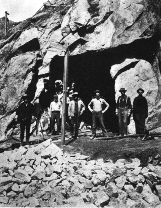
| Portal of Tunnel No. 5, Kern River. |
A spillway, the height of which can be controlled by means of flash boards, was constructed on one side, leading to the waste conduit, extending down the mountain side and discharges into the Kern River, 600 feet above the power station. This conduit is of concrete at the upper end, and terminates in a red- wood flume down the 45 deg. grade of the hill.
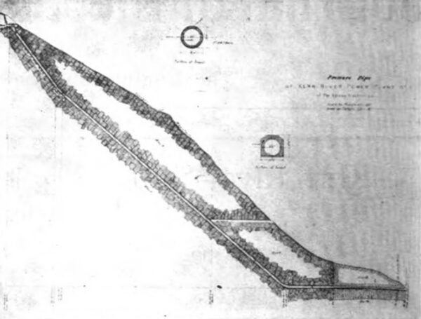
The construction of the force main is the most unique and interesting piece of engineering in the system. Instead of laying steel pipe on the surface or burying it only deep enough to prevent external injury, it consists of an incline tunnel driven through the mountain. This tunnel begins in the bottom of the fore-bay, and runs through the cline tunnel driven through the mountain, as shown by the cut, and emerges at the lower end on a level with the floor of the power house station.
The force main starts with a diameter of 9 feet, tapering or 20 feet to a diameter of 7-1/2 feet, which it maintains for 1,172.3 feet. At this point the force main tunnel emerges from solid rock to a detrital deposit lying between the mountain and the power house, through which a tunnel was driven to its emergence at the power house, a distance of 252.7 feet.
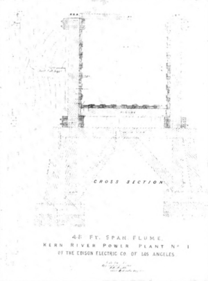 |
| Flume Cross Section. |
The upper end of the tunnel in the solid rock was lined with steel plates, 3-16 inch thick, riveted together in the form of pipe 7-1/2 feet inside diameter. The steel pipe was put in 10-inch sections, the space between the steel pipe and rock being filled with a mixture of concrete, three parts sand, three parts crushed rock, and one part Portland cement. The installation of this lining was begun at the lower end where it passes through the 252.1 feet of detritus, at which point a taper of 1-1/8-in. steel plate, to withstand the static pressure without external support. No concrete was placed around this pipe, and the terminal was left with the timber sets to support the ground over-head.
| |||
| Pressure Pipe of Kern River Power Plant No. 1. |
The steel plate was riveted together with both straps placed in solid rock, reducing the diameter from 7-1/2 feet to 5-1/4 feet.
From the end of this section of pipe the header pipe was run, with the following lengths and diameters:
For 33.5 feet, 4-3/4 feet pipe; for 23 feet, 4-1/4 feet pipe; for 21 feet, 3-3/4 feet pipe; for 11.5 feet, 3 feet pipe; for 16.7 feet, 2 1-3 feet pipe at end.
These diameters are graduated to maintain uniform velocity after withdrawing the water in various branches to supply the water wheel units in the power house.
In reducing the force main at its various pipes to meet — the diameters given, taper pipes as follows were used:
I taper 7.5 ft. diam. to 5.25 in. diam. 20 ft. length
I taper 5.25 ft. diam. to 4.75 in. diam. 10 ft. length
1 taper 4.75 ft. diam. to 4.25 in. diam. 10 ft. length
1 taper 4.25 ft. diam. to 3.75 in. diam. 10 ft. length
I taper 3.75 ft. diam. to 3.00 in. diam. 10 ft. length
1 taper 3.00 ft. diam. to 2.33 in. diam. 10 ft. length
From the force main, the branches were taken out at right angles to the rear wall by means of a Y on the header pipe. Each branch for the water wheels has 28-inch inside diameter, and each branch for the exciters has a diameter of 10 inches.
The water is projected on the buckets of the be wheels through deflecting nozzles with needle valves by means of which the discharge of the tip can be regulated without disturbing the form of the jet.
There are eight impulse wheels, each having eighteen 27-1/2-inch buckets bolted to the rim. One wheel is mounted on each side of the generator.
The four big impulse wheels which convert hydraulic to electrical energy, have each a capacity of 10,750 horse- power at full gate, and a speed of 250 revolutions per minute, when operating under a net effective head of 865 feet. In addition to the main turbines there are two exciter turbines, also of Allis-Chalmers design, each with a capacity of 450 horsepower, and a speed of 430 revolutions per minute.
Automatic regulation is effected by means of oil-operated hydraulic governors.
The combined moment of inertia of the revolving element in the water wheels and generator is 1,800,000 ft. sq. Ibs. by means of which regulation at 100 per cent load variation is obtained within less than 8 per cent when the units are carrying 50 per cent overload and within less than 5- 1/3 per cent variation of speed when running at normal load.
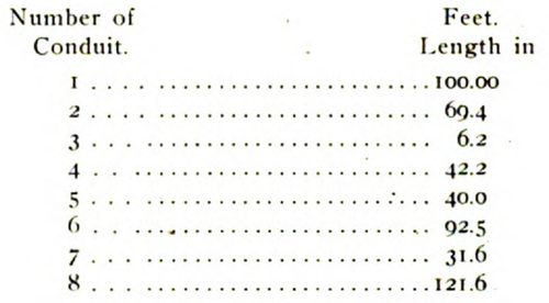
There are a number of concrete conduits connecting some of the tunnels and flumes. The interiors of these conduits are of the same dimension as the flumes. They are made of reinforced concrete with steel arches, covered with a cushion of earthen material to receive the impact of any- thing rolling or sliding down the hill and passing over the conduit.
The following table gives the number and length of each conduit:
 |
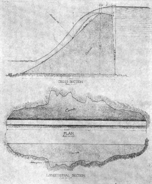
The concrete which entered largely into the construction of this plant was made from one part by volume of hydraulic cement, five parts broken stone, and three parts of sand. The broken stone, crushed to pass through a 2-inch ring, was made from tunnel waste deposited at the portal of each tunnel, and as there was little sand in the river, nine- tenths of the sand was made from the tunnel waste by passing crushed rock through sand rolls. The concrete was mixed by power mixers at the tunnel portals.
A construction plant, generating 300 kilowatts, was in- stalled for furnishing power for driving tunnels, mixing concrete, transporting materials, also for lighting the swears and camp quarters.
This construction plant was developed by means of a flume 800 feet in length, supplying water to McCormick reaction turbines, operating one 150-kilowatt generator for each turbine. It was abandoned after the completion of the main plant.
All the methods of construction were among the most modern of engineering practice. As has been said before, electric power was used for handling the concrete, for lighting, and for compressing air.
The normal rated capacity of the plant is 20,000 kilowatts, or 26,667 electrical horsepower. The machinery is all tested to operate under 50 per cent overload for peak load service, thus making the ultimate capacity 30,000 kilowatts, or 40,000 electrical horsepower.
The space chosen as the power house site was directly in front of the point where the pressure tunnel emerges from the hill-side, at an elevation of 1061.95 feet. This point was chosen in order that the elevation of the pipe line and of the water wheels be sufficiently high to permit the running of the units when the Kern River was at its maximum flood.
| |||
| Cylinders Controlling Gates |
The foundations were started on bed-rock and cemented boulders, low enough to avoid any possibility of the power house being undercut by floods, and were carried up as walls in such a manner that no important machinery rested on floors placed on back-fill. Back-fill from other portions of the work was used to fill spaces between these walls which could not be utilized on account of their falling so low as to be subject to floods.
A deep excavation in the hill-side had to be made to accommodate the inner end of the building, the debris from this cut and from the tail-races was wasted on one side of the building as a dump. Upon this dump was placed a continuation of the pressure line from the machine’s Y, and on the other side the spoil-bank was thrown as a bulkhead to protect the power house against possible flood.
| |||
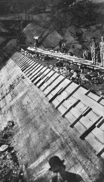
| Constructing Dam |
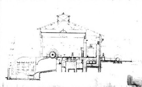
A small amount of reinforcement is carried upon the upper part of the machine foundations. The large masonry block back of each water wheel deflector is reinforced heavily and tied into the main foundation blocks. Excepting the long span above the switch-board, which contains an I-beam girder, the crane rail arches for the interior walls are reinforced concrete beams. Because of the great length of the building and the importance of the work, no account was taken of the additional strength resulting from the continuity of the beams, the bridging effect of the crane rail, nor its cushioning timbers, nor was any allowance made for the 12-inch curtain walls, which in places fill in below the beam. The north wall, however, a 12-inch curtain wall reinforced with heavy pilasters, contains only enough reinforcement to give reasonable security against vibration and shock. For about two-thirds of its length the south wall of the building is of cellular construction, producing wiring ducts for the 60,000-volt connection. The reinforcement of this wall is nominal. A series of transverse partitions between the south and the interior crane walls divide the space into switch, switchboard, and transformer rooms, the last of which are open to the crane beam, making it possible to wheel the transformers out and under the main crane. The crane rail columns are not highly stressed, and they have no hooping. The control board is mounted upon a deck carried 8 ft, 6 in. above the main floor level in the switchboard space. The internal length of the machine room is 164 feet. The roof is made of galvanized iron, laid on wooden purlins, carried on steel roof trusses of 52 ft. 1 in. clear span.
 |
| Dam Sections |
 |
| Steel and Concrete Flume |
| |||
| Flume Sections |
|
Before entering the building branches are taken off for each nozzle from the steel pressure pipe Y branches, which pass through a 28-inch cast steel hand-operated gate valve, then across and beneath the transformer house. A short distance before joining the machine nozzle bases they are connected to a more elaborate valve, of a similar type, but operated by an electric motor. This second valve operates in about seven and a half minutes. Both valves are fitted with 4-inch by-passes.
When work was commenced on Kern River No. 1, no plant of equal size had been constructed for impulse wheel work; units exceeding 2,000 kilowatts in output were rare, and at first it was thought that 2,500 kilowatt units would be selected for the station. But many large units were operating successfully by the time specifications were issued, and bids were asked on machines of 4,000 and 5,000 kilowatt normal output. Generators of this size were secured without difficulty. Although some factories were ready to build wheels having an output of 10,000 horsepower, each from a single nozzle, their great size and the crowding of the buckets which would be necessary to reduce the dimensions of the unit within reasonable limits, indicated that a more efficient arrangement would be that finally adopted—two single nozzle wheels for each generator, one wheel overhung on each end of the generator shaft. At full output each nozzle throws a 7-3/8-inch jet. They are of needle type, deflecting, operated by governors midway between them on their common rock shaft, below the main floor line and accessible through a longitudinal shaft alley 5 feet wide with a clear head room of 7 feet. The needles are straight-backed, each running through a guide sleeve of its full diameter into a balancing chamber, supplied with water from the pressure side. The needle, reducing to a stem, passes through a second stuffing box, and beyond this the control links are attached. This arrangement gives convenience in construction, and permits of balancing the needles for back-thrust. So that the needle stem may be brought out without offsetting the nozzle and throwing a side strain on the ball joint bearings, the nozzle casting is bifurcated. The needle stems and some tips are of steel, but some cast iron tips which are being used are expected to wear as well as those of steel.
| |||
| Intake |
| |||
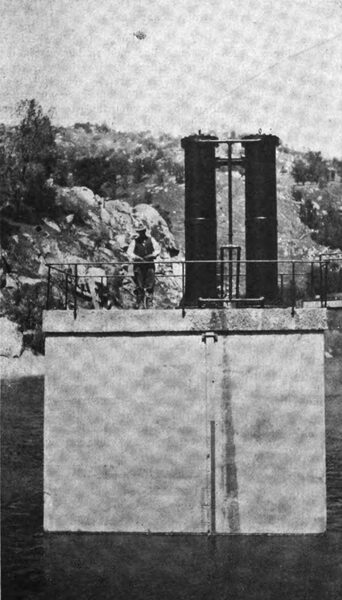
| Intake Dam and Gates |
Fastened with bolts to the cast steel rim of each wheel are eighteen bronze buckets, much like modern buckets in use elsewhere on the Coast. Before the wheels were con- structed the company’s engineers carefully checked their mechanical and hydraulic design. The efficiency guarantee, which is to be substantiated by the company’s tests, requires that the water wheel proper shall develop an efficiency at rated load of 82-1/2 per cent. Dead water leaving the wheels flows down the floor to the wheel race into the main tail race. Live water deflected past the wheel by deflecting the nozzle passes over a pair of heavy metal deflector plates, and is killed before it reaches the main tail race. On both sides the wheel races are lined with steel. To keep splash out of the shaft alley they are fitted with a steel back plate. The wheel cases are made of cast iron, are of graceful form, and fitted with compound baffles to prevent water from cropping out of them along the shaft. Enough space was left between the two exciters to allow the insertion of a large induction motor if it became necessary. The motor would be designed for a good speed regulation and connection, by a pair of clutches to either one of the exciters. The governors are self-contained, oil-actuated, have their pumps immersed in their oil reservoir, and are driven by a silent chain from the generator shafts.
Each main unit is carried on two 16-inchx48-inch babbitted bearings, each bearing fitted with six oil rings for flooding them with oil for cellars contained in their pedestals. The oil is cooled in the pedestals by water coils, built into them. In the lower portions of the bearings are numerous small openings connected to a triplex power-driven pump, capable of supplying oil at a pressure of 1,000 lbs. per square inch.
At both ends the shaft flares, forming a flange to which a wheel disc is bolted. At the center it is enlarged to carry the cast steel pole rim and spider, a single casting weighing 26 tons. To the exterior of this rim are wedged the pole pieces.
The generators have no unusual features. Their stationary armatures are bar wound for 2,300 volts, three-phase. The exciters are two-bearing, with a. water wheel on one end and a fly wheel for close regulation on the other. These units are standard direct-current machines, generating at 125 volts, flat compounded, running at 430 revolutions, and fitted with ordinary self-adjusting bearings. They were furnished by the General Electric Company.
| |||
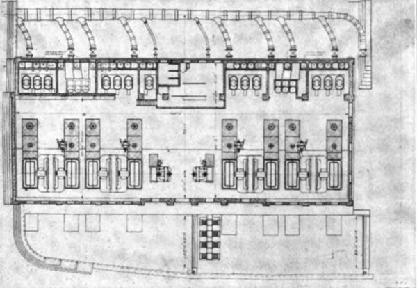
| Plan of Power House |
 |
| Power House Section |
In the station are thirteen transformers, 1667 kilowatts, oil-filled, shell type, oil-circulated, in boiler-iron cases. They are grouped in four banks to receive energy at 2,300 volts delta from the machines, and to supply it to the line at 75,000 volts Y. Taps are provided for intermediate voltages of 56,250 and 37,500. Instead of having internal water cooling coils, the transformers are so constructed that oil sup- plied to them under a slight pressure automatically distributes throughout the windings, and returns by gravity to the waste pipe. The piping and connections for this circulation, consisting of a 4-inch supply line, a 6-inch return line, and a 4-inch waste, are in the basement of the power house. Coming from the transformers, the oil enters a receiving drum, from which it is drawn by two 5-inch centrifugal pumps, motor-driven by variable speed direct-current motors. In an emergency, either pump can supply the station. The oil is forced by these pumps through a set of boiler tube coolers with a total area of 4,500 square feet, re- turning from these to a pressure line which supplies the transformers. Strainers, by-passes, and other auxiliaries are so placed that the entrance of foreign matter into the oil cannot cause trouble throughout all the banks. The system is under pressure from the time the oil enters the pump. Any leakage will, therefore, be outward, and there is no possibility of the leakage of water into the oil, as is the case where water coils under pressure are placed in oil-filled transformers. The installation cost of such a system is less than that of a similar installation using water cooling. Water for the cooling sections is by-passed from one of the exciter tail-races into a flume built across the top of the coolers. The generator leads pass through ducts to the generator switches, thence to the low tension side of the transformer banks. Although the station is not equipped with a complete 2,300-volt bus bar, tie switches are placed between adjacent machines, and equipped with double-throw switches in such a manner that any generator can be transferred if necessary to any single transformer bank, or run in multiple with some other generator on a single transformer bank, or the entire station can be tied together by means of this transfer bus and operated as a single unit.
On the high tension side the transformer banks connect through knife-blade switches with a single bus bar, sectioned in the middle. The two outgoing circuits are tapped of this bus bar between adjacent transformer banks through remote control, non-automatic oil switches. By using these and the oil section switch, all high-tension power switching can be handled without the use of air break switches, and the in- vestment for high grade switching is reduced to a minimum. The 2,300-volt oil switches are installed in concrete cells, having concrete barrier walls and tops. Where possible, the disconnecting switches are separated by barrier walls. In addition to installing the 60,000-volt oil switches in concrete cells, in accordance with standard practice, each has been enclosed in a separate concrete room containing no. additional apparatus except lightning arresters. The high tension wiring is run in ducts, no open wiring being permitted except connections from transformers to the wall through their disconnecting switches, and from the disconnecting switches of the lightning arresters to the lightning arrester banks.
The arresters, of the General Electric Company’s multiplex type, consist of alternate carbon spark gaps and resistance, in accordance with the most modern practice. The circuits are equipped with choke coils, consisting of twenty coils of hard drawn copper placed between the arresters and the oil switches.
| |||
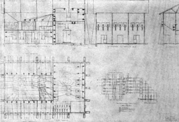
| Substation and Switch-House |
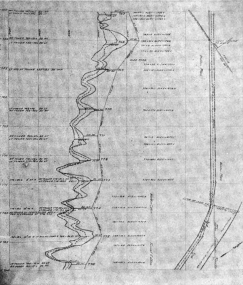
The transmission line follows as near a straight line as possible from the power house to the mouth of the canyon. Swinging to the left there it crosses the Cottonwood Hills, and there takes a course due south across the edge of the Bakersfield plains. Entering the mountainous section through Tejon Canyon and following across the end of Castaic Lake it crosses the divide immediately above Germain Station, where it is at its steepest portion, dropping from the hill to the road below 1,000 feet in 3,500 feet.
Great difficulty was encountered, establishing the next section, which follows the Piru Creek and tributaries. No permanent wagon road could be established, in the last five miles, making heavy angles both vertical and horizontal necessary. One U bend of the river was crossed by means of a long span, 2,250 feet, between the main supports, guided by an entirely unloaded tower at the bottom of the sag.
Leaving the Piru Canyon the line passes in almost a straight line across fifteen miles of rocky land, and after leaving the last crest, it enters the more open district sur- rounding Newhall, through which a permanent wagon road, to haul supplies, and to permit patrolling, was constructed, the maximum grade of which on one side was 10 per cent, and on the other at one place 20 per cent, the ruling grade in both directions being 5 per cent.
| |||
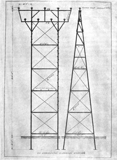
| Steel Transmission Tower |
| |||
| Steel Transmission Tower |
In the Newhall district the line crosses the San Fernando Mountains directly west of the long tunnel on the Southern Pacific, running from there through open country in sight of the railroad most of the way to Los Angeles.
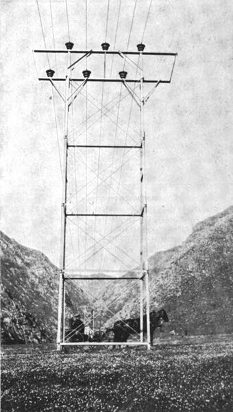
The towers, ranging in height from thirty to sixty feet, are uniformly constructed of galvanized angle iron, bolted with galvanized bolts and held in shape by means of tension rods. With the exception of one pair in the upper portions of the sides and. between the cross-arms, there are no compression braces. The nine insulators are spaced on six-foot centers, five on the upper arm and four on the lower.
 |
| Transmission Line |
The towers, all portions of which are figured to be safe under a wind pressure of thirty pounds per square foot on the tower and the wire of a 700-foot span, will withstand the absolute failure of any single wire, none of the resultant strain being transmitted to adjacent wires nothwithstanding.
No cast-iron was used except in the foot plates, which are twenty-four inches in diameter, painted black. They are attached to the bottom of 4x4-foot galvanized posts, painted black, bolted as extensions to the corner posts of the tower and set in the ground at depth of six feet in tapered holes. No concrete footings were used, except in some places in the city of Los Angeles, where the tower heights in many instances exceed sixty feet. The tower parts were made as light as possible with a factor of safety of each steel member of not less than 2-1/2. All connections are made with malleable iron castings with a factor of safety of 4. The insulator pins are cast steel and furnished as a part of the tower, bolted to the tower with four bolts and cemented into the insulators.
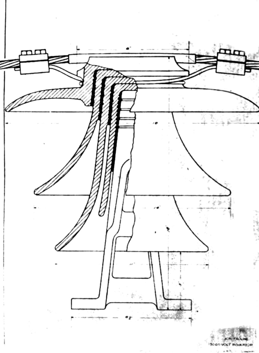 |
| 75,000 Volt Insulator |
The transmission line is designed to consist of three circuits with the wiring spaced symmetrically on six-foot centers. The wire, sampled and tested at the mill before accepted, is 7-strand 4/o hard drawn copper, having elastic limit exceeding 35,000 and an ultimate strength of 62,400 lbs.
The wire was greased and shipped in reels of two lengths of 4000 feet each. As only six conductors are being strung at present it was desirable to leave the easiest circuits to be pulled in later. Three wires were threaded through the cable at a time, by carrying them across rollers bolted to the arm.
The accompanying illustration shows the type of clamp used. The tie wires are of No. 1 copper strand, the four bolt clamps are of brass, and the U piece placed on the top of the insulator to prevent chafing is made of No. 24 copper.
The tie wires fail in test at about 4000 pounds, while the insulators are guaranteed to stand 4000 pounds and fail at approximately 9000 pounds, thus making the normal failing point uniform.
The transmission line was carried on as long spans as the character of the country would permit, with towers not exceeding sixty feet in height. The clearance on telephone wires was made at a minimum of seven feet while the ground clearance was determined by the survey party as it went along.
The transmission lines are carried through from one end to the other with transpositions only at switching stations, of which at present there are but three, two of which contain transformer sub-stations.
The switching station proper is equipped with two sets of oil break switches, connected one set after another into a complete circle for each line, and two sets of knife-blade disconnecting switches for each line. After passing through the disconnecting switches the incoming lines are tapped between alternate oil switches. The corresponding outgoing circuits, from the vacant pumpers left after the lines have been tapped in, leave the building on the opposite side.
These buildings are made from concrete. The circuits are isolated from each other by means of concrete barriers and floors. Individual leads of the same circuit are run in the same compartment. Horn lightning arresters can be connected to the circuits at these sub-stations at any time if necessary.
The switching station at which are located the two trans- former sub-stations are arranged the same as the others, except that openings were made in the west wall, through which to take leads into the adjacent transformer house. Provision has been made in the transformer house for two banks of 2100 kilowatt transformers from the transmission line at 60,000 volts and delivering to the distribution at 30,000. The high tension leads are tapped from two of the outgoing 60,000-volt circuits in the switching house, pass through oil switches and join in a common bus, from which the transformers can be separated by means of knife-blade switches.
The switchboard for all switching except the trans- former switching is on a concrete deck, on the underside of which are hung the insulators for the 30,000-volt circuits, while the 30,000-volt oil switches are placed on top of the floor. The lightning arresters for the 60,000-volt circuits are on the wall between the transformer and the switch house, separated from each other by 6-foot barriers, while at the end of the sub-station below the oil switches and the outgoing 30,000-volt circuits are placed the 30,000-volt lightning arresters.
One bank of 2100 kilowatt, oil-filled, water-cooled transformers will be installed at present at Castaic to supply a 30,000-volt transmission now being built by the Ventura County Power Company west from Castaic to Saticoy where a branch is taken to Oxnard and will be eventually continued to Santa Barbara, where the Edison Electric Company has extensive holdings.
Another 1200-kilowatt bank of the same type transformers will be installed at present at Fernando to supply local light and power at 2300 volts.
The terminal of the transmission line in Los Angeles is at the steam and transformer station known as Los Angeles No. 3. The two circuits enter the station through the east gable, pass through choke coils and enter oil switches which connect them to their respective bus bars. There is an oil switch between the two busses. Each transformer has an oil switch which can be connected by means of a double-throw, knife-blade switch to the bus bar belonging to the west or the middle circuit. The east circuit will be brought in so it can be switched on either of the bus bars. There are four step-down transformer banks, 4500 kilowatt, with their secondaries wound for either 16,000 or 32,000 volts. Under ordinary conditions the energy received from the Kern River will be handled through the double 15,000-volt
bus. The transformers are oil circulated, the oil being cooled in the same manner as that at the Kern River Plant No. 1, with the exception that the cooling water is circulated continuously from the oil-cooler basin into elevated troughs, from which it drops through a series of screens.
This building also contains provision for switching the old 30,000-volt transmission line with its various branches and all the 15,000-volt distribution around Los Angeles.
All bus bar wiring connections to the transformers and the outgoing circuits are carried in ducts. In the new portion of the station these are pulled with 15,000-volt leaded paper cables of 211,000 centimeter cross section, with the exception of the Westinghouse generator, which has 400,000 centimeter cables.
In 1903 two 2000-kilowatt, 2300-volt Curtis turbine alternators, with 4000 horsepower of Sterling boilers were established in units of 500 horsepower each, but in 1905 larger sized apparatus was determined upon throughout, and 5250 horsepower of 750 horsepower units was established in the boiler room. The new boilers have heavy drums fitted with superheaters in the middle drum instead of Niclasse super-heaters as used in the old boilers, and are fitted to carry 175 pounds pressure, although the plant is now operated with 165 pounds at the boiler. The boilers are constructed to produce 150 degrees at the ‘throttle against 125 degrees of the old plant. Cold water entering in the back drums passes down through the back tubes, up through the front ones, across into one end of the superheater drum, through the superheater tubes to the other end and out through the superheated steam line.
The turbine installation in the new plant consists of a single 6000-kilowatt Westinghouse-Parsons turbo alternator, with Worthington condensing equipment. The steam end is of their standard construction, receiving steam through an intermittent valve, which steam, before reaching the machine, passes through a separator, an automatic butterfly valve and. a hand-operated throttle valve. This unit is four-stage, single flow, and is operated from 27-1/2-inch to 28-inch vacuum. The by-pass throttle does not open until 9000- kilowatt load is. reached under normal steam and vacuum conditions, and so far loads up to 9000 kilowatts have been carried on the machine without any indications of the maximum load being approached. This generator is wound for 16,500 volts Y and is run with grounded neutral on the 50-cycle distribution of the company. It runs in multiple with the main system perfectly. Between the neutral of the machine and the station ground wire, a potential difference of several hundred volts exists under operating conditions, which place the machine in connection with Y to delta connected transformer banks. This voltage and the resultant flow where the neutral switches close varies with the number of transformers and the load on them, but does not appear to vary from other causes.
The plant is equipped with steam condensers, heaters, vacuum pumps, coolers, etc.
This unit was put in service in October, 1906, and has been run ever since without any shut-down due to the turbine and without any shut-down of any seriousness

