[Trade Journal]
Publication: Scientific American Supplement
New York, NY, United States
vol. 44, no. 1649, p. 85-86, col. 1-3
THREE NEW ELECTRICAL DEVICES
IMPROVEMENTS IN INSULATORS.
THREE Inventions, two of them new Insulating devices, and the third a horizontal support for conductors, have recently been patented by Mr. Louis Steinberger, Brooklyn, N. Y. The first, a simple and ingenious insulating pin for supporting conductors carrying heavy currents, is shown in the accompanying engravings. Figs. 1 and 2 show front elevation and plan view of a cross-arm fitted with the pin; Fig. 3 is a vertical central section along the line 3, 3 in Fig. 2, and Fig. 4 a similar section along the line 4, 4. Fig. 5 shows a section through the pin at 5, 5, Fig. 4. A central solid rod, 11, preferably of fiber, dry wood, or other insulating material, is surrounded by a plurality of tubes, 11a, 11b, also of some insulating material, such as fiber or mica, chosen tor having considerable mechanical strength. This composite core is imbedded in, and concentric with, the pin body, its purpose being to confer mechanical strength and to increase the insulating qualities of the body. The pin body 6, terminating at its upper end in a thread 7, is made of some suitable insulating material, preferably electrose. A weather shield, 8, is integral with the body. This weather shield is furnished with a trough, 9, and depressed lips, 10, which shed moisture away from the supporting cross-arm. The shield is further provided with drip surfaces, 12a, raised from the cross-arm by a space, 12, as shown in Fig. 3. This space is annular and forms a dry space round the junction of the pin with the support.
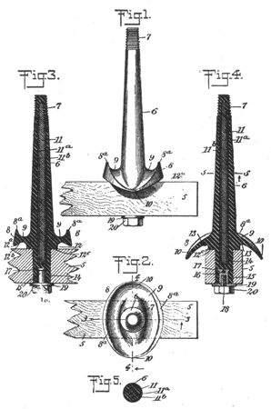 |
The pin body is provided with an annular shoulder, 12c, and with a stem, 14. Imbedded in this stem is a metallic sleeve. This sleeve is placed in position when the stem is plastic, and it is provided with a slot and a flange to hold it more firmly in place. This sleeve is completely separated from the composite core. To place in position the pin is placed in the cross-arm as shown in Figs. 3 and 4, when the shoulder, 12c, fits down on the upper surface of the arm, forming a watertight joint which is further protected by the dry space, 12 The sleeve, 15, is threaded inwardly and a screw, 18, with head, 20, is fitted into it and holds the pin firmly in position.
 |
| Fig. 6. |
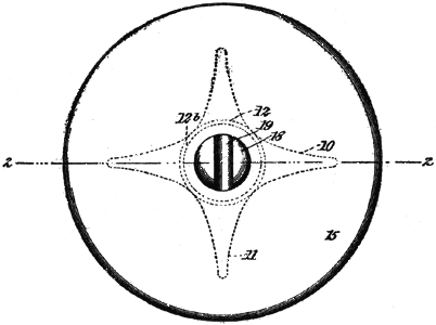
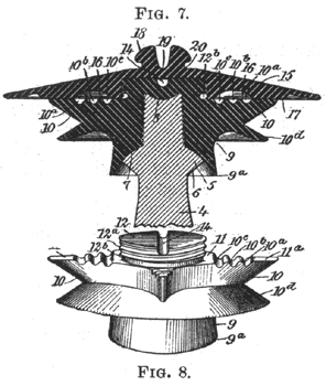
The second insulator device, intended particularly for heavy currents and to prevent arcing from the line to the support, and which provides a number of supporting portions for the conductor as well as means for supporting a number of conductors on the same insulator, is illustrated in Figs. 6, 7, and 8. Fig. 6 is a plan view of the Insulator; Fig. 7 is a vertical section through Fig. 6 along the line 2, 2; and Fig. 8 is a perspective view of the lower Insulator body without the supporting pin or the upper hood. The supporting pin is shown at 4. Fig. 7, with a vertical boss, 8, threaded externally, rising from a spheroidal upper surface, 7. The insulator body, which may be of electrose, is provided with a skirt, 9a, shaped to fit the spheroidal surface of t.he supporting pin. The insulator body is also provided with a number of radial supporting ribs, 10, each terminating at Its upper edge in a flat surface, 11a; and with an annular skirt 10d. The upper part of the insulator body is in the form of a threaded boss, 12, with a slot, 14, extending across its top. A groove, 12b, encircles the boss and may be used for retaining a tie wire. A hood, 15, Fig. 7, is provided on its under surface with an annular channel, 16, bounded by a bead, 17. When the hood is in place this bead fits snugly down on the flat surface, 11a; and the channel, 16, arches over the notches 10a, 10b, 10c, in the ribs 11. The hood is shaped into a boss at 18, having a slot, 19, in which the cable or conductor normally rests, being held in position by a tie wire in the groove, 12b. If the boss be broken the conductor may rest within the slot, 14, and be kept in position with a tie wire in the groove, 12b. The notches, 10a, 10b, 10c, increase the surface over which leakage may take place and so tend to diminish surface leakage; they are also available if required as supports for additional conductors. The supporting ribs, 10, receive a part of the weight of the hood upon their upper surfaces 11, lid, and are constructed to distribute its weight as equally as possible with regard to the insulator body, 9. The spheroidal upper surface 7, of the supporting pin, and lower surface, 9a, of the insulating material are modeled to fit neatly wherever they engage. By smooth fitting and a careful adjustment for strain a high measure of strength is obtained with a minimum of constructive weight.
 |
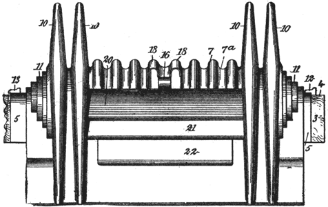
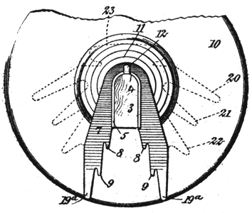
The horizontal support for cables, wires or similar conductors, one possessing novel and ingenious features, is shown in the accompanying diagram. Fig. 9 is a front elevation of the insulator, all movable parts being removed; and Fig. 10 is a fragmentary side elevation. Fig. 11 is a vertical longitudinal section through the insulator and its support, along the line 3,3 of Fig. 12; and Fig. 12 is a central cross section upon the line 4, 4 of Fig. 11, showing the way in which the cable is mounted and its tension controlled. Fig. 10 shows the cross arm, 3, the upper edge of which is rounded and fitted with a metal saddle, 5. Molded rigidly on this saddle is a body portion 7, of insulating material made comparatively thick and provided internally with petticoats 8, 9. The ends of the body portion are provided with steps 11, for the purpose of shedding moisture away from the cross-arm. A number of disks, 10, are spaced apart, there being two of them to each end of the body portion and integral with it. The middle surface of the body portion, 7, is provided with corrugations, 7a, these diverting moisture to flow at right angles to the general plane occupied by the cross-arm, and at the same time diminishing the chances of surface leakage.
 |
| Fig. 9. |
The saddle, 5, on which the body portion is molded, is held in position by metallic spikes, 12, 13, driven into the cross-arm; these may be driven through the saddle, insuring that no displacement can take place. The lower edges, 19a, of the body of insulating material are flush with the lower edges of the disks, 10; the body is also provided with horizontally-disposed sheds, 20, 21, 22, spaced apart for the double purpose of facilitating the drainage of moisture and decreasing surface leakage; and its upper surface is molded into a support, 23, Fig. 12, to hold the wearing plate.
 |
| Fig. 10. |
A wearing plate, 14, shown in detail in Fig. 13, is imbedded within the body of insulating material as shown in position in Figs. 11 and 12. A link, 24, attached by a pin to the wearing plate, is provided with a threaded bolt, 25, and connected with this bolt is a revoluble buckle, 26, connected in its turn by a second bolt and pivot to a clamp, 28. There are two of these clamps, one attached to each end of the wearing plate, but only one connected by a revoluble buckle. They are shown in perspective, with their attachments in Fig. 12; they are made in halves and the detail of construction is given in Fig. 14. Each of the clamps is firmly gripped upon a cable, 35, and held in position thereto and to each other by the bolts, 36. The clamp to the left in Fig. 12 is connected with the buckle, 26, by the pivoted bolt, 38. The bolts, 25 and 38, are threaded oppositely so that the rotation of the buckle tends to tighten or slacken the cable.
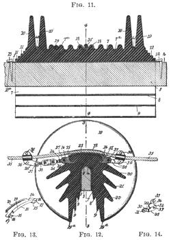 |
In use the cable, 35, rests centrally along the wearing plate, 14, being held in place partially by its own weight. The clamps and turnbuckle are next placed in position and the clamps bolted to the cable. This obviates any chafing of the insulating material, for all wear is borne by the plate. If it is desired to adjust the cable this may be done by turning the turn-buckle, 26, so as to pull the cable in the direction required. By the use of this turnbuckle, with the clamps tightly gripping the cable, the small portion of the cable between the clamps may be made to buckle slightly, thus transferring most of the strain from the top of the wearing plate to its ends. If the cable should break the slack cannot extend farther than the two insulators located on the opposite sides of the break.
The corrugations, 7a, not only serve to retard the creep of moisture by breaking up the surface of the insulator, but also serve if required as rests for additional cables. If for any reason the cable, 35, should become detached from its fastening it may still rest between these corrugations.
It will be noted that the disks, 10, taper. Wires may therefore be inserted between them, as 40 and 41, Fig. 11, and wedged firmly in position. Thus a telegraph or telephone wire, or even a so-called "third" wire, may be carried without detriment to the general usefulness of the insulator.
