[Trade Journal]
Publication: Electric Journal
Pittsburgh, PA, United States
vol. 4, p. 568-577
THE DESIGN AND TESTING OF ELECTRICAL PORCELAIN
DEAN HARVEY
ALTHOUGH high grade porcelain ware, or china, has been manufactured for many centuries, it is only a few years since the use of this material has been extended to the electrical industries. The design of electrical porcelain differs materially from that of ordinary ware on account of the different characteristics desired. High dielectric and great mechanical strength are required, especially in certain types of construction, such as overhead lines, etc. It has been necessary, therefore, to devise new processes to facilitate the manufacture of the new shapes. The methods of manufacture and principles of design are now practically standardized for a large proportion of this material. Careful designing is required to obtain the best results not only to secure porcelain best adopted to the service, but also so that it may be manufactured readily and economically. Quite often a slight change in design will not interfere at all with the design of the apparatus with which the porcelain is to be used, and will render the porcelain much less difficult to manufacture and therefore less expensive.
The price of porcelain necessarily includes both the actual cost of manufacture of the pieces used, and in addition the cost of such pieces as are made up and rejected either on account of mechanical imperfections or failure to withstand electrical tests. The materials used in the manufacture of porcelain are relatively inexpensive as compared with the cost of manufacture, and are not considered in estimating costs. A large insulator is more expensive than a small one, not on account of the larger amount of material used, but because of the greater difficulty in the manufacture. The cost of porcelain is largely dependent upon the number of pieces which can be placed in the kiln at one time, as the cost of firing is practically the same, regardless of the amount of porcelain in the kiln. A metal die is required when "dry pressed" ware is to be made and its cost must also be considered.
GLAZES
When glazed porcelain ware is fired, the pieces must be separated so that they will not be held together by the glaze. Unglazed porcelain is less expensive to manufacture than the glazed material because the extra operation of dipping in the glazing fluid and drying again before firing is avoided, and in addition the pieces may be placed directly in contact with each other, or, if of small size, piled up indiscriminately, thus allowing a much larger number to be fired at the same time. The surface of the porcelain at points of support during firing must be left unglazed so that the ware will not adhere to the seggar, unless it is supported on small pieces of bittstone. This material, however, is not generally used, as it has to be ground off after the firing to produce a smooth surface. Small porcelain bases and similar pieces can usually be fired best when supported on one edge. Standing the ware on edge is also advantageous because more pieces may be placed in the same seggar.
 |
| Bay Counties 1900 50,000 Volt Insulator |
 |
| Shawinigan 1902 50,000 Volt Insulator |
If placed flat they are likely to conform to the surface of the seggar and become warped if that surface does not remain perfectly flat. While the seggars will withstand a higher temperature than porcelain ware, both of these materials soften somewhat at the high temperatures obtained in kilns during firing and tend to conform to the shape of the supporting surfaces.
The use of a glaze on porcelain insulators is usually desirable, as it provides a smooth, glossy surface which does not accumulate dirt and moisture as readily as the rougher unglazed surface. The glaze also provides a convenient means of coloring insulators so as to correspond more nearly to the color of the apparatus with which it is used. The brown glaze has become practically standard for porcelain insulators used on outdoor overhead lines, because it is less conspicuous than white porcelain, and hence less liable to be used as marks and broken by rifle shots. Experience has shown that on two parallel lines equipped with white and brown-glazed insulators, respectively, the breakage was much greater on the line having the white insulators.
PROCESSES
The "dry process" of porcelain manufacture is suitable only for the manufacture of such porcelain pieces as can be formed by means of metal dies, and which are to be used on comparatively low voltages. The clay, which is rather dry when pressed in the die, does not have the compact body obtained by the "wet process," and necessary for high potential porcelain. Dry process porcelain, unless manufactured with the greatest care, is somewhat porous, and hence is liable to absorb moisture. This process is, however, suitable for the manufacture of low voltage porcelain, such as bases for fuse blocks, etc., and especially for pieces of irregular shapes, which cannot be turned.
 |
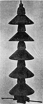
| Guanajuato - 1905 60,000 Volt Insulator |
 |
| Rio Janeiro 1907 88,000 Volt Insulator |
The methods of manufacture of wet process porcelain have been fully described in a former article.* This porcelain is of the quality particularly adapted to high voltages, and may be made in any form that can be turned in a lathe or formed on a potter's wheel by means of a profile tool and plaster mould. The sections of multiple part line insulators are made by this latter process. Wet process porcelain costs more to manufacture than the dry pressed ware, when made in quantities, because it is made by hand, but is less expensive than the latter material when only a few pieces arc needed, as it does not require a die.
DIMENSIONS
Porcelain should be as nearly in. i form in thickness as possible, as this facilitates uniform drying f the material. Pieces having considerable variation in thickness are very likely to become cracked or warped during the process of drying and firing. It is customary to allow certain variations in the dimensions of porcelain insulators from those specified. A reasonable variation is one and one-half percent either way for dry pressed ware (or three percent total), and three percent either way for wet process porcelain (or six percent total), this larger variation being allowed because the ware is made by hand. Greater accuracy may be obtained, but in that case the cost will be higher on account of the larger proportion of pieces rejected.
 |
| Porcelain Wall Outlets for Medium and High Voltages |
LIMITING VOLTAGES
Porcelain of the best quality is of very high dielectric strength. As the thickness is increased, however, it becomes much more difficult to obtain well vitrified ware without small cracks or other flaws in the interior. This fact practically limits the voltage which a single piece of porcelain can withstand, and it is therefore customary to use multiple-part insulators for the higher voltages. In general, insulators should be designed so that no single piece will be tested at more than 80000 volts, and a somewhat lower test is desirable.
| |||
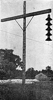
| New Insulator for Extra High Voltage Service |
| |||
| Method of Supporting Insulator for Extra High Voltage (1) |
There is a common impression that breakdown over a high tension insulator is due to surface leakage. Unless the surfaces are wet or are covered with some conducting material, there is no appreciable leakage of current, as the only current flowing is the charging current of the insulator considered as a condenser, which is of small amount. The principal cause of the breakdown seems to be the rupture of the film of air immediately adjacent to the insulator, on account of excessive electro-static strain. The dielectric between a circuit and ground consists not only of the porcelain insulator, but also of the air adjacent to it. When a dielectric is composed of several materials in series, that material having the lowest dielectric strength will be the first to break down, other things being equal. It is a well known fact that air has a much lower dielectric strength than either glass or porcelain. When a gradually increasing voltage is applied to a porcelain line insulator with a metal pin, the only current that passes at first is the very small charging current of the insulator. When a certain voltage is reached, the electro-static field attains such a strength that the air near the two attains such a strength that the air near the two terminals or electrodes is ruptured, causing a brush discharge, and the ruptured air becomes a semi-conductor serving to extend the electrodes, and therefore increase the current. This rupturing of the film of air and consequent increase in the electrodes and in the brush discharge, tends to continue indefinitely, but is retarded by the cooling effect of the porcelain, its shape, etc. A slight increase in the voltage, however, will considerably extend the area of the brush discharge. The thickness of the dielectric at the top of many line insulators is small, causing a strong electro-static field at that point, which tends to rupture the air. The shape of the insulator has much to do with this action, as, by proper design, the surface of the porcelain may be brought out into an electro-static field so weak that the air adjacent to the porcelain cannot break down under its influence. (2)
LINE INSULATORS
Insulators for outdoor service, in addition to meeting the requirements for interior work, should be so designed that they will withstand the most extreme weather conditions of the locality in which they are to be used. Climatic conditions vary so much in different sections of the country that an insulator which proved entirely satisfactory in one locality might be inadequate for similar service in another territory. For instance, the conditions near the sea coast with its salt fog are much more severe than in dry mountainous regions. Insulators are also subjected to very severe conditions in certain localities on account of excessive condensation of moisture due to sudden and extreme changes in temperature. A striking illustration of the effect of sudden variation in temperature on insulators has occurred on several lines, where parts of glass insulators have cracked off owing to the sudden warmth on one side of the insulators at sunrise. On account of these variations in service conditions, definite information regarding the size of line insulators required for a certain voltage cannot be given; but the necessary dimensions of the insulator can best be obtained by a study of the various forms which have operated successfully under similar conditions.
With the increase in voltage of high-tension transmission lines has come the demand for larger and stronger insulators. Insulators of large size are made in several parts, held together either by cement or glazed together while being fired. Neat Portland cement or litharge and glycerine are commonly used for cementing the parts together. For the higher voltages, steel towers have been used instead of wooden poles, with long spans between towers, thus reducing the number of insulators necessary, but requiring both insulators and pins of great mechanical strength. The limiting size for this style of insulator and pin has practically been reached, and for voltages higher than 90000 volts, a new form of support for line wires is needed. Experimental work has been carried on with several types of suspended insulators, in which insulating discs of various shapes have been strung together in series to support the line. One high potential line is now being equipped with this type of insulator, but the new construction is still in the development stage, and experience only can determine whether or not it is best adapted for the service conditions.
PORCELAIN VS GLASS INSULATORS
Glass insulators have been used to quite an extent on circuits of less than 25,000 volts. They have the advantage of low cost and cheap inspection. Defects in the material which would interfere with its dielectric strength may be found by inspection, thus rendering electrical tests unnecessary. Glass, however, is open to the serious objection that material which has not been properly annealed is likely to have stresses set up within it which will cause it to break when exposed to comparatively slight changes of temperature. Porcelain is somewhat more expensive than glass, but has greater mechanical strength and is less brittle. Very careful tests for dielectric strength are required in order to determine the quality of porcelain insulators, as defective material ordinarily cannot be detected by examination.
WOODEN VS METAL PINS FOR LINE INSULATORS
Electrical engineers have been divided in opinion as to the relative merits of wooden and metal pins for porcelain line insulators. The wooden pin has an advantage in that it provides a certain amount of insulation, and the electro-static field with the resultant brush discharge is much less pronounced than with a metal pin. But the wooden pin is subject to injury by brush discharge at the pin, and when this occurs or an insulator breaks down the pin is usually destroyed, thus allowing the line to fall and frequently burning a cross-arm. The metal pin has the advantage of greater mechanical strength and holds the insulator and line in position even though the insulator may have broken down electrically. The metal pin is considered preferable for use with insulators which have ample margin of safety for the service conditions. When this margin of safety cannot be obtained by the insulator alone, a wooden pin is advisable in order to obtain the necessary insulation. However, with long spans, especially at -high voltages, metal pins are necessary in order to obtain the required mechanical strength.
ELECTRICAL TESTS
In general, the conditions under which tests are made should correspond as nearly as possible to the conditions of service. It is customary to test porcelain parts at a somewhat higher voltage than they will be subjected to during the tests upon the finished apparatus in which they are used, in order to allow for slight variations in the voltage of the testing circuit and prevent the breakdown of the porcelain after assembly. Practice has clearly established the fact that a time test is necessary in order to detect defects, as insulators which withstand a certain test voltage momentarily will not necessarily withstand it continuously, or even for a short time. The usual time for a high voltage test is one minute.
| |||
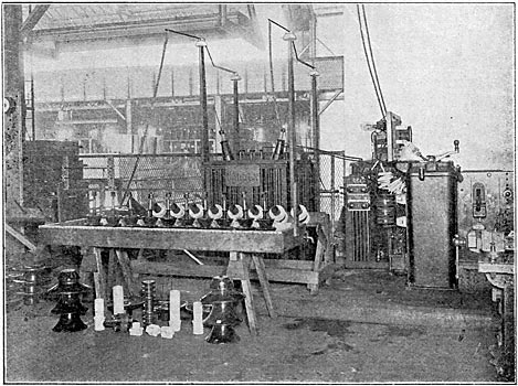
| Fig. I General View Op An Insulator Testing Department Showing Transformer, Controlling Apparatus, Insulators in Water Trough and Bushings Fitted With Jigs on Testing Rack, Also Some of the Types of Insulators Tested. |
In order to detect the point at which the breakdown of an insulator occurs, it is sometimes desirable to apply the testing voltage for a sufficient length of time to burn a larger hole at the point of puncture. One of the most convenient methods for accomplishing this result is to place a resistance or reactance in parallel with the circuit breaker in the primary circuit of the testing transformer. When the overload caused by the breakdown of the insulator opens the circuit breaker the reactance is automatically thrown in series with the transformer and cuts down the current. The reactance may be proportioned so as to allow only full-load current in the transformer so that the burning of the insulator may be continued without injury to the transformer.
 |
| Fig. 2 Diagram of Connections for Testing Arrangement Shown in Fig. 1. |
Fig. 1 shows a testing outfit for testing porcelain insulators, and Fig. 2 gives the diagram of connections. Variations in voltage are obtained by varying the primary voltage of the testing transformer by means of a regulating transformer, auto-transformer and oil drum regulator. Two regulator drums are used in order to provide for small variations in the test voltage. The two pilot lamps indicate the direction in which to turn the auxiliary drum. In order to raise the voltage by five percent steps, the main drum is operated. To raise the voltage by one- fourth percent steps the auxiliary drum is moved clockwise if the right hand pilot lamp is moved clockwise if the right hand pilot lamp is lighted, or counter-clockwise if the left hand pilot lamp is lighted. When the auxiliary drum is moved until against the stop, the main drum is to be moved one notch and then the auxiliary drum moved in the opposite direction. A choke coil is connected in parallel with the oil circuit breaker to allow punctures in insulators to be located as described above. A number of series transformers with different ratios are used in connection with a tripping coil to give the circuit breaker a wide range. Testing racks, a variety of suitable jigs, and other fittings facilitate the quick handling and testing of a number of insulators at the same time.
| |||
| Fig. 3 Testing Department of A Large Porcelain Manufacturing Establishment |
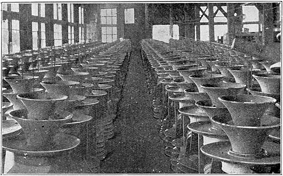
One of the most convenient methods of testing porcelain line insulators and similar material is to place the insulators in a water trough so that the water forms one terminal of the insulator. Porcelain line insulators arc tested in this manner, the insulators being inverted, with the head immersed in water so as to cover the side wire groove, and with the hole for the pin filled with water to serve as the other terminal. The testing department of a large porcelain factory is shown in Fig. 3. The porcelain pieces under test are large multiple-part line insulators. Each part is tested separately before assembly, and the complete insulators are also tested.
(1) Other types of suspended insulators are described in papers before the American Institute of Electrical Engineers, June. 1907, by E. M. Hewlett and H. W. Buck.
(2) For more extended information on this subject see "The Construction and installation of High Potential Lines," by Mr. M. H. Gerry, P. 364-388, Trans. International Electrical Congress, St. Louis, 1904.
