[Trade Journal]
Publication: Electrical World
New York, NY, United States
vol. 50, no. 15, p. 713-717, col. 1-2
Hydro-Electric Power and Transmission Plant at West Buxton, Maine.
The supply of electricity for municipal and private use in Portland, Maine, has recently been largely increased and improved by the operation of the new station of the Portland Electric Company. This is a hydro-electric development on the Saco River at West Buxton, about 20 miles from the city, and will amount to 4000 horse-power, produced by four units, of which three are now installed. The electrical energy is transmitted at a potential of 22,000 volts, to the main transformer station in the suburbs of Portland. The development has been carried out by J. G. White & Company, and several interesting features have been introduced in both the design and construction.
While of moderate size the plant at West Buxton represents the best and latest practice in water-power development and utilizes the energy of the river at the point of location practically to its full extent. The accompanying illustrations convey an excellent idea of principal points of the design. In the construction the most notable feature, considering climatic conditions and the handicap of exceptionally rigorous winter weather, has been the rapid rate of work. Construction was begun on Aug. 3, 1906, and the plant was complete and ready for operation Aug. 12, 1907.
| |||
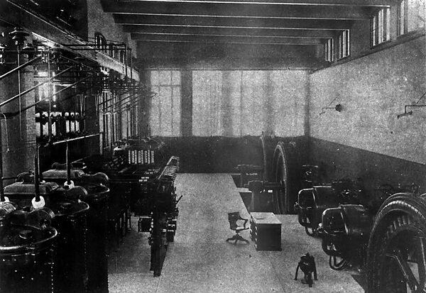
| Fig.1 -- Interior View of the West Buxton Power House Op the Portland Electric Company. |
A review of the electric light and power situation at Portland is interesting in connection with the new installation. The development of the city in recent years has been steady and substantial, and the population has grown at the rate of about 40 per cent per decade. Portland is now one of the most important manufacturing centers of New England, having about 250 well established manufactories. The total capitalization of these is $7,000,000, and nearly 5000 operatives are employed. Portland is, besides, the winter terminal of the Grand Trunk Railroad, electricity being materially augmented by this fact. The large demand for power, coupled with the high cost of coal, has stimulated water-power development and made necessary the installation at West Buxton.
At the present lime there are two principal companies doing the electric lighting and power business of Portland, namely, the Portland Lighting & Power Company, and the Consolidated Electric Light Company of Maine. The Portland Lighting & Power Company is supplied with electricity generated by a hydro-electric plant of 2500 hp, located at Great Falls on the Presumpscot River, 20 miles from Portland. This company has the city lighting contract and also furnishes electricity for commercial purposes, particularly in the suburban territory. The Consolidated Electric Light Company operates a modern and efficient steam plant of about 2800 horse-power in Portland, and supplies most of the general commercial demand of the city, where its distribution system is extensive. A considerable portion of the distribution system is underground. Both of these companies have been running their plants at full capacity for some time.
The West Buxton development, with the transmission lines and the sub-station in Portland, is owned by the Portland Electric Company, and the Consolidated Electric Light Company has contracted for the entire output. It will thereby be enabled to take care of the great influx of new lighting and power contracts signed and in prospect. By the combined operation of the three plants described, Portland is placed in a unique position. Its residents now pay lower rates for electricity than is charged in any other city in New England.
The design of the West Buxton plant, and in particular the transmission system, is based on the purpose of ultimately uniting the service with that of the Great Falls water-power plant at a main transformer station in Portland. The transmission lines from the Great Falls plant are to be carried direct to the new station. This will permit the abandonment of several sub-stations and auxiliary plants. The high-tension current from both West Buxton and Great Falls will be reduced to a uniform pressure of 2300 volts for transmission to the Consolidated Electric Light Companys plant. There, motor generator sets are placed for converting the united output to direct current at 250 volts, which is distributed by a three-wire system throughout the business section of the city. At present there are installed at the main transformer station mentioned, six 500-kw, 22,000/2300-volt self-cooled units, with provision for further transformer equipment to handle the Great Falls output.
| |||
| Fig. 2 -- Power House, One End of Dam and Cofferdam at Point of Final Closure. |
| |||
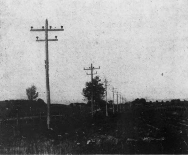
| Fig. 3 -- Main Transmission Line From West Buxton to Portland |
| |||
| Fig. 4 -- Concrete Foundations of Power House in Course of Erection During Winter. |
| |||
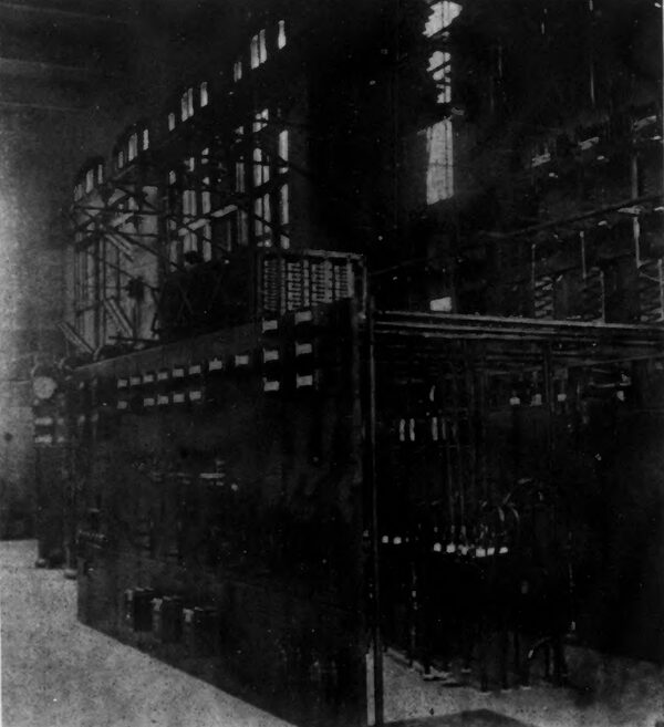
| Fig. 5 -- Switchboard in West Buxton Station. |
The transmission line from the West Buxton plant to Portland consists of two three-phase circuits of No. 2 wire, a metallic telephone circuit of No. 12 copper wire, and a ground circuit of No. 12 phono-electric wire. The main line insulators are triple petticoated, glazed porcelain, and are mounted on hard maple pins. The circuits are carried one on either side of the pole on two cross-arms and the triangles are inverted. The wires are placed 36 ins. apart. The telephone wires are carried on brackets below the lower arm, while the ground wire is run over the tops of the poles and grounded at every sixth pole through a No. 4 B. & S. copper wire, connected by a brass screw-plug with a galvanized-iron pipe driven 6 ft. in the ground. The cross-arms are of long leaf yellow pine, and are doubled at points of curvature on the line. The poles are butt-cut chestnut and vary from 35 ft. to 60 ft. in length, having a minimum diameter at the top of 8 ins. The spacing is l00 ft. on tangents.
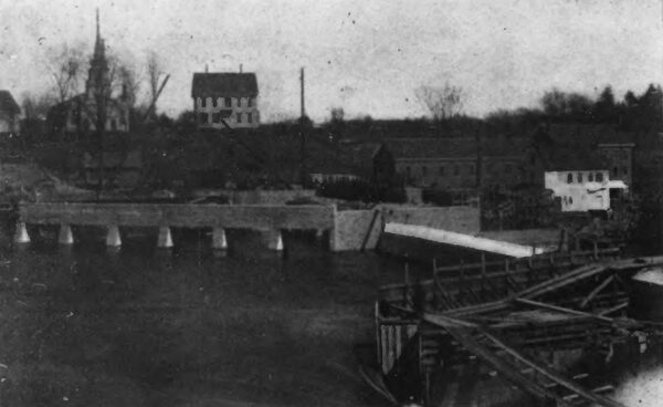
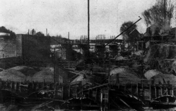
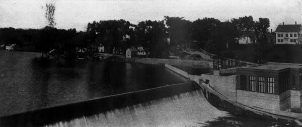
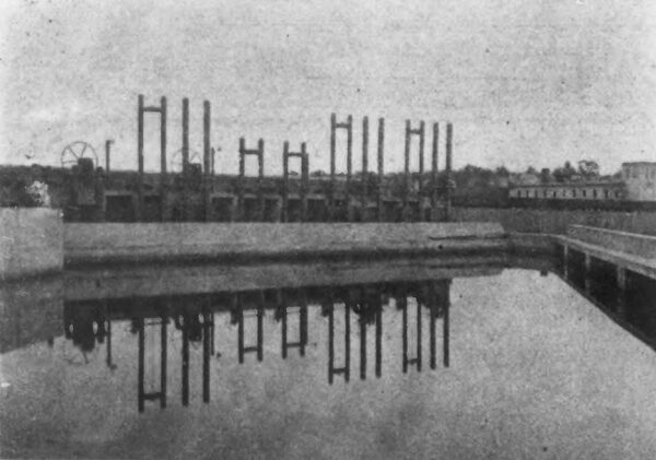
At West Buxton the principal structures of the plant proper are a concrete dam and a power house, which is built of concrete and brick. The power house is located on the east bank of the river, with the dam abutting against it and the water is taken directly from the storage pond. The dam is 300 ft. long, 30 ft. high and 29 ft. thick at the base. It consists essentially of monolithic sections 40 ft. long, keyed together and also into the rock foundation. The entire plant is founded on bed rock. The intake and head works are protected by a reinforced concrete wing wall and boom 140 ft. long running from the abutment of the dam at an angle of 45 deg. to the shore. The lower edge of the boom is sufficiently beneath the surface of the water at all stages of the river so that floating debris will be skimmed off and carried along its face to a chute in the adjacent end of the dam. Six concrete piers support the boom.
| |||
| Fig. 6 -- Dam and Power House of the Portland Electric Company on the Saco River at West Buxton. Maine. |
| |||
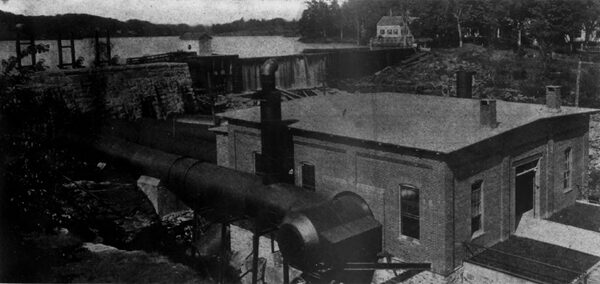
| Fig. 7 -- Great Falls Plant of the Portland Lighting & Power Company on the Presumpscot River. |
The construction, including the placement of the major part of the concrete in both dam and power house, was carried on without interruption throughout last winter, which was exceptionally cold. The cement was mixed with hot water and the rock and sand were thoroughly heated before mixing. Special appliances were devised to carry out the heating process rapidly and economically. Though much of the concrete was placed in a surrounding temperature of 30 deg. below zero, and nearly all of it under freezing conditions, none was injured by freezing and the finished work has proved exceptionally free from defects. The work was safeguarded probably by the expedition with which the mixed material was placed after heating and by the heat stored in the solid constituents which was sufficient to allow the mass to set before it was reduced to a freezing temperature. The control of the river during construction involved some special problems. Use was made in part of an old timber mill dam conveniently located just above the new dam site. The old dam was raised for a part of its length and an area including the situation of the new power house and about 200 ft. of the new dam was surrounded by a cofferdam built downstream from the old dam and then into the east bank of the river. During the construction of these coffers the west abutment and the end section of the dam were being built. When the cofferdam was completed the original timber dam was opened wet of the point where it was joined to the cofferdam and the entire flow of the river was sent through that channel. Then the power-house foundations and the adjacent 200-ft. section of the dam were built in the . . . [illegible text] . . . reclaimed from the river.
The next step was to block the channel, cut through the old dam, thereby directing the flow of the river through the power house and exposing the foundations for the final dam section. The aperture in the old dam was first narrowed as much as possible by constructing cofferdams from each side toward the center. The projecting ends were finished square and parallel, and were provided with shoulders running from top to bottom. Across the narrow remaining opening, heavy joists were laid and upon these joists a massive timber gate was built in position to be dropped into the opening. The supporting joists were then sawed through to the safe limit and dynamite charges were inserted at each sawed section. All the charges were connected on the same circuit. They were then simultaneously exploded; the supporting timbers parted and the gate fell solidly into place, resting against the shoulders of the cofferdam. The river then flowed through the powerhouse draft tubes and over the completed section of the dam, permitting the last section to be built very easily.
| |||
| Fig. 8 -- Boom, Intake and Headgates at West Buxton. |
| |||
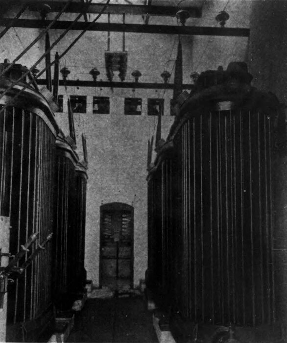
| Fig. 9 -- Interior of the Great Falls Plant of the Portland Lighting & Power Company. |
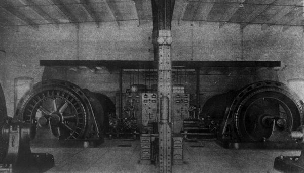
The arrangement of the machinery in the West Buxton plant is unusually logical and conduces to simplicity of operation. The main and exciter turbines are of the horizontal immersed type and each unit is placed in a separate wheel chamber, with the shaft projecting through the chamber wall into the generating room where the electrical unit is coupled on. Each of the four main generators is rated at 750 kilowatts, and generates three-phase current at a potential of 2300 volts. The speed is 150 r. p. m. There are two 125-volt, 75-kw exciter units running at 360 r. p. m.
Each of the main turbines is made up of two wheels, having a diameter of 48 ins. and each is designed to develop 1340 horsepower under a 25-ft. head. The wheel chambers in which the turbines are placed are 12 ft. deep and the draft tubes are 13 ft. long. Water is admitted at the ends of the turbine, and the gates are regulated by means of a Lombard-Replogle governor, belt driven from the main shaft. The gate shaft is parallel with the main shaft and controls the gates by means of reach rods. The gates are 48 ins. in diameter and 22 ins. wide. The common discharge from the two wheels of each machine is into a heavy cast-iron box at the center. Below the draft boxes are the draft tubes, which are conical, 10 ft. in diameter at the upper end and 12 ft. at the lower and 13 ft. long as above noted. These tubes are designed to give a velocity of 5 ft. per second at the lower end with eight-tenths water. They discharge into concrete channels which run beneath the generating room to the tail-race.
The over-all length of the main generating units is 41 ft., and each has six shaft bearings, two at the generator and three in the turbine, with an intermediate thrust bearing. The turbine bearings are located one at each end and one at the center in a yoke bolted to the draft box, and are of lignum-vitae. The thrust bearing is three feet long and is provided with four collars. The shaft is y ins. in diameter at the bearings. The flow to the wheel chamber of each of the main generating sets is controlled by three independently operated head gates. There are two main gates and a filler gate for each wheel, all constructed of yellow pine. The main gates are 7 ft. 9 ins. wide and 13 ft. high, and they differ from each other only in controlling mechanism. One may be manipulated under full head and the other only under a comparatively small head when the wheel chamber is nearly full. However, to facilitate the movement of the main gate in starting up a set, a filler gate is provided to be used ordinarily for filling the wheel chamber. All the gates are operated by hand mechanism of the standard worm gear, pinion and rack design, allowing a lift of 13 ft. The exciter turbines have a rating of 100 horse-power, and are of single wicket gate design, 21 ins. in diameter. They are con¬ trolled by individual head gates.
| |||
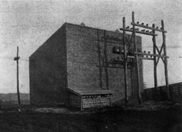
| Fig. 10 -- Main Transformer House in Suburbs of Portland. |
| |||
| Fig. 11 -- Interior of the Great Falls Plant of the Portland Lighting & Power Company. |
The main generators are of the revolving-field type and are designed to carry an overload of 25 per cent for two hours without excessive overheating. They have a full load efficiency of 94 per cent and an efficiency of 91 per cent at half load.
The switchboard and transformers in two banks of three each, are arranged in a row opposite the generating machinery. The transformers are rated at 500 kilowatts, and are oil-insulated and water-cooled. The cooling water is circulated through a coil in the upper part of the transformer tank over the core and surrounding the ends of the windings. The water is taken from the forebay, near the exciter turbines, and carried beneath the floor in two 3-in. pipes, which are connected by a third 3-in. pipe running crosswise under the transformers. This cross pipe is connected with another lateral pipe lying close to the transformers, by risers in which are placed suitable screens. One-inch pipes lead directly to the respective transformers from the secondary lateral pipe. A glass is provided in the water circuit of each transformer so that the circulation is always under observation. From the transformers the discharge pipes lead downward into the tail-race.
The switchboard and apparatus is designed for a current capacity commensurate with the 22,000-volt transmission pressure, and automatically operated oil switches are used on the outgoing lines. There are nine principal panels as follows: One exciter panel, one regulator panel, four three-phase generator panels, one transformer panel and two outgoing line panels.
The entire electrical equipment of the West Buxton plant has been provided by the General Electric Company. All the turbines are of the S. Morgan Smith manufacture, as well as the hoists of the main head gates. The Dayton Globe Iron Works provided the hoists for the smaller gates. The construction of the plant and transmission system has been very materially simplified and expedited through the fact that J. G. White & Company, besides being contractors for the installation, are also the operating managers of all three of the public service properties in Portland, effected by the development. Naturally, decisions as to plans for co-ordinating the new construction with the plants already in use have been reached with little or no unnecessary delay.
