[Trade Journal]
Publication: Electrical Review
New York, NY, United States
vol. 52, no. 6, p. 227-233, col. 1-3
HIGH VOLTAGE INSULATOR MANUFACTURE.
By WALTER T. GODDARD.
PORCELAIN INSULATORS.
The transmission of power by means of electric currents of greater or less voltage began with the introduction of the electric telegraph, and almost the first problem encountered was line insulation. It is of interest in this discussion to note that the first insulators successfully used were of porcelain. From that time to the present the progress has been rapid, the voltage having risen from two or three volts of the telegraph, to a present prospective line voltage of 150,000, and from the lowest to the highest it has always been recognized that best construction involved the use of porcelain insulators.
Fig. 6 shows sectional drawing of a high tension insulator made of several shells nested together and arranged to be fastened together by means of thin joints of Portland cement. This is the conventional design and is used for all voltages, though the size, number of shells, and shape may vary with the voltage. In general, American high voltage insulators are now made of several shells nested together, while European manufacturers still persist in turning complicated shapes from solid masses of dry clay.
The manufacture of porcelain is one of the oldest arts, but only recently has it in any sense been placed upon a scientific basis; In fact, potteries for the production of electrical porcelain exclusively, have not been In existence for more than ten years, and during that time It has been necessary to develop an entirely new system of handling pottery products.
Porcelain for electrical purposes is a mixture of ground flint or silicon dioxide and feldspar, or (K2O Al2O3SiO2) potassium aluminum silicate, raised to vitrifying temperature, that is, to a temperature sufficiently high to melt the feldspar and permit it to unite the particles of flint Into a perfectly homogeneous body of uniform electrical and mechanical strength. The production of electrical porcelain differs from the ordinary pottery product in that, in addition to presenting a symmetrical and flawless exterior, it must possess inherent electrical and mechanical strength.
PROCESS
Flint and feldspar occur in nature as rock which is reduced at the mine by grinding to a degree of fineness comparable to that of flour and of equal whiteness. The modern electrical porcelain potter mixes the proper proportions of flint and feldspar and again grinds the material in the presence of water in order to obtain intimate mixture. The mixture, or as it is dubbed in the factory, "clay," is separated from the excess water, immediately after leaving the grinding mills, by means of filter presses and afterward brought to uniform plasticity by means of kneading machinery.
| |||
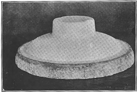
| Fig. 1. Plaster Model of 60,000-Volt Insulator Top. |
| |||
| Fig. 2. Conventional Power-Driven Potter's Wheel and Forming Tool. |
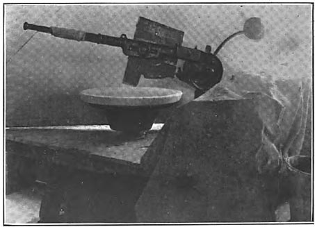
The first step in the construction of an insulator is to build a model 16% larger than the required insulator, and from this model to make moulds of Plaster of Paris. Fig. 1 shows a plaster model of a 60,000 volt insulator top from which the mould in Fig. 2 was taken. Each shell of a multipart insulator is treated in this manner, the inside contour of the mould being that of the desired shell. Fig. 2 shows a conventional power driven potter's wheel upon the top of which is fixed the mould partly filled with clay. The whole device is rotated rapidly and a forming tool whose profile is that of the inside shape of the shell under consideration, is forced into the mass of clay. A few revolutions usually accomplish the desired end and the mould with its wet and plastic clay is then placed in a hot room of approximately 130° F. Within an hour the warm air and plaster mould have absorbed a large proportion of the water in the clay, and the embryo insulator may be removed from its mould and the rough surface, which originally rested against the mould. scraped smooth. The shell, as it may now properly be designated, is set aside for a period of ten days to two weeks in order that all water held by the clay be evaporated. If fired in this state the shell would come from the kiln hard, white and quite rough, of good dielectric strength, but with a surface which would gather and hold dirt and soot and, because of the extreme fineness of the irregularities, be practically beyond possibility of cleaning. For this reason, no other, are the insulators covered with a glassy coating of extreme smoothness, capable of being washed by the gentlest rains. The glazing process is very simple. Immediately before being placed in the kiln, the insulator shell, which in its dry state is about as strong as blackboard crayon, is dipped into a solution of clay and water and by virtue of its dryness absorbs a certain amount. On being heated the clay melts before the body vitrifies and so spreads very evenly over the entire surface. The presence of a small amount of iron In the clay is responsible for the brown color so generally used in this country although any color can be obtained by the use of the proper materials in the glaze. The firing process is entirely a matter of temperature and its complications are ail practical ones due to the large amount of material burned at one time and the difficulty of obtaining exact and uniform heat throughout the kiln.
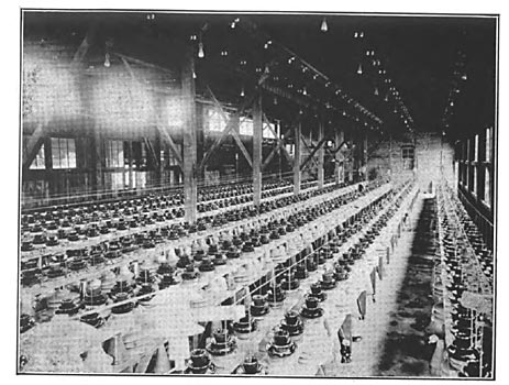
MECHANICAL AND ELECTRICAL TESTING.
The mechanical properties of porcelain are so unvarying that a sample test has always been deemed sufficient. On the contrary it is considered unsafe to permit any porcelain to go into service without testing each piece by means of a high voltage transformer. As will be explained later, the higher voltage insulators are made up of several shells each of which is subject to a high voltage test of 50,000 to 60,000 volts. Fig. 3 shows the connections between the high voltage transformer and insulator shells to be tested. Fig. 4 shows this method as practiced. The table is insulated from the floor by means of porcelain cones in order that high voltage may be applied to the wire imbedded in the table top and designed to make contact with the pans arranged for the reception of porcelain shells. The pans are filled with water and so form one terminal of the high voltage. The other terminal is formed by water poured into the shell, attachment between it and the high voltage over-head conductor being made by means of small chains. By some controlling device in the low voltage side of the transformer, the voltage applied to the shells of porcelain is kept very near to arcing over, in most cases being about 55,000 volts. For ordinary commercial testing the spark gap in air is usually employed when it is desired to ascertain the applied voltage. The number of failures is usually 2% or 3% of the number tested. When porcelain fails electrically the short powerful power arc through the very small puncture hole amounts to practically a short circuit upon the testing transformer and the excessive heat liberated in the porcelain often boils the water and destroys the shell. Once punctured, the porcelain is ruined and can by no method at present developed, be recovered.
 |
| Fig. 3. Connection Between High-Voltage Transformer and Insulator Shells to Be Tested. |
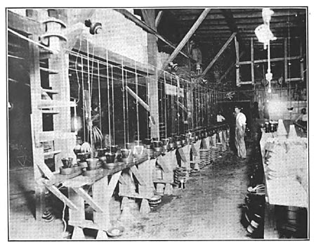
The parts of multipart insulators are united by means of pure Portland cement mixed with water only. After the cement has obtained initial set the insulators are subjected to an assembled electrical test of double line potential for a period of time sufficient to remove all doubt as to the electrical strength of the insulators, usually from three to five minutes. To facilitate cementing and testing, racks, as shown in Fig. 5, are provided so that the operations may be performed with a minimum of handling. There is one very marked advantage in this manner of applying the assembled test voltage, and it is, that the voltage may be put on before the cement is dry enough to permit handling of insulators so in case of failure by puncture of any shell, it may be separated from the others without injury, a thing absolutely impossible once the cement becomes dry.
DESIGN OF HIGH VOLTAGE INSULATORS.
Insulators for the lower voltages call merely for the introduction of sufficient good material, between line and supporting structure, to prevent destructive leakage. For voltages up to 20,000, little or no difficulty is experienced in securing satisfactory insulation, but above that voltage it becomes not only necessary to have good material in plenty, but it must be properly distributed in order that the danger of puncture and severe leakage be reduced to a minimum. The manufacture of good porcelain from a mechanical standpoint forbids that it be made so vitreous as to resist a puncture test of 65,000 to 70,000 volts over 1/2" or 5/8" thickness. It is vain to attempt to gain greater dielectric strength by increasing thickness since inherent cracks in thick pieces really reduce the effective electrical strength to that of 1/2" or 5/8" porcelain. Accordingly, it has come to be recognized as best practice to make no attempt to manufacture the higher voltage insulators in a single piece, but rather to secure great electrical strength by multiplicity of parts. Though entirely possible to construct 30,000 volt insulators of one piece and still safely apply a double potential test, years of experience have demonstrated that a multipart insulator is much less liable to fail entirely, when struck by stones or bullets, than are single piece insulators and so prevents complete shut-down of the transmission line. By far the larger proportion of shut-downs on the modern transmission line come from mischievously broken insulators. It is for this reason as well as for greater normal safety factor that engineers are selecting multipart insulators at higher cost, even for the lower voltages. In general, two-piece insulators are used for from 10,000 to 30,000 volts, three pieces for from 30,000 to 50,000 and four pieces for the 66,000 and 70,000 volt lines now in operation. Above 70,000 volts the underhung or suspended insulator works out most economically and, for entirely different reasons, 8 or 10 shells of porcelain are introduced.
| |||
| Fig. 4. Method of Testing Insulator Shells. |
| |||
| Fig. 5. Testing Insulators While in Process of Cementing and Assembling. |
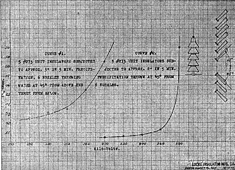
Considerations of puncture strength are the first concern of the designer. As before noted, good electrical and mechanical porcelain should be made of not more than 5/8" thickness with an ultimate electrical strength of not more than 70,000 volts. To gain greater electrical strength it is necessary to introduce other shells which continue to add a proportional dielectric strength up to about 220,000 volts, at which point the curve gradually tends to become flat and becomes very nearly so at 300,000 volts, so that it is apparently useless to utilize more than 5 shells unless some other condition is introduced. With this to start with it is a very simple matter indeed to provide economical insulators for any voltage up to the point where difficulty of manufacture begins to interfere with progress. The 10,000 and 20,000 volt insulators have little to do with puncture strength provided, of course, that the porcelain is of good quality, and so the question reduces to an estimate of necessary leakage distance and carrying capacity when subjected to an artificial rain approximating the worst conditions to which the insulator will be subjected. This is not so simple as appears on the surface, for while an insulator may behave admirably under & downpour of unprecedented intensity, it is vain to expect Nature to limit herself to a vertical, or what is technically known as a 45° rain, nor does she stop after five, ten, or fifteen minutes, but is much more likely to accompany the downpour with sufficient wind to blow the rain very nearly horizontal, and to persist for any length of time. Under such conditions the insulator either meets its Waterloo or shows its mettle in the first fifteen minutes, for at the end of that time all portions, except possibly the inside of the innermost shell, have become thoroughly wet and the surface leakage comes into play. As is well known, the persistence of any arc of definite length has to do with the voltage impressed and the current flowing, and the failure of an insulator is of course amenable to the laws which govern arcs. A designer should assume that his insulator will sometime become wet all over and should provide sufficient leakage resistance to prevent any considerable amount of current flowing, a small amount merely tending to dry off the insulator whereas a large amount would quite likely start a disastrous arc under the shells and completely destroy them by its heat before extinguishing itself. Such an insulator represents very nearly the ideal and it is regretable that so few lines are equipped with insulators of so great a margin of safety. It must not be forgotten that only once or twice a year are Insulators called upon to perform extreme duty, in fact, the insulators of most lines are for the greater part of the time working very inefficiently, probably at not over 20% of their rated capacity.
The next best thing is to provide as much dry surface as possible under average storm conditions and, to this end, it is of value to note the progressive wetting of an insulator under rain. It is customary to mount the insulator well above the cross-arm, so that all its shells are far removed from water spattering up from the arm. Assume an insulator of conventional design of three or four shells. The top becomes dripping wet at once and the film of water held on the surface carries line potential to the outmost diameter. A certain amount of rain gets by the top and strikes upon the lower shells, part spattering upward and part downward, depending upon the angularity of precipitation. That portion which spatters upward soon wets the entire under surface of the shells above and in this manner the potential is carried down to the lowest projecting shell. At this point the leakage path is broken, due to the fact that beneath the lowest shell there is no surface from which spattering may occur and consequently it remains dry, but under this condition the central shell of the insulator is carrying the total strain both as to puncture strain and against flash over. Fig. 6 shows clearly the effect of spattering, the double line indicating the surfaces covered by a film of water and thus carrying line potential down to the bottom of the lowest projecting shell. It may be further noted that between this double line, or line potential, and the pin, there is but one effective shell which has been subjected to but 60,000 volt test, and lines of very moderate potentials have strains of this magnitude between line and earth. The shells must, of course, remain wet till the storm is over or some drying-action is introduced. If the gap between the edge of the lowest shell and the pin is small enough a small arc will be established, thus completing the circuit and permitting a leakage current, formerly held in check by the dry inner surface of the shell, to flow, though limited in volume by the relatively high resistance of the pure water film covering the insulator. This leakage current heats and vaporizes the water film, its first action naturally being where the current density is greatest at the neck of each shell, where, fortunately, the surface is not subject to the direct force of the rain. Since potential is In no way concerned with resistance, the thinnest and consequently highest resistance film of water is sufficient to inaugurate the drying process, so that an insulator in service cannot be caught unawares and, if properly shaped, can care for itself.
 |
| Fig. 6. Sectional Drawing of High-Tension Insulator. |
 |
| Fig. 7. A Protected Shell Which Can Not Easily Become Wet. |
 |
| Fig. 8. Straight Shell Insulator. |
From the foregoing it will be seen that the dielectric strength of the inner shell of any multipart insulator and the distance between its lowest edge and the supporting pin, are of utmost importance, the remainder of the insulator serving as little more than a resistance in series or leakage distance to limit the amount of current which may flow when arcing takes place. To provide against the first requisite it is merely necessary to introduce a protected shell which cannot easily become wet. This is shown in Fig. 7, as is also the great distance between pin and edge of lowest shell. What has been said applies to insulators as it is necessary to build them to meet mechanical conditions imposed, and it is the mechanical characteristics, not the electrical, which influence their cost. Were it possible to make porcelain wire of great strength, an insulator of perfect certainty of action could be produced at minimum cost. An insulator should not be regarded as a barrier to current, but rather as a high resistance path between line and earth, and its design should aim to serve this purpose. Referring again to Figs. 6 and 7 it will be seen that as far as the ultimate strength of the insulator is concerned, the shape of the upper shells is of no moment, since they serve as series resistance only. There are reasons however why straight shells should be used and others equally good why curved shells should be introduced, but the adjustment between the desirable points of one and the desirable points of the other call for fine discrimination. Figs. 6 and 8 show straight and curved shell insulators subjected to a 45° storm which spatters most vigorously in the direction shown by the arrows. Of these two insulators the straight shell would probably keep dry the longest since a large portion of the falling water is deflected away. On the other hand, the distances A-B, C-D and E-F are much greater on the curved shell type permitting it to carry much greater potential previous to its becoming wet all over than could the insulator of the straight shells. The curved shells will thus be better able to take care of sudden potential rises when partly wet than will those of the straight shell form. However, this partly wet condition does not last long, as there is often enough precipitation to entirely wet the shells, and it is only then that the insulator can be assumed to be operating under full load, a condition for which it should be designed.
The foregoing applies equally well to low-voltage insulators, though up to 40,000 volts it is hardly necessary to provide protection for the innermost exposed shell since its own strength is entirely ample.
So much space has been give to discussing the value of the insulator when under rain that its pleasant-weather qualities may seem to have been over-looked, but there are sudden and severe demands upon the insulator in the pleasantest weather mainly from lightning and switching. When a rise of potentional far above normal working voltage comes upon a perfectly dry insulator, the stress between line wire and pin is very sensibly increased, and that this stress shall not be too severe the distance between line wire and pin should be made ample by the introduction of several shells of porcelain. The specific inductive capacity of porcelain, or its flux-carrying capacity, is a perfectly definite thing, compared to air about 4.4, so that for any given potential, area of contact and thickness of shell, the density is determined.
| |||
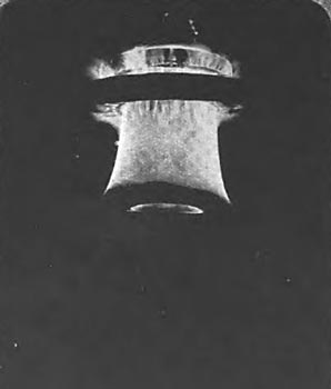
| Fig. 9. Two Porcelain Shells Subjected to 100,000 Volts. Photographed by Their Own Light. |
| |||
| Fig. 10. Break-Down of Central Shell. |
| |||
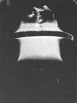
| Fig. 11. One of the Largest Insulators Ever Built, in Distress at 175,000 Volts. |
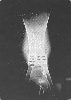
Porcelain, however, unlike some dielectrics, gives due notice when overburdened, by a pale violet light over its entire surface. Fig. 9 shows two porcelain shells subjected to 100,000 volts, their very evident distress being photographed by their own light. Fig. 10 shows better than can words how it is that so many lines have trouble with central shells breaking down. The designers in this case had failed to provide against the great concentraion which will in time disrupt the finest porcelain. Fig. 11 shows one of the largest insulators ever built, being tested at 175,000 volts, its distress being very evident and presaging early break-down. How very little it takes to correct this fault is easily seen by a moment's contemplation of the fact that the stress within the porcelain will vary inversely as the square of the distance between terminals. From these experiements it appears that to avoid getting into serious trouble when potentials somewhere near the arcing over capacity of the insulators are applied, it is necessary to provide considerable body of insulating material between line and pin.
Mechanically, insulators can be designed for any load by the proper dispostion of material. Good electrical porcelain has a crushing strength in excess of 15,000 pounds, and tensile strength ranging between 1,500 and 2,000 pounds per square inch.
The latest development in excessively high-voltage insulators is but a reversion to a type long since discarded by lower-voltage engineers, i. e., the underhung or suspended type of insulator. Reference to old telegraph manuals shows that the first English telegraph systems were insulated by underhung insulators of bowl-shaped porcelain. To come down to the present, all our trolly wires are suspended below the supporting device. For years wireless telegraph companies have been using strain insulators in series, so the newest high-voltage insulator is, in reality, the oldest. Fig. 12 shows a modern development of the underhung insulator of five units designed to operate at 100,000 volts, grounded neutral, with a factor of safety of four. It is intended to allow the conductor to swing freely in any direction.
The reason for using suspended insulators is largely a matter of cost since it is entirely possible to build porcelain insulators of the conventional type of sufficient size to successfully operate at any voltage, but the extreme height and diameter of a pin-type insulator for 100,000 or 150,000 volts makes the cost prohibitive. A suspended type of insulator has several advantages which it is well to understand before going into details of design. Of paramount importance is the unit formation making it possible to increase the effective insulation whenever it is desired to raise the line voltage or wherever it seems desirable to present extra leakage surface because of salt fogs or smoke from railways and factories. Many lines start operation at much lower potential than designed for, because the initial load is light and the potential need be Increased only when regulation demands it. With the pin type of insulator there is no alternative but to invest at the start in the largest insulators which the line will ever need, whereas in the suspended form, additional units may be introduced whenever the growth of power business warrants an increase in potential. In the pin type of insulator the nearness of line wire and pin must always prove a weak point for lightning assault as well as an aggravator of line-charging current difficulties. The suspended type gets away from both difficulties by a wide separation of line conductor and supporting structure. Incidentally the position of the conductor below the cross-arm permits the supporting structure to act as a lightning rod, and so to relieve the line of much lightning stress.
Mechanically, provision must be made to prevent the swinging conductor from coming too near the tower structure, but the extra length of cross-arm necessitated by this feature is more than compensated for in cost by the fact that there are no twisting strains upon the arm.
Insulator unit formation presents another very positive advantage in the matter of breakage. When a shell of a pin type insulator becomes cracked or broken, the whole device is rendered worthless, as it is utterly impossible to break the cement joint forming the bond between shells. Further, the cracking of a shell, especially an inner shell, may cause immediate shut-down or at least shut-down during the first severe rain storm. On the contrary, the breaking or cracking of one of the shells of a suspended unit type insulator takes away but that one unit from the series; thus, in the case of a 5 unit 100,000 volt insulator, a broken unit reduces the total strength but 20%.
With these very evident advantages it is small wonder that with voltages reaching toward 100,000, the underhung insulator should be adopted. The first question, that of "mechanical strength, was promptly disposed of by so designing porcelain parts that strains were all compression. The next question, that of electrical strength under normal operating conditions, was not so easily solved. In the first designs, single shells of porcelain of 5/8" thickness were used, but when a series of 5 such shells was subjected to a 300,000 volt test, a new condition was found to have been introduced in the way of a potential rise around the first units, and it was found by repeated test that any sudden application of potential, or even change in potential already applied, would puncture the end shells, which if made of economical pottery size, i.e., 14" diameter, would have a flash-over potential of approximately the ultimate puncture strength. This condition analyses somewhat as follows: The shells and metallic connecting links form a condenser of certain definite capacity, which for the sake of analogy may be likened to a mass of rubber or other elastic material. Carrying out the analogy, the rubber is struck a smart blow with a hammer. The surface struck, and layers of material immediately adjacent to it, feel the force of the blow most severely, and if the mass be thick and of great inertia, the force of the blow is barely perceptible on the surface opposite to that where the blow was struck. Moreover, the elastic material is no sooner struck and compressed than it attempts to return to its normal shape. This property of inertia is duplicated in the action of condensers in series, call it what you wish, dielectric hysteresis or anything else, the effect is there, and if proper precautions are not taken, the outer layer of resisting medium, in this case a porcelain shell, will be disrupted. Unquestionably the dielectric strength of the unit must be increased, and the proper method is by supplying an inner protecting shell so that the puncture strength of the built up unit shall be far in excess of its flash-over potential. A unit so constructed is practically indestructible, and will carry continuously its flash-over potential without heating or its surface being covered with static, which impairs the efficiency by shortening the leakage path. Under normal operating conditions the end unit is the only one which is subject to unusual strains, but the failure either by mechanical breakage or arcing over, may at any time put similar strain upon other units, so It is a wise provision to guard all shells against possible puncture. Having made the unit secure against puncture, the next concern is with leakage distance, which must be made of sufficient length to prevent any considerable current flow when the entire surface is covered with a thin film of water. Here again, cost governs, since the unit construction permits the use of a few large or several small parts. As noted before, 14" is an economical size for the potter to produce, and as the metal parts are the same for any diameter of shell, it is this size which returns most in insulation for each dollar invested. Fig. 16 shows the construction of a unit of a modern 100,000 volt insulator. The shape of the shells is not of importance since in testing to flash-over under working conditions, pains were taken to wet all surfaces thoroughly and so produce artificially the worst possible conditions; but it must not be taken for granted that leakage over an insulator is a desirable thing, in fact, the time when an insulator will leak sufficiently to dry itself should be postponed as long as possible by logical designing. To accomplish this it is of course necessary to permit as little water as possible to spatter on the under side of the shells, and this is best effected by deflecting the water away rather than toward the insulator. If this were the only thing to consider, the best shape of shell would still be in question. There are, however, other conditions. When, in the course of a severe storm the under as well as the upper shell surfaces have become thoroughly wet and leakage has commenced, the first spot to become dry is the inside of the innermost shell at the point of smallest cross-section, A, in Fig. 12, and a small arc is at once formed which, if allowed to persist, will heat and crack the shell. To avoid this the edge of the shell is brought down till the point, B, is of such a distance as to induce the arc to play between B and the malleable-iron cap, C, of the unit immediately below.
 |
| Fig. 12. Showing the Progressive Breaking Down Between the Beginning of Actual Leakage and the Maximum Arc. |
An arc of considerable magnitude may be maintained between these two points without heating the shells above sufficiently to cause cracking, since the air currents established tend to keep down the temperature. Current sufficient to support an arc between B and C will, unless the rain be very heavy indeed, dry a portion of the surface between D and E which causes the arc to straighten out, and if there be sufficient current at high voltage, it will eventually be held between the conductor and the supporting structure. Fig. 12 shows the progressive breaking down between the beginning of actual leakage and the maximum arc, which is not sufficiently close to the insulator to damage it. With only 500 kilowatts at 300,000 volts available, the above deductions were found to be true and the ability of the design to rid itsel of arcs formed upon it demonstrated beyond question. The suspended insulator thus becomes an automatic relieve valve which may be relied upon to discharge the line safely and effectively without damage to itself or serious interruptions to the service.
 |
| Fig. 13. --Construction of A Unit of A Modern 100,000-Volt Insulator. |
| |||
| Fig. 14. Curves Showing Action of A Five-Unit Insulator Under Partially Wet and Wholly Wet Conditions. |
The curves of Fig. 14 show action of a five-unit insulator under partially wet and wholly we condiitons, and permit of estimate as to probably operating safety factor. The current values which were used in plotting these curves were obtained by means of a Thompson voltmeter, calibrated in amperes, introduced into the high-voltage winding at its middle point. One side of the instrument was well earthed in order to protect the operator. Voltages were gotten by means of a needle cap carefully protected from air currents.
The method of utilization of freely suspended insulators may be of interest. Figs. 15 and 16 show in detail how this dead-ending is accomplished, and how the line is passed from one end-clamp to the other.
 |
| Fig. 15. Method of Suspending. |
The underhung system of insulation speaks out with pleasing directness and simplicity, and its comparative cheapness provides for its wide adoption for the high-tension voltages. The cost of such insulators, at present manufactured, ranges from $1.50 to $2.00 per unit, depending on the nature of the fittings. At least two fourteen-inch units would be required for 60,000 volts, and as a good 60,000-volt insulator can be secured for prices ranging between $1.70 and $2.30 each, the question of the use of suspended units for voltages below 75,000 to 80,000 is largely part of safety factor and investment.
 |
| Fig. 16. A Detail of Dead-Ending. |
The foregoing has given little which could be used in the determination of the number insulator to use for any particular voltage, and it is quite in point to add here that every case is special. Insulators well suited to one locality are out of reason, in safety factor provided, for use elsewhere. A single transmission line of less than 100 miles in length may easily pass from high, clear mountain air to foggy, smoky, surroundings which are a constant menace to continuity of service. Again the cost of complete immunity may well be balanced against cost of possible shut-downsa point well illustrated in the line operating between Niagara Falls and Syracuse, all branch lines of which are equipped with much smaller and consequently cheaper insulators than those upon main lines.
It is not intended to convey the idea that every line should have a special insulator, but that the characteristics of the proposed line should be made known to the designer in order that all points may be well guarded against. It is quite likely the resulting recommendation will be upon an old established type of which all characteristics are known, and though Its use for any specific case may not call into use all it is capable of, it will quite likely prove cheaper to produce a standard article of larger size than to make a special design of just sufficient capacity.
A forecast of the future of any business, though never safe, is always interesting.
Concerning the highest practicable voltage, without reference to anything but insulators, It is safe to say that insulators for the heaviest mechanical strains and for the highest electrical stresses can be manufactured at moderate cost, so that limitations of transmitting voltages must at the present time be looked for in other directions than in insulator design, porcelain insulator design in particular.
Wherever the word insulator has been used, porcelain insulator is implied, for no other material has been so universally used in the past, and none gives such promise for the future. Its one bad characteristic, that of brittleness, is overcome by good designing: otherwise, the material is very nearly ideal for it is cheap and comparatively easy to manufacture. Of prime importance is its permanency, and of no other manufactured dielectric can as much be said. Porcelain is made under extreme conditions of heat which effects the cementing together of stable elements which have been in their present form for thousands of years, and under the conditions at present obtaining on the surface of this planet, will remain unchanged. Moreover, the porcelain is homogeneous and of a uniform texture throughout and consequently of uniform specific inductive capacity throughout, so that electrical strains are evenly distributed. On the other hand, organic materials are subject to very rapid deterioration; many unite with oxygen at ordinary temperatures or are attacked by rain water in a very short time. Heating by condenser action also aids in oxidation processes and hastens the end. A favorite method of insulating against low voltage is by means of compositions of rubber, gutta-percha, pitch, asbestos, ground mica, shellac, and the like, but the result is always the same, and a moment's contemplation of the reasons of failure would seem to argue against their use for permanent exposed insulation.
The past is full of unhappy experiences in the attempt to insulate high voltage lines with glass, rubber, mica, etc., and occasionally an engineer is found who is willing to erect lines of high pressure on insulators of material other than porcelain, but such engineers are so rare as to make it safe to say that, as a permanent dielectric, porcelain, to-day, stands alone.
