[Trade Journal]
Publication: Western Electrician
Chicago, IL, United States
vol. 42, no. 13, p. 247, col. 1-2
High-potential Insulator of Novel
Construction.
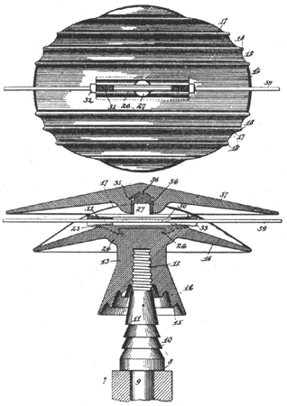
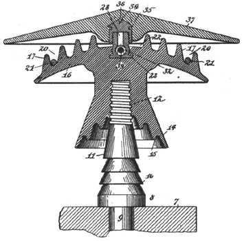
An insulator for high-tension lines which embodies many novel features has been invented by Louis Steinberger of New York city, who has been granted a patent on the invention. The principal feature of the insulator is the provision of two hoods between which the line wire is clamped, each of these hoods being of special construction, as is also the clamping device. The accompanying diagrams show the general design of the insulator. Fig. 1 is a central longitudinal section, above which is shown a plan view of the lower hood. Fig. 2 is a transverse central section taken at right angles to the one shown in the lower part of Fig. 1.
 |
| Fig. 1. High-Potential Insulator. |
The supporting pin (9) fitting into the cross-arm has a number of petticoats (10) and a threaded stem (12), all in one piece. Upon this stem is screwed the main insulator body (13), which is shown with a triple petticoated base. The upper portion of this insulator body is spread out into the hood (16), which has on its upper surface a series of longitudinal ribs (17) of substantially arcuate form, each rib being parallel with the general direction of the wire and extending from edge to edge of the hood. Each rib terminates in beads (18) protruding slightly beyond the edge of the insulating hood. Between these beads are concave recesses (19). It is said that this arrangement facilitates the dripping of moisture which gathers, in streams and flows through, longitudinal channels (26) parallel with the wire, being discharged upon opposite sides of the wire so as to miss the cross-arm. Auxiliary wires (21) may be placed in these channels, in cases of emergency or whenever desired, the weight of the wires retaining them in position.
 |
| Fig. 2. High-Potential Insulator. |
A wide channel extends across the center of the hood. A plate of metal (23) is provided upon its under surface with hooks (24) directed toward each other and imbedded within the body of the insulator hood, thus constituting anchorages which prevent the removal of the plate. This plate is provided with a superposed tubular portion having a slot extending throughout its length. Lugs (27), each of substantially semi-cylindrical form, are mounted integrally upon opposite sides of the slot and together constitute, a divided stem, the two parts of which are separated by a slot (28). The inner ends of the tubular member are provided with threads, and the core (30) extends entirely through the latter and may be closed by tubular clamps (31), threaded externally. Each of these clamps is provided with a square head (32) and with a slot (33) extending entirely through the clamp. The clamp is preferably made with a tapered body, as indicated.
A screw cap (34), provided with anchorages (35) and (36), is imbedded within the upper or sheltering hood (37), in such a manner that by turning this hood the screw cap may be connected with or disconnected from the divided stem (27). By aid of this screw cap the sheltering hood may be removed or replaced at will. This hood covers the entire insulator and largely shields it from the elements.
In setting up this insulator the body portion is screwed upon the upper end of the insulator pin and turned to such an extent that the plate (23) and its tubular portion are parallel with the general direction in which the wire or cable (39) is to lie. The wire may now be lifted into position or threaded through the tubular member. The cored guard clamps (31) may next be screwed into the ends of the tubular member. Preferably, however, these cored plugs are placed approximately in their respective positions before the wire is placed in position. The plugs are turned so that their slots (33) are uppermost and register with the slot (26), and the wire is raised and simply dropped into the slots. The guards are then turned half a revolution (see lower part of Fig. 1) so that slots (33) are now downward, whereby the wire is firmly and securely locked within the tubular slotted member and cannot be dislodged or removed except by unscrewing the slotted clamping members. The sheltering hood is next screwed into position. This squeezes together the semi-cylindrical portions (27), thereby still further augmenting the locking action of the clamps and effectually preventing any movement whatever of the locked parts.
The invention is not confined to any particular material.
