[Trade Journal]
Publication: Electrical Review - London
London, England
vol. 62, no. 1586, p. 675-676, col. 1-2
SOME NOTES ON HIGH-TENSION INSULATORS FOR OVERHEAD TRANSMISSION LINES.
By C. J. GREENE.
IN spite of the large amount of overhead transmission work which has now been carried out in this country, the knowledge acquired in connection with porcelain insulators seems to be extremely small and unsatisfactory. No reliable data appears to have been collected in connection with the working of various sizes and types of insulators under the varying conditions of our somewhat trying climate, and, consequently, we are still in the dark as to what a really good, safe, and at the same time inexpensive, insulator should be for working under certain fixed conditions.
In consequence of this lack of knowledge, we are most of us frightened of insulators, and there is no doubt bat that, on nearly all overhead lines erected up to date in this country, the size and cost of the insulator has been needlessly great. It is no doubt due to this cause that the breakdowns on these systems have been so few and far between.
That the factor of safety of the insulators now in use should be so high is, of course, most unfortunate from the point of view of those who are seeking knowledge about them. No amount of laboratory or similar tests are equal to the test of time and actual service conditions in matters of this sort ; and if our insulators are so good that they never break down, we shall never find out what are the limiting dimensions or weak points in design, unless some philanthropic manufacturers will carry out a series of tests under all possible conditions of weather.
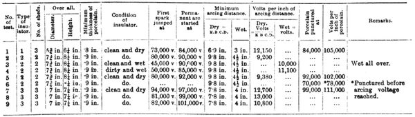
| |||
| Table 1. |
That different ideas should exist is, however, on the other hand, a very good thing, as to attempt to standardise too early kills all progress and originality; but this is no reason why, with the experience we now have, we should not benefit by our knowledge, rejecting the obviously defective designs and preserving the good ones, and settling within limits what the design and size should be.
This would prevent contractors and manufacturers tendering insulators which. vary over 100 per cent. in price and size for working under exactly the same conditions, and it may here be noted that, as a rale, the consulting engineer prefers to leave this responsibility entirely to the contractor.
Having prefaced this article with the above brief remarks, the writer proposes to give the results of a series of tests, which he has recently been able to make at 100,000 volts, on some porcelain insulators of British manufacture, and to attempt to draw some conclusion which may be useful ; also to give some statistics of standard insulators of other countries, analysing their dimensions and factors of safety in the light of the results obtained in the tests.
SPARKING DISTANCE.
Before carrying out the tests on the insulators, it was thought desirable to prepare a table of sparking distances, and for this purpose two brass rods mounted on high-tension insulators were connected to the H.T. terminals of the testing transformer, one of the rods being earthed. The low-tension side of the transformer was connected to an intermediate step-up transformer, which in turn was connected to the terminals of a supply company's mains, a water resistance to regulate the voltage being inserted on the low-tension side. The shape of the E.M.F. wave approximated very closely to that of a sine curve, and the voltages recorded throughout the experiments were the R.M.S. volts.
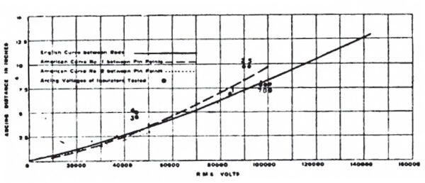
| |||
| Fig. 1.--Curves of Sparking Distances. |
The diameter of each rod was 3/16 in., and the ends of the rods were simply rounded off with a file, so that no sharp point or edge was presented. It was thought more desirable to obtain the sparking distance between these rods than between the conventional pin points or balls, firstly, because the results obtained would approximate more closely to practice; and, secondly, for the purpose of checking the distances so obtained with previous tests carried out between the conventional points or balls.
The method adopted was to set the rods a definite distance apart, and then run the voltage up till a series of sparks, or a permanent breakdown of the intervening air took place, when the voltage was recorded for that particular distance.
A number of readings were taken, and it is interesting to note that the results given, on the average of the readings, showed practically no variation for any given distance.
The results so obtained are plotted on the accompanying curve, fig. 1, and so as to serve as a check on the results so obtained, two other curves, both obtained by experiments carried out in America, are plotted. Curve No. 1 is that published by the American Institution of Electrical Engineers, and curve No. 2 is that obtained in a series of most careful and valuable experiments carried out by Mr. H. W. Fisher, and presented to the Electric Power Transmission Committee in 1904.
It will be seen that the curve between rods, as given by the writer, agrees very closely with the curve obtained by experiments made in America, falling below the curve obtained between pin points at the higher pressures, which is, of course, what would be expected.
The black points which are numbered represent the voltages at which arcs were set up between line and pin for the arcing distances of the various insulators tested, and they will be referred to later on. In the meantime it may be noted that they fall fairly well on the curve of sparking distances.
TESTS ON INSULATORS.
Three types of insulators were tested, the shape and dimensions of each type being shown accurately in the accompanying drawings. All the insulators were of English and of best quality vitrified porcelain, specially made for use with extra high-tension lines. All surfaces were well glazed. Insulator No. 1 was a dark brown colour, and insulators Nos. 2 and 3 were white.
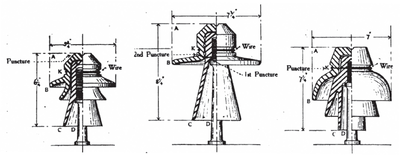 |
| Fig. 2. |
In every case the pin was earthed and the pressure applied to a soft copper binding wire bound round the side groove of the insulator, the end of the wire after being fastened to the insulator, being carried vertically upwards so as not to reduce the arcing distance to the pin. The arcing distance during the test was, therefore, in every case K B C D for the dry insulators. The results obtained are summarised and scheduled out in Table I.
