[Trade Journal]
Publication: American Institute Of Electrical Engineers
New York, NY, United States
p. 529-538, col. 1
COMPARATIVE TESTS OF LIGHTNING PROTECTION DEVICE
ON THE TAYLORS FALLS TRANSMISSION SYSTEM
BY J. F. VAUGHAN
Recent Institute discussions have brought out a decided difference of opinion on the value of certain lightning protective devices and have expressed a demand for positive data on line protection especially. This paper furnishes data obtained last summer on an operating line experimentally equipped with various protective devices. The results are of especial interest in being actual records made by means of tell-tale papers applied not only to the station protective devices but also to those on the line, and even to the line insulators themselves throughout the system.
When the transmission from Taylor's Falls to Minneapolis, Minnesota, was built in 1905, local conditions demanded the best lightning protection available. The line ran southwest from the power house a distance of about 40 miles through a rolling country, partly wooded and full of lakes and swamps. It lay in the natural path of thunderstorms forming to the northwest of Minneapolis. Investigation indicated a zone about 9 miles long near the middle of the line that was especially subject to severe lightning, and the splintering of six poles in different parts of this zone before any wire was strung suggested the necessity for special protection at exposed points against direct stroke.
On account of the wide divergence of opinion on the subject of lightning protection, and the impossibility of reconciling the conflicting results of practice, it was decided to try out on the Taylors Falls System all existing devices of promise and such others as might be devised, in order, by comparing them in actual service, to work out some effective scheme for future protection.
Description of system. Current is generated by four 2500-kw., 2300-volt, 60-cycle, three-phase water-wheel driven machines, each operated as a unit, with a bank of three 900 kw. transformers connected delta-delta and stepping up to 50,000 volts. The pressure is stepped down at the main sub-station on the outskirts of Minneapolis to 13,800 volts for local distribution and transmission to a steam and water power local plant in the city. Automatic time-limit relay oil switches control the lines and transformers at all three plants.
 |
| Fig. 1 |
 |
| Fig. 2 |
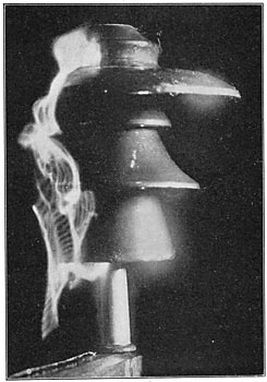
The transmission consists of a single line built on private right-of-way using Idaho cedar poles of 45 ft. standard length, carrying three 0000 semi-hard-drawn copper cables supported on 14 in. four-part porcelain insulators arranged on a 6-ft. equilateral triangle with the apex at the pole-top (Fig. 1). The insulators (Figs. 2 and 3) were originally selected from a number of samples, including five others of the writer's design, as the only insulator obtainable which, under driving rain test, showed properly distributed electrostatic stress without concentration on any one part. These had already proved unusually rugged, as shown by two years' use, without any electrical failures on 75 miles of 57,000-volt transmission on the Puyallup system in the state of Washington. The insulators are supported on iron-pipe pins cemented into them and bolted to the pole-tops or set into the cross-arms. The line also carries a pair of telephone wires on an arm 7.5 ft. below the transmission arm.
| |||
| Fig. 3 |
The telephone system consists of a metallic circuit of No. 10 copper mounted on porcelain insulators of the same design as the ordinary double petticoat glass type. Instruments are permanently connected at the power house, sub-station, and inspector's cottage at the middle of the line, and booths provided at various points for tapping in inspectors' portable instruments.
Station protection. For protection of the power house and sub-station low-equivalent multigap arresters and oil-insulated choke-coils were installed, supplemented at the sub-station by a set of experimental aluminum cell-type arresters connected to the entering line through a small number of arrester gaps in zigzag arrangement, set so as to be normally active.
The transformers at all stations were further protected on their low-tension sides by static discharge gaps.
LINE PROTECTION.
Horn-type arrester. Three types were installed, one at each end and one in the middle of the line, primarily to pass off disturbances of unusual magnitude, and also to experiment with the different forms.
The sub-station arrester consisted of a single gap on each phase, arranged with a sheaf of water jets forming series resistance to ground. This required too much water and was replaced by tanks of water with terminals of carbon rods in fiber tubes (Fig. 4).
 |
| Fig. 4 |
 |
| Fig. 5 |
 |
| Fig. 6 |
The power house arrester had two gaps in series between each phase and ground, with the second gap shunted by carbon terminals placed in the river (Fig. 5).
The Hugo arrester, at the middle of the line, was built on the selective resistance principle, with three gaps in series on each leg, the second and third gaps being shunted by water-box resistances (Fig. 6).
Overheaded grounded wires. Four types were erected in the nine-mile zone in 0.5 mile lengths, alternating with 0.5 mile lengths of unprotected line as follows:
Type A. Two wires mounted on a cross-arm 5 ft. apart on either side of the top line wire and about 18 in. below it (Fig. 12).
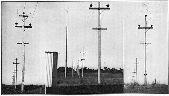
Type B. Two wires supported on standards of 1.25 in. iron pipe 6 ft. apart and 18 in. above the top line wire (Fig. 7).
Type C. One wire on knobs attached to the pole near the center of the delta (Fig. 12).
Type D. Two wires in the same position as in Type B, but supported on pipe pins set in the ends of a cross-arm attached near the top of the pole.
In the above constructions the grounded wires were of No. 6 hard-drawn copper. The ground connections were of 0.5 in. by 0.0625 in. galvanized iron ribbon wire at every fourth pole and the ground made by 0.75 in. galvanized iron pipe driven to moist ground.
| |||
| Fig. 7 |
Lightning-rods. Four types were used, erected in the nine-mile zone in sections from one to two miles long, separated by unprotected sections as in the case of the grounded wire constructions as follows:
Type A. Rods of 1.25 in. galvanized iron pipe attached to the poles and extended by tridents of copper wire reaching 6 ft. above the top line wire (Fig. 7).
Type B. Rods of 1.5 in. galvanized iron pipe mounted on separate poles 20 ft. to one side of the transmission line and topped by tridents of copper wire extending 25 ft. above the top line wire. Rod poles were spaced at the centers of alternate spans (Fig. 7).
Type C. Same as Type B, but spaced three rods to four spans.
Type D. Same as Type B, but spaced 1000 ft. apart.
Ground connections were made as on grounded wire construction, but with two grounds for each rod pole, one at the base of the pole and the other 20 ft. or more away, to insure especially wet ground and to increase the discharge area.
Telephone protection. Each permanent and temporary telephone connection was made through a one-to-one repeating coil and discharge gaps to ground set to break down at about 900 volts.
Recording devices. All station arresters were provided with tell-tale papers. To determine the character of disturbances, their extent, magnitude, and effect on line and apparatus, ground connections of all protective devices were provided with gaps for the insertion of tell-tale papers.
To study the stresses on the line insulation throughout its length and the behavior of the insulators, each insulator pin at every third pole was grounded through a separate ground wire and tell-tale box (Fig. 7), supplemented by choke-coils shunted with tell-tale gaps cut into the line wires at various points.
After a number of insulators on grounded pins had been damaged, the pin grounds were removed from four sections of about one mile long each, separated by one-mile sections left grounded, to prove whether the grounding was in any way responsible for insulator failures.
Records. The following records were kept:
A. Weather conditions shown by United States Weather Bureau reports, and reports of observers along the line.
B. Storm occurrences and data furnished by local men in charge.
C. Operating and special reports of interruptions to service and damage to system.
D. Tell-tale papers collected after each storm.
E. Graphic analysis of tell-tale papers for each storm.
Operation and results of first season. The transmission system was started up in December, 1906, and lightning protection records carried through the following summer. The lightning season opened late in March and lasted into October. Thirty-two storms occurred during this season within reach of the line.
The following tabulation gives data on the storms and damage to system, or interruptions to service.
The tabulation shows that in 17 out of the 32 storms the service was interrupted and 8 of these storms caused damage to insulators, while only one storm affected the station apparatus; this was due probably to a defect in a transformer bushing, but was not sufficient to interrupt the service. Out of 42 insulators damaged, only 3 were punctured, the rest being shattered.
The plan and profile of the line (Fig. 8) show the distribution of damaged insulators on the line and indicate their phases, location on pole or tower, etc.
The following tabulation further analyses insulator damage.
