[Trade Journal]
Publication: American Institute Of Electrical Engineers
New York, NY, United States
p. 1027-1032, col. 1
HIGH VOLTAGE MEASUREMENTS AT NIAGARA
BY RALPH D. MERSHON
In the autumn of 1896, the writer of this paper undertook an investigation of the phenomena existing when transmission line conductors are subjected to high alternating voltages. The work was carried on near Telluride, Colorado, and extended over a period of about a year. The results of this work were embodied in a report made by the writer in 1897.*
Through lack of the necessary facilities at Telluride, the work was not carried as far as seemed desirable and, after its discontinuance, I looked forward to taking it up again and obtaining additional data. This opportunity offered in 1903, and in the autumn of 1904, after the necessary apparatus had been obtained, the work was resumed at Niagara Falls, and the observations carried on more or less continuously until the summer of 1907.
In the meanwhile, Professor Harris J. Ryan ** read before the Institute his paper bearing on this subject and embodying the results of investigations made by him of some of the points I had intended to cover, and a number of others which my facilities would not admit of closely investigating.
The present paper has mainly to do with the results of the work carried on at Niagara Falls, but in the treatment of these results, the work at Telluride and that of Professor Ryan will necessarily be referred to and discussed. The work at Niagara was made possible, in the first instance, by the generosity of three men; Mr. J. E. Aldred, Mr. Frederic Nicholls, and Mr. James Ross. Later, further support to the work was contributed by Mr. George Westinghouse, and by the African Concessions Syndicate of London. The major portion of the expenses of the work at Niagara was defrayed by the above contributors.
I desire to express my appreciation not only of the generosity of these contributors, but also of the completeness with which they entrusted the expenditures to my judgment and the kindly patience with which they have awaited results so long deferred by reason of the tedious, intricate, and often discouraging nature of. the work. It is to be wished that engineering investigation might be more encouraged in a like manner and spirit. I hope the results obtained will appear to justify the contributors in this instance. For convenience of treatment, the matter of this paper is arranged under the following heads: Equipment; Results of Measurements; Discussion of Results; Résumé and Conclusions.
EQUIPMENT
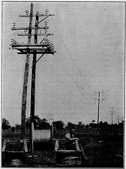
The line experimented upon at Niagara had a total length of 2000 feet, although, generally, only half its length was used. It was supported upon wooden poles, spaced about 140 feet apart. At first, the line wires were supported upon insulators, but it was found that the loss over the insulators was so great and so variable that if any reliable results were to be obtained, it would be necessary to find some other way of supporting the line conductors. Finally, the line wires were suspended by means of paraffined cords attached to the necks of the insulators. As long as these cords were clean, the loss over them was negligible. As soon as they became dirty, they were replaced by clean cords. A portion of the line with the suspending cords is shown in Fig. 1. This line will hereafter be referred to as the "Experimental Line".
| |||
| Fig. 1 |
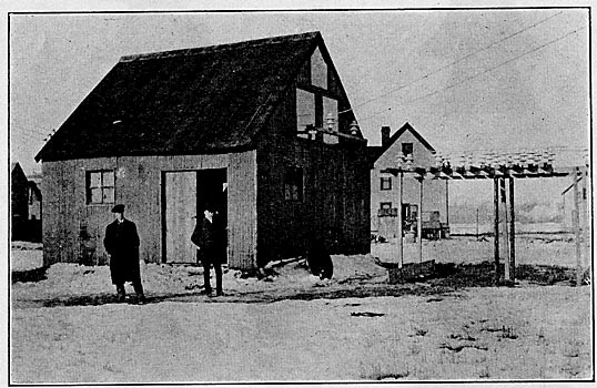
In addition to the experimental line, use was made of a number of cross-arms equipped with pins and insulators, similar to those used on the experimental line. This miniature line had a total length of only a few feet, so that the air loss between its conductors was negligible, the loss upon it being due to the insulators only. This miniature line will be designated hereafter as the "Dummy Line". It is shown in Fig. 2. The following conductors were used.
 |
| |||
| Fig. 2 |
The various types of insulators with which experiments were made are shown in Fig. 3 and will be referred to hereafter by the letters designating them in the illustration.
Two single-phase, 100,000-volt transformers were used, each having a capacity of 10 kilowatts. The endeavor was made to have the iron of these two transformers as nearly as possible identical as to loss, etc., for reasons which will be apparent from the description of the method of measurement employed. The two transformers were immersed in oil in the same boiler iron tank. They were of the core type, and had ground shields between the high-tension and the low-tension windings. The windings had taps for connecting the transformers, when desired, for polyphase transformation. The transformers had a number of special low-voltage coils, the use of which is explained below.
 |
| Fig. 3 |
The power for the measurements was obtained from a surface-wound, single-phase alternator of the old 133-cycle type, belted to an induction motor and driven at about one-half speed. This machine gave very nearly a sine wave under almost all conditions. The intention was to run it at 60 cycles, but instead it was run usually at about 73 cycles.
The wattmeter made use of was one especially constructed for this purpose. It is shown in Fig. 4. It consisted of the regular Weston wattmeter movement and shunt resistance enclosed in a suitable wooden box, and an external field coil which could be slid over the wattmeter movement or away from it, so as to give an instrument of considerable range. The field coil was enclosed in a suitable wooden frame. This field coil consisted of two identical windings, the wires being wound side by side, so that the magnetic axes of the two windings would as nearly as possible coincide. In addition there was supplied with the wattmeter an extra field coil exactly like the one used with the wattmeter. This extra field coil was used as an air transformer, as described later on.
The type of barometer, thermometer, and sling psychrometer recommended by the United States Weather Bureau for the measurements of barometric pressure, temperature, and relative humidity, respectively, were made use of in observing the corresponding weather quantities.
In addition the various necessary voltmeters, ammeters, etc., as indicated in Fig. 5 were employed. One of the ammeters was used in the high-tension circuit. It was mounted on an insulator and its movement was shielded from electrostatic action by a tin-foil shield inside the case and attached to one terminal. In addition to the above apparatus, we had for a while, the use of an oscillograph. Voltage curves were obtained by connecting the oscillograph to the D test coil in place of the voltmeter of Fig. 5.
The apparatus was all housed in a cheap building of corrugated iron, the outside of which is shown in Fig. 2.
The method of measurement employed was that devised by me and used at Telluride. In it the iron-loss of one transformer is balanced against the iron-loss of both transformers in such a manner that no iron-loss reading appears on the wattmeter, with the result that the wattmeter records only the losses in the high-voltage circuit of the transformer feeding the line. By this method of measurement the only correction which it is necessary to make in the wattmeter reading is to subtract from such reading the I' R loss in the high-tension coil of the transformer feeding the line.
The diagram of connections is shown in Fig. 5. One of the transformers, designated as the "Power Transformer" is used to
* The investigation was undertaken for the joint interests of the Telluride Power Transmissions Company and the Westinghouse Electric and Manufacturing Company. Part of the matter of the report was embodied in a paper read at the Fifteenth General Meeting of the American Institute of Electrical Engineers, June 30, 1898, by Mr. Chas. F. Scott, entitled "High Voltage Power Transmission."
** See paper entitled "The Conductivity of the Atmosphere at High Voltages", read at the 184th meeting of the American Institute of Electrical Engineers, Feb. 26, 1904.
[not finished]