[Trade Journal]
Publication: The Journal of Electricity, Power and Gas
San Francisco, CA, United States
vol. 21, no. 16, p. 241-246, col. 1-2
In the early days of power transmission practice, glass insulators were more largely used than those of any other material. This was no doubt due to the fact that suitable types and sizes were more readily obtained in glass. No commercial factories for the exclusive manufacture of porcelain insulators had been established, and the few porcelain insulators which were manufactured were made in potteries devoted more to the manufacture of low voltage porcelain ware such as knobs, tubes, cleats, etc., and not calling for the highest grade of porcelain nor perfection in manufacture. Hence it was that a great deal of trouble developed in the early porcelain insulators, whereas at the voltages used upon power transmission lines, glass insulators gave fairly efficient service.
| |||
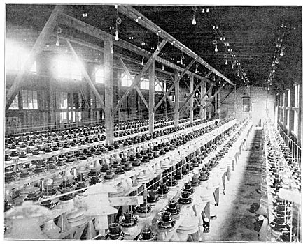
| Commercial Testing of High-Tension Insulators. |
At the period referred to (some twelve to fourteen years ago), the general commercial voltages were in the neighborhood of 20,000 volts, although there were some few instances of higher voltages in successful operation. At that time, glass insulators of the triple petticoat type from five and one-half to six inches in diameter were successfully used at 20,000 volts. This type was succeeded by glass insulators seven inches in diameter, which proved fairly serviceable at as high as 40,000 volts under suitable conditions. With one or two exceptions, the seven-inch diameter glass insulator has been the largest commercially manufactured and used. In the early development of the art, it was claimed that glass insulators possessed numerous advantages over porcelain. One of the principal advantages mentioned was that of being able to determine the existence of flaws or imperfections by visual inspection. High voltage testing apparatus had not been sufficiently introduced to make the universal testing of insulators practicable, and as it was considered that a porcelain insulator must be tested before use, their general use was discouraged.
As transmission lines began to increase in length and the demand for high voltages increased, it became necessary to enlarge the size of the insulators. It was soon found that there were decided limits to the size to which glass insulators could be extended; the reasons being inherent in the very nature of the glass itself, and its process of manufacture; that is, increasing the size of glass insulators necessitated the manufacture of masses of glass which could not be readily annealed, and even though annealed according to the best practice of the glass factories, extreme changes in temperature after erection on the poles set up strains within the glass due to expansion and contraction which often resulted in failures. This not only applies to the larger types of glass insulators but has been a frequent cause of trouble upon small glass insulators subjected to a wide variation in temperature.
Although the general practice has practically driven glass insulators from the field upon any new high voltage transmission work, yet the glass insulator still has its place and can be used successfully at moderate voltages; that is, up to 25,000 to 30,000 volts, under suitable climatic conditions, with success almost equal to porcelain. At the present time the only valid reason for using glass insulators in place of porcelain, seems to be the question of initial cost. Generally speaking, the average price of glass insulators should not be over fifty per cent of that of porcelain of the same general type.
Turning now to the question of porcelain insulators, it would appear that an engineer to properly design a high tension insulator should first be conversant in a general way with the process of manufacture in order to know the limits of shape, size, thickness, anal other problems of manufacture which of necessity influence the design of the commercial insulator. Therefore, a short description of the process of manufacture will probably not be out of order.
Porcelain for electrical purposes is a mixture of ground flint or silicon dioxide, and feldspar or potassium aluminum silicate, raised to a vitrifying temperature; that is, to a temperature sufficiently high to melt the feldspar, and from it unite the parts of flint into a perfect homogeneous body of uniform electrical and mechanical strength. The production of electrical porcelain differs from the ordinary pottery product in that in addition to presenting a symmetrical and flawless exterior it must possess inherent electrical and mechanical strength.
Though very finely ground and apparently in the last stage of subdivision, the clays after having been properly mixed as to quantity of each, are placed, together with sufficient water to form a liquid mass, in a ball mill or large iron tub lined with porcelain brick and half Idled with quartz pebbles selected from the glacial drifts of Iceland. The tub is caused to rotate on its supporting axle and the quartz pebbles still further reduce the clays in matter of fineness and thoroughness of mixture. From the ball mill, the mixture of clay and water is run through a lawn or 150-mesh screen to a cistern from which it is drawn by means of a power pump and forced into filter presses. Filter presses for this class of work are of the type used in many potteries, and consist of a series of cast iron rings separated by sheets of canvas pierced by a three-inch hole to admit the liquid clay. The canvas sheets so arranged form a series of pockets from which water may readily leak, but in which the clay is retainedthus forming "leaves" about thirty inches in diameter. As the pockets become filled with clay, the pressure steadily rises until no more can, with safety, be applied. The clay is then ready for working, but to ensure its being homogeneous and thoroughly pliable it is put through a pug mill or large sausage machine, which forces it through a die under pressure from whence it emerges as a long "sausage" about four inches in diameter. In this state it is delivered to the potter, who is thus furnished with a perfectly pliable and reliable clay upon which to work.
The process of drying and firing of electrical porcelain causes it to shrink about fifteen per cent, and accordingly the model of the insulator from which all moulds are made is fifteen per cent larger than the finished piece of ware. Such models are usually turned from blocks of plaster of paris, their surfaces oiled, and the moulds cast from them in one, two or three parts as occasion may require.
Having been properly dried, the moulds are filled with just enough clay by the potter's assistant, and are placed by the potter upon his wheel where the operation of shaping the inner side of the particular piece under consideration is carried on by the aid of the hands and a properly shaped former, which is held in place mechanically, and thus produces a perfectly uniform shape inside. The outside of course is determined by the shape of the mould. The mould with its clay is now set aside for some hours, during which time the plaster performs its functions of absorbing the water of the clay immediately adjacent to it. The clay has now become dry enough to handle, and is removed from the mould and carried to the finisher, who, by means of a revolving table, sets the partially dry ware to rotating, a wet sponge, and if necessary, a sharp knife being used to remove any irregularities and produce a smooth exterior. The piece thus finished is now set away and allowed to dry completely, after which it is clipped in a silicate solution, some of which is absorbed in the ware, thus forming a thin glaze or glasslike surface, whose only function is to produce a smooth finish as well as impart color to the insulator. At present a dark brown color is usually employed because of its supposed inconspicuousness compared to white; however, it is possible to produce any desired color by placing in the glaze the proper coloring matter.
In some of the smaller sized insulators the glaze accomplishes a double purpose, for besides covering the surface of the ware, it is made to serve as a cement for fastening the parts together, forming a neat and strong joint, for the glaze liquefies at the temperature at which the body vitrifies.
The kilns in which the ware thus prepared is fired are cylindrical, being about eighteen feet in diameter and sixteen feet high, lined with firebrick, and arranged with fire bags around the base, the fire from which is drawn over into the kiln and down through the floor and thence to the chimney. In order to protect the insulators during firing, they are placed in fire-clay receptacles called "saggers," which are piled one on the other until the inside of the kiln is completely filled, after which the entrance to the kiln is bricked up and sealed with fire-clay mortar. There remains now but to gradually raise the temperature to the required degree, which point is made evident by the fusing of small porcelain cones placed at regular intervals about the, kiln, an opening being left so that ready access may be had to them. Before each opening are placed four cones which fuse at various heats, and in firing a kiln, the temperature is raised until three of each set of cones are fused and the fourth very nearly so. In watching the cones the heat is so intense that a man cannot face it unprotected, and the light is so dazzling that a colored hand-glass is necessary to soften it so that the eyes can endure it. The heat is raised with such regularity that no unnecessary strains are created in the ware by sudden variations in temperature. The heat within some parts of the kiln is so intense as to fuse the firebrick with which the sides are lined. The proper heat having been attained, the fires are allowed to cool down and the annealing process carried on until an insulator absolutely free from internal strains is assured. The door is broken down and the finished insulators pass from the ceramic to the electrical test and shipping departments.
It has been found that the economical limit of size in a single piece of porcelain is about fifteen to sixteen inches in diameter, although larger pieces have been manufactured; notably the 75,000-volt insulators of the Kern line of the Edison Electric Company, which have a top diameter of eighteen inches.
The nature of the process of manufacture puts a decided limit upon the shape and size of the various parts of a porcelain insulator, and owing to the difficulties in burning, to say nothing of the expense entailed, all pieces of a large diameter, and at the same time of any considerable height, should be avoided. It is also well known that owing to the difficulties encountered in burning, all sharp angles should be avoided, and further, that each piece of ware should have a uniform thickness in all its parts, for the reason that if there is any considerable variation, the evaporation will be more rapid in the thin portions and cracks will be developed in drying, which will be aggravated in the burning.
It was formerly believed that the glaze upon the exterior of the porcelain insulator possessed greater insulating qualities than the body of the insulator. This idea no doubt became prevalent, due to the fact that the early porcelain insulators were made of inferior material, and oftentimes the porcelain was more or less porous. The glaze performed the function of filling up the pores and forming a glass-like surface of high dielectric strength, at the same time keeping the porcelain from absorbing moisture and becoming clogged with small particles of foreign matter which would eventually serve as a pathway for current leakage.
At the present time, the porcelain body of high tension insulators does not depend upon the glaze as an insulating medium as the porcelain itself, while clean, will stand the same test potential as with the glaze. The glaze, however, performs the important function of smoothing over the natural imperfections of the body of the porcelain and preventing the collection of foreign matter which would serve as a leakage path.
Glazes are of two types, namely, soft and hard. The soft glaze is merely a soft lead glass with sufficient clay present to prevent its settling until placed on the ware. Such a glaze is naturally very unreliable, not only because of the tendency of lead to volatilize under heat, but owing to its glassy nature, it is not able to expand and contract equally with the body of the ware, and the result is crazing. By "crazing" is meant that cracked condition of the glaze so commonly noted in art and table ware, and caused by sudden variations in temperature, making the mass expand or contract. Soft glazes being a species of glass, their power of expansion is not equal to that of the body to which they are attached; hence when a change in temperature occurs, the strain becomes too great for the brittle glaze, and breaks occur, leaving the glaze in small individual pieces on the surface of the ware. Crazing may not appear for some considerable time after the insulator is placed in service, but the elements will eventually cause this to occur.
Hard glazewhich-is the type used upon all high grade porcelain insulatorsis the true porcelain glaze, and its essential features are:
First. That it shall be composed of practically non-volatile substances (which excludes lead).
Second. That it shall contain only enough flux to fuse the matrix of silica and clay, and shall not flow or run.
Third. That the body shall be sufficiently absorbent when the glaze is applied so that the glaze may attack it and thus make a perfect union under the fire action.
Fourth. That the body and glaze shall have the same coefficient of expansion and shall mature at the same temperature.
It is much more difficult to produce a smooth and uniform surface where lead is not used, which may account for the wide difference in beauty of finish of insulators of different makes.
Any desired coloring can be obtained by the use of the proper colorants. The most generally accepted color at the present time is brown, although slate, or a neutral tint, has been extensively used. It is claimed that either brown or slate is much more inconspicuous upon the pole line than white, but no glaze which has vet been observed by the present writer has been found sufficiently inconspicuous to make its selection of any particular advantage in preventing damage to insulators by miscreants.
The matter of glazing joints does not usually come up for discussion in the consideration of insulators of the higher voltages, that is, 60,000 and over, but there is yet some considerable difference of opinion regarding glazed joints versus cemented joints for the moderate voltages, say from 25,000 to 35,000 volts. An insulator made with glazed joints, after having successfully passed the various mechanical and electrical tests, and having been placed upon the line in good condition, is undoubtedly as good an insulator as one made with cemented joints. When it is understood, however, that an insulator with glazed joints must be fired as one piece in the kiln, it will readily be seen that in the failure of any one piece, the entire insulator becomes worthless. This necessitates adding the loss of a higher percentage of parts to the factory cost, which the consumer is expected to pay. It will also be noted that unless a hard glaze is used in glazing the joints together, a loosening of the joints is liable to occur in the course of time, due to variation in temperature, for reasons above explained, namely, the different co-efficient of expansion of the porcelain and the glaze. The method of testing high voltage insulators is so well known that a description will not be attempted here. Owing to the nature of the ware it is generally conceded that all high voltage porcelain must be tested by wet test according to one of the usual methods in order to determine if any flaws which are not perceptible to the eye exist. Many of the imperfections in the body of the porcelain ware are microscopic and others are entirely concealed by the glaze so that the electrical test is absolutely essential.
In general, the electrical test applied to the various parts of multi-part insulators is kept very near to the arcing-over point, but there are limits to this test as described later. The number of failures under test is usually from two per cent to three per cent of the number tested. Once punctured, the porcelain is ruined and can by no known means be recovered.
The parts of multi-part insulators are united by means of pure Portland cement mixed with water only. After the cement has obtained the initial set, the insulators are subjected to an assembled electrical test of double line potential for a period of time sufficient to remove all doubt as to the electrical strength of the insulators, usually from one to five minutes.
Design of High Voltage Insulators.
Insulators for the lower voltages call merely for the introduction of sufficient good material between line and supporting structure to prevent destructive leakage. For voltages up to 20,000 little or no difficulty is experienced in securing such insulation, but above that voltage it becomes not only necessary to have good material in plenty, but it must he properly distributed in order that danger of puncture and severe leakage he reduced to a minimum.
The manufacture of good porcelain from a mechanical standpoint forbids that it be made so vitreous as to resist a puncture test of 65,000 to 70,000 volts through 1/2-inch or 5/8-inch thickness. It is useless to attempt to gain greater dielectric strength by increased thickness since individual cracks in thick pieces really reduces the effective strength to that of 1/2-inch or 5/8-inch porcelain. Accordingly it has come to be recognized as best practice to make no attempt to manufacture high voltage insulators in a single piece, but rather to secure greater electrical strength by multiplicity of parts. Though entirely possible to construct 30,000 volt insulators of one piece, and still apply a double potential test, experience has demonstrated that a multi-part insulator is much less liable to fail entirely when struck by stones or bullets than large single-piece insulators, and so prevents complete shut clown of the transmission line. There are many instances on record in which transmission lines have operated at long periods with the various petticoats of some of the insulators broken entirely away, leaving only enough of the insulator for mechanical support to the wire.
For the reason that greater safety from breakage, either mischievous or otherwise, is gained, as well as for greater normal safety factor, engineers are selecting multipart insulators at higher cost even for the lower voltages. In general, two-piece insulators are used for from 10,000 to 30,000 volts; three-piece for from 30,000 to 50,000 volts and four-piece for 50,000 to 75,000 volt lines now in operation.
Above 75,000 volts, the under-hung or suspension insulator works out more economically, and for entirely different reasons five to ten shells of porcelain are introduced.
Considerations of puncture strengths are the first concern of the designer. As before noted, good electrical and mechanical porcelain should be made of not more than 5/8-inch thickness with an ultimate electrical strength of not more than 70,000 volts. To give greater electrical strength, it is necessary to introduce other shells which continue to acid a proportional dielectric strength up to about 220,000 volts, at which point the curve gradually tends to become flat, and becomes very nearly so at 300,000 volts. With this to start with it is a very simple matter to provide insulators for any voltage up to the point where difficulties of manufacture begin to interfere with progress.
The 10,000 and 20,000 volt insulators have little to do with puncture strength, provided of course that the porcelain is of good quality, and so the question reduces to the form of necessary leakage distance and carrying capacity when subjected to an artificial rain approximating the worst conditions to which the insulator will be subjected. This is not so simple as appears on the surface, for while an insulator may behave admirably under a downpour of unprecedented intensity, Nature cannot be expected to limit herself to a vertical, or what is technically known as a 45 deg. rain, and moreover the precipitation is very likely to continue for a considerable time and be accompanied with sufficient wind to blow the rain very nearly horizontally.
It can be expected that after the first half hour of precipitation the inside of the innermost shell will have become thoroughly wet and the surface leakage comes into play. As is well known the persistence of any arc of definite length has to do with the voltage impressed and the current flowing and the failure of an insulator is of course amenable to the laws which govern arcs. A designer should assume that his insulator will sometimes become wet all over and should provide sufficient leakage resistance to prevent any considerable amount of current flowing, a small amount merely tending to dry off the insulator, whereas a large amount would most likely start a disastrous arc under the shells and would completely destroy them by its heat before extinguishing itself. Such an insulator represents very nearly the ideal, and it is to be regretted that so few lines are equipped with insulators of so great a margin of safety. It is usually true that only once or twice a year are insulators called upon to perform extreme duty. In fact, the insulators of most lines are for the greater part of the time working. very inefficiently, probably at not over 20 per cent of their rated capacity.
The next best thing is to provide as much dry surface as possible under average storm conditions, and to this end it is of value to note the progressive wetting of an insulator under rain. It is customary to mount the insulator well above the cross-arm, so that all of its shells are far removed from water spattering up from the arm. Assume an insulator of conventional design of three or four shells; the top becomes dripping wet at once, and the film of water held on the surface carries line potential to the outer edge. A certain amount of rain gets by the top and strikes upon the lower shells; part spattering upward and part downward, depending upon the angularity of precipitation. That portion which spatters upward soon wets the entire under surface of the shells above, and in this manner the potential is carried down to the lowest projecting shell. At this point the leakage path is broken, due to the fact that beneath the lowest shell there is no surface from which spattering may occur, and consequently it remains, and under this condition the central shell of the insulator is carrying the total strain, both as to puncture strain and against flash-over.
It therefore frequently happens that there is but one effective shell of porcelain interposed between the current which is leaking over the various portions of the insulator and the supporting pin. It has been pointed out that one thickness of porcelain should not be called upon to stand a puncture test of more than 60,000 volts. It will therefore appear that there may be cases in actual practice where the innermost shell of an insulator may be called upon to withstand this extreme voltage; hence the necessity for a well-designed and well-protected innermost shell, or center, as it is commercially called. The various shells must of course remain wet until the storm is over or some drying action is introduced. If the gap between the edge of the lowest shell and the pin is small enough, a small arc will be established, thus completing the circuit and permitting a leakage current, formerly held in check by the dry inner surface of the shell, to flow, though limited in volume by the relatively high resistance of the pure water film covering the insulator. This leakage current heats and vaporizes the water film; its first action naturally being where the current density is greatest at the neck of each shell, where fortunately the surface is not subjected to the direct force of the rain. Since potential is in no way concerned with resistance, the thinnest and consequently highest resistance film of water is sufficient to inaugurate the drying process, so that an insulator in service, if properly designed, will readily take care of itself.
From the foregoing, it will be seen that the dielectric strength of the inner shell of any multipart insulator and the distance between its lowest edge and the supporting pin are of utmost importance; the remainder of the insulator serving as a little more than a. resistance in series, or leakage distance, to limit the amount of current which may flow when arcing takes place. What has been said applies to insulators as it is necessary to build them to meet mechanical conditions imposed, and it is the mechanical characteristicsnot the electricalwhich influence their cost. Were it possible to make a porcelain wire of great strength, an insulator of perfect certainty of action could be produced at minimum cost. An insulator should not he regarded as an absolute barrier to current, but rather as a high resistance path between line and earth, and its design should aim to serve this purpose.
There has been considerable discussion with regard to the proper shape of the outer shells composing a multipart insulator; some engineers advocating concave; others, convex; and others, straight shells. There seem to be excellent reasons in support of all three shapes and an adjustment between the desirable points of the three calls for fine discrimination. The shape of the outer shells has a direct influence upon the amount of spattering of rain-water upon the under surfaces of the remaining petticoats. The convex shell will probably keep dry the longest, since a large portion of the falling water is de-gained between the various shells by the use of the concave fleeted away. On the other hand, much greater clearance is shape.
The foregoing applies equally well to low-voltage insulators, though up to 40,000 volts it is hardly necessary to provide protection for the innermost exposed shell, since its own strength is entirely ample.
So much space has been given to the discussion of the value of the insulator when under rain that its pleasant weather qualities may seem to have been overlooked, but there are sudden and severe demands upon an insulator in pleasant weather, mainly from lightning and switching. When a rise of potential far above normal working voltage comes upon a perfectly dry insulator, the stress between line wire and pin is very sensibly increased, and that this stress shall not be too severe, the distance between line wire and pin should be made ample by the introduction of several shells of porcelain. The specific inductive capacity of porcelain, or its flux-carrying capacity, is a perfectly definite thing, compared to air about 4.4, so that for any given potential, area of contact, and thickness of shell, the density is determined. Porcelain, however, unlike some dielectrics, gives due notice, when overburdened, by a pale violet light over its entire surface.
Mechanically insulators can be designed for any load by the proper disposition of material. Good electrical porcelain has a crushing strength in excess of 15,000 pounds and tensile strength ranging between 1,500 and 2,000 pounds per square inch.
One of the worst conditions which Pacific Coast engineers have been called upon to contend with is the heavy sea fogs, immediately adjacent to the coast. These fogs are particularly troublesome when they occur during the summer months, or before the rains have had an opportunity to clean the summer's accumulation of dust and other foreign matter from the surfaces of the insulator. Under fog conditions, as stated above, it has been found necessary to greatly increase the creeping distance from line wire to pin. As stated in the early part of this paper, there are decided limits to the commercial size of a piece of electrical porcelain. Added creeping distance has been very ingeniously introduced, without increasing the outside dimensions, by means of corrugations. To be of the greatest service, these corrugations should be wide and deep, to prevent insects and foreign matter from filling them up and reducing the surface to the same (or lesser) value as a plain surface.
The latest development in exceedingly high-voltage insulators is a reversion to a type long since discarded by lower-voltage engineers; that is, the underhung or suspended type of insulators. The first English telegraph systems were insulated by underhung insulators of bowl-shaped porcelain, and, to come down to the present time, our trolley wires are suspended below a supporting device.
| |||
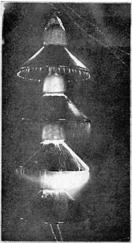
| Insulators in Five Minute Rain Just Previous to Failure at 200,000 Volts. |
The reason for using suspended insulators is largely a matter of cost, since it is entirely possible to build porcelain insulators of the conventional type of sufficient size to successfully operate at any voltage, but the extreme height and diameter of a pin-type insulator for 100,000 or 150,000 volts make the cost prohibitive. A suspended type of insulator has several advantages which it is well to understand before going into details of design. Of paramount importance is the unit formation, making it possible to increase the effective insulation whenever it is desired to raise the line voltage or wherever it seems desirable to present extra leakage surface because of salt fogs smoke from railways and factories, or other adverse conditions. Many lines start operation at much lower potential than designed for, because the initial load is light and the potential need be increased only when regulation demands it. With the pin type of insulator there is no alternative but to invest at the start in the largest insulators which the line will ever need, whereas, in the suspended form, additional units may be introduced whenever the growth of power business warrants an increase in potential. In the pin type of insulator the nearness of line wire and pin must always prove a weak point for lightning assault as well as an aggravator of line-charging current difficulties. The suspended type gets away from both difficulties by a wide separation of line conductor and supporting structure. Incidentally the position of the conductor below the cross-arm permits the supporting structure to act as a lightning rod, and so to relieve the line of much lightning stress.
Mechanically, provision must be made to prevent the swinging conductor from coining too near the tower structure, but the extra length of cross-arm necessitated by this feature is more than compensated for in cost by the fact that there are no twisting strains upon the arm.
Insulator unit formation presents another very positive advantage in the matter of breakage. When a shell of a pin-type insulator becomes cracked or broken, the whole device is rendered worthless, as it is utterly impossible to break the cement joint forming the bond between shells. Further, the cracking of a shell, especially an inner shell may cause immediate shut-down or at least shut-down during the first severe rain storm. On the contrary, the breaking or cracking of one of the shells of a suspended unit-type insulator takes away but that one unit from the series; thus, in the case of a 5-unit, 100,000-volt insulator, a broken unit reduces the total strength but 20 per cent.
With these very evident advantages, it is small wonder that, with voltages reaching toward 100,000, the underhung insulator should be adopted. The first question, that of mechanical strength, was promptly disposed of by so designing porcelain parts that strains were all compression. The next question, that of electrical strength under normal operating conditions, was not so easily solved. In the first designs, single shells of porcelain of 5/8-inch thickness were used, but when a series of 5 such shells was subjected to a 300,000-volt test, a new condition was found to have been introduced in the way of a potential rise around the first units, and it was found by repeated test that any sudden application of potential, or even change in potential already applied, would puncture the end shells, which, if made of economical pottery size, i. e., 14 inches diameter, would have a flash-over potential of approximately the ultimate puncture strength. This condition analyzes somewhat as follows: The shells and metallic connecting links form a condenser of certain definite capacity, which for the sake of analogy may be likened to a mass of rubber or other elastic material. Carrying out the analogy, the rubber is struck a smart blow with a hammer. The surface struck and layers of material immediately adjacent to it, feel the force of the blow most severely, and if the mass be thick and of great inertia, the force of the blow is barely perceptible on the surface opposite to that where the blow was struck. Moreover, the elastic material is no sooner struck and compressed than it attempts to return to its normal shape. This property of inertia is duplicated in the action of condensers in series; call it what you wish, dielectric hysteresis, or anything else, the effect is there, and if proper precautions arc not taken, the outer layer of resisting medium, in this case a porcelain shell, will be disrupted. Unquestionably the dielectric strength of the unit must be increased, and the proper method is by supplying an inner protecting shell, so that the puncture strength of the built-up unit shall be far in excess of its flash-over potential. A unit so constructed is practically indestructible, and will carry continuously its flash-over potential without heating or its surface being covered with static; which impairs the efficiency by shortening the leakage path. Under normal operating conditions the end unit is the only one which is subject to unusual strains, but the failure, either by mechanical breakage or arcing over, may at any time put similar strain upon other units, so it is a wise provision to guard all shells against possible puncture. Having made the unit secure against puncture, the next concern is with leakage distance, which must be made of sufficient length to prevent any considerable current flow when the entire surface is covered with a thin film of water. Here again cost governs, since the unit construction permits the use of a few large or several small parts. As noted before, 14 inches is an economical size for the potter to produce, and, as the metal parts are the same for any diameter of shell, it is this size which returns most in insulation for each dollar invested. The shape of the shells is not of importance, since in testing to flash-over under working conditions pains were taken to wet all surfaces thoroughly and so produce artificially the worst possible conditions; but it must not be taken for granted that leakage over an insulator is a desirable thing; in fact, the time when an insulator will leak sufficiently to dry itself should be postponed as long as possible by logical designing. To accomplish this it is of course necessary to permit as little water as possible to spatter on the under side of the shells, and this is best effected by deflecting the water away rather than toward the insulator. If this were the only thing to consider, the best shape of shell would still be in question. There are, however, other conditions. When, in the course of a severe storm, the under as well as the upper shell surfaces have become thoroughly wet and leakage has commenced, the first spot to become dry is the inside of the innermost shell at the point of smallest cross-section, and a small arc is at once formed, which, if allowed to persist, will heat and crack the shell. To avoid this, the edge of the shell is brought down till the lower edge of the outer petticoat is of such a distance as to induce the arc to play between it and the malleable iron cap of the unit immediately below.
An arc of considerable magnitude may be maintained between these two points without heating the shells above sufficiently to cause cracking, since the air currents established tend to keep down the temperature. Current sufficient to support such an arc will, unless the rain he very heavy indeed, dry a portion of the upper surface of the shell, which causes the arc to straighten out, and if there be sufficient current at high voltage, it will eventually be held between the conductor and the supporting structure. There is thus a progressive breaking down between the beginning of actual leakage and the maximum arc, which is not sufficiently close to the insulator to damage it: With only 500 kilowatts at 300,000 volts available, the above deductions were found to be true and the ability of the design to rid itself of arcs formed upon it demonstrated beyond question. The suspended insulator thus becomes an automatic relief valve, which may be relied upon to discharge the line safely and effectively without damage to itself or serious interruptions to the service.
The underhung system of insulation works out with pleasing directness and simplicity, and its comparative cheapness argues for its wide adoption for the higher voltages. The cost of such insulators, as at present manufactured, ranges from $1.60 to $2.00 per unit, depending on the nature of the fittings. At least two 14-inch units would he required for 60,000 volts, and as a good 60,000-volt insulator can be secured for prices ranging between $1.70 and $2.30 each, the question of the use of suspended units for voltages below 75,000 to 80,000 is largely one of safety factor and investment.
The foregoing has given little which could be used in the determination of the proper insulator to use for any particular voltage, and it is quite in point to add here that every case is special. Insulators well suited to one locality are out of reason, in safety factor provided, for use elsewhere. A single transmission line of less than 100 miles in length may easily pass from high, clear mountain air to foggy, dusty surroundings which are a constant menace to continuity of service. Again, the cost of complete immunity may well he balanced against cost of possible shut-downs, a point well illustrated in many present transmission lines in which branch lines arc equipped with much smaller and consequently cheaper insulators than those upon main lines.
It is not intended to convey the idea that every line should have a special insulator, but that the characteristics of the proposed line should be made known to the designer in order that all points may be well guarded against. It is quite likely the resulting recommendation will he upon an old established type of which all characteristics are known, and though its use for any specific case may not call into use all it is capable of, it will quite likely prove cheaper to produce a standard article of larger size than to make a special design of just sufficient capacity.
A forecast of the future of any business, though never safe, is always interesting.
Concerning the highest practicable voltage, without reference to anything but insulators, it is safe to say that insulators for the heaviest mechanical strains and for the highest electrical stresses can be manufactured at moderate cost, so that limitations of transmitting voltages must at the present time be looked for in other directions than in insulator design, porcelain insulator design in particular.
*Paper read at meeting. San Francisco Section of the American Institute of Electrical Engineers, Sept. 25, 1908. Much of the data in this paper is taken from an article on "High Voltage Insulator Manufacture" by W. T. Goddard.
