[Trade Journal]
Publication: Electrical World
New York, NY, United States
vol. 52, no. 20, p. 1061-1063, col. 1-2
Hydro-Electric Power Plant on the Piabanha River, Brazil.
ONE of the largest hydro-electric stations in South America has just been completed on the Piabanha River in Brazil. The plant is owned by Messrs. Guinle & Company, of Rio de Janeiro, and the energy is transmitted to Nictheroy, Petropolis, Rio de Janeiro and other cities in the State of Rio de Janeiro as well as to many industrial establishments along the lines. The present plant, which is known as the Nictheroy power plant, represents only a part of the entire power project, it being the intention to enlarge the plant to keep pace with the industrial development of the State; the ultimate rating being 50,000 hp. To generate this amount of electricity the company has acquired the right to the Piabanha, Fagundes and Parahybuna Falls. The Piabanha River rises in the Serra dos Orgaos and flows through an irregular and rocky valley as far as the town of Areal, where it is joined by the Rio Preto, a river having its source in the same watershed as the Piabanha. The reinforced stream plunges over a succession of more or less important falls and after being joined by the Fagundes empties into the Parahiba River near the town of Entre Rios. At first the company undertook to utilize the Fagundes River, which falls 130 m in a short course; but the concessions called for the completion of the work in a comparatively short time and in order to comply with the conditions exacted by the government the Piabanha River was utilized, there being sufficient hydraulic power for present requirements. The falls above and below the junction of the Piabanha and the Fagundes were secured, together with all the existing estates on both banks of the latter. Investigations show that within a radius of 1-1/2 miles 50,000 hp can be developed. On the Fagundes River, with a high fall and a comparatively small volume of water, the company intends to build a large storage reservoir. The fall now being utilized is the one formed by the Piabanha just before it joins the Fagundes above the Alberto Torres station of the Leopoldina Railway.
| |||
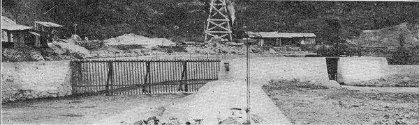
| Fig. 1 -- Dam and Intake. |
| |||
| Fig. 2 -- View of Pipe Line. |
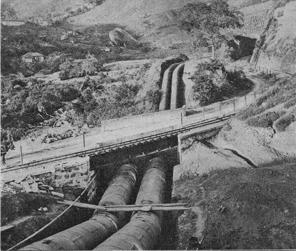
During the greater part of the year the river has an almost constant minimum discharge of 20 cu. m per second. During the rainy season the flow is equal to 700 cu. m per second. With this in view and also the fact that the river is flanked by both public and private properties, a dam was erected above the first fall. Running obliquely across the stream for about two-thirds of the way is a ledge of solid rock which projects above the water at minimum flow. The dam is built on this ledge and is 110 m long and 4 m high. Because of the damage that a higher dam would necessarily occasion in time of floods, the construction of such a dam was not undertaken. The dam, therefore, has an oblique direction across the river and joins the intake reservoir at the left. The latter is 15 ft wide by 25 m long and has walls 9 m high. Racks extend across the entrance to the reservoir and also across the supply pipe gates. For some little distance outside the supply gates the floor of the intake reservoir is given a gentle slope so that at the gate! the distance between the bottom of the reservoir and the bottom of the gates is i m. This incline serves as a sand trap. A gate is inserted in the wall of the dam just above the supply- pipe gates to get rid of accumulations. An air chamber is placed in the pipe line just beyond the gates to guard against collapse due to the sudden stoppage of water. Four lines of pipe will lead from the intake reservoir to the head reservoir. Two lines are at present installed and these are 1.8 m in diameter and have a total length of 2200 m. The pipe lines rest on either bed rock or concrete sleepers. Where the pipe lines cross below railway lines and public highways, bridges are erected, of steel in the former case and of reinforced concrete in the latter case. The intake reservoir is built of granite, which abounds in the district and is cheaper than cement. Fig. 1 shows the intake reservoir and Fig. 2 is a view of the pipe line showing a railway bridge and roadway built over it. The pipe lines run exposed their entire length.
| |||
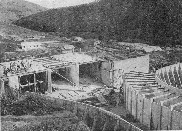
| Fig. 3 -- Canal Leading to Penstocks and Spillway. |
| |||
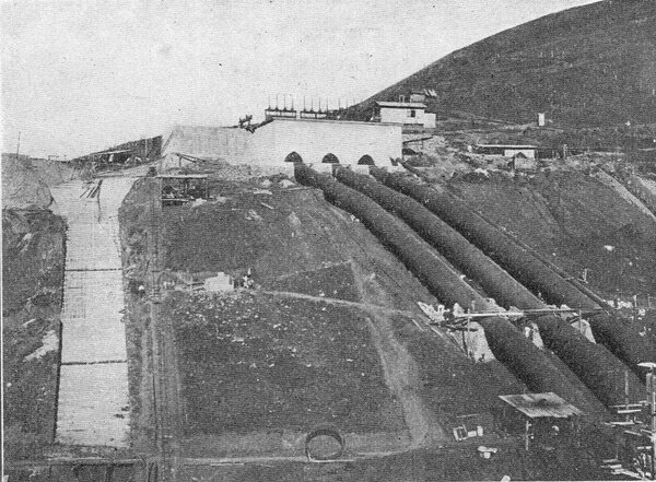
| Fig. 4 -- Penstocks, Spillway and Reservoir. |
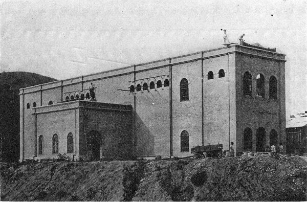
The head reservoir. Fig. 3, consists in the part following the pipe lines of an open canal of reinforced concrete 50 m long, 7 m wide, with walls 5 m high. At 50 m from the wall through which the pipe lines enter the reservoir, the canal begins to widen by degrees until it reaches the gates from the penstocks, where it has a width of 20 m. To one side of the reservoir is a spillway over which the water falls into a canal, whence it is conveyed to a tailrace 300 m long. The tailrace is an open canal of masonry and carries the water back to the Fiabanha River. A view of the race is shown in Fig. 7. The head reservoir floor has an average thickness of 20 cm made up of a mixture of one part cement, four parts sand and seven parts stone. This is topped with a 3-cm mixture of one part cement and two parts sand. The reinforcement varies in thickness from horizontal rods at the top to 1/4-in. rods at the bottom, the spacing varying from 20 cm at the top to 3 cm at the bottom. The vertical rods are 1/4 in. The concrete mixture used on this latticed reinforcement was composed of one part cement, two parts sand and three parts stone. The walls are 5 cm thick and are buttressed at intervals with reinforced concrete buttresses 5 cm thick, 5 m high and tapering from the bottom, where the footing is 2.3 m long to the top, which is flush with the wall. A sand trap is provided in the head reservoir with a gate into the spillway, and the floor of the reservoir is curved downward near the outer wall to the main penstock, the latter connected about 2 m below the floor at the outer wall. The exciter penstock enters about 1 m above the floor of the reservoir.
| |||
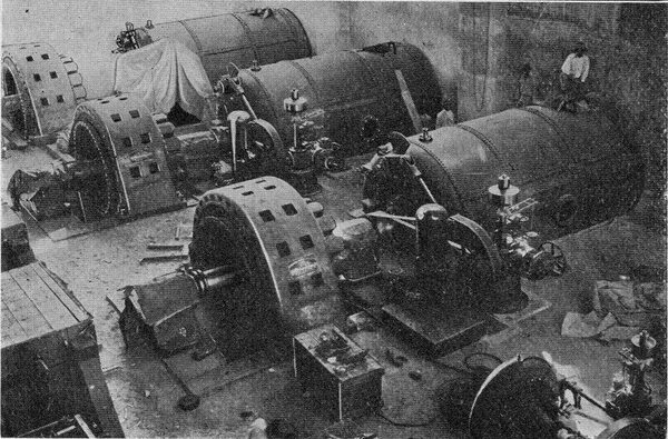
| Fig. 5 -- Interior of Generating Station at Alberto Torres. |
| |||
| Fig. 6 -- Oil Switches and Lightning Arresters in Generating Station. |
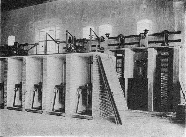
Four penstocks lead from the reservoir to the power house. Three of the penstocks are 2.8 m in diameter and 105 m long, and the fourth is 70 cm in diameter. The large penstocks are for the main water turbines and the small penstock is for the exciter turbines. Each penstock rests on a separate pillar, as shown in Fig. 4, and is equipped with a relief valve and air valve. The penstocks are built of steel and the net head at the turbines is 57 m. The generating station is built of brick and masonry with concrete floors. The equipment comprises three horizontal-type Francis turbines rated at 5150 hp and built by J. M. Voith, of Germany. These are direct-connected to three 3000-kw, 2300- volt, 60-cycle, three-phase General Electric alternators. The exciters are rated at 75 kw, 226 volts, and are driven by two 130-hp turbines, to which they are direct connected. Two Tirrill regulators are used in connection with the exciters for keeping the voltage constant. Each of the turbines is equipped with a waterwheel governor. of German make, as shown in Fig. 5, which is a view of the interior of the station while the equipment was being installed. The main switchboard is in a gallery overlooking the generator room. The switchboard is of the bench-board type and all the switches and field rheostats for the generators and exciters are electrically operated, the energy for this purpose being supplied from a storage battery of 55 chloride accumulator cells. The voltage is raised from 2300 to 44,000 by means of nine oil- and water-cooled transformers, each of which is rated at l000 kw. The high-tension circuits are controlled by motor-operated switches and are protected by multi-gap lightning arresters in the station and by horn arresters on the lines.
| |||
| Fig. 7 -- View of Generating Station, Showing Tail Race. |
| |||
| Fig. 8 -- Switching Station at Cascatinha. |
| |||
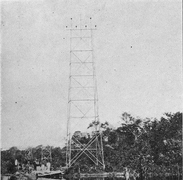
| Fig. 9 -- Transmission Line Tower at Guapy Canal. |
The transmission line is about 50 miles long, and because of the extreme dampness in the region through which it passes, a higher tension than 44.000 volts was not attempted. The line runs near the sea for a great part of its length, following the contour of the Bay of Rio de Janeiro and also passing through some extensive swamps en route. The transmission line is made up of two three-phase lines of copper, each of which is designed to transmit 5250 kw.
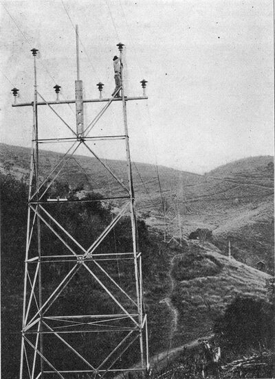
The line is supported on 50-ft. galvanized steel towers throughout, there being 600 towers placed about 200 m apart. A galvanized steel stranded cable runs along the top of the towers and is thoroughly grounded as a protection against lightning. A telephone line is also carried on the towers. The wire for the transmission circuits was supplied by John A. Roeblings Sons Company, the towers and pipes by the Riter- Conley Company, and the insulators by R. Thomas & Sons.
| |||
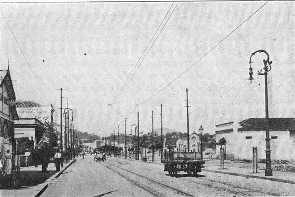
| Fig. 10 -- Ornate Arc Lamp Posts in Nictheroy. |
| |||
| Fig. 11 -- General View of Transmission Line Tower. |
Where the lines cross midway the Guapy Canal, which is navigable, they are elevated so as not to interfere with shipping by means of two 30 m towers, one of which is shown in Fig. 9. The transmission line for the most part runs in a comparatively straight line, although over very mountainous country, from the generating station to the switching station. For about four months of the year the rains and thunderstorms in the territory covered are quite heavy.
At Cascatinha, about 30 km from the generating station, the switching station shown in Fig. 8 is located. This station contains all the necessary switchboard and lightning arrester equipment for controlling the two incoming and six outgoing lines which converge at this point. From this station two lines run to Nictheroy, across the bay from Rio de Janeiro, and about 60 km from Cascatinha; two lines to Petropolis, about 6 km from the switching station, and two lines will run to Rio de Janeiro. The distribution lines to Petropolis have a tension of 6600 volts, while the lines to Nictheroy have a tension of 44.000 volts. The lines to Rio de Janeiro will have a tension of 100,000 volts.
A substation equipped with four 175-kw, step-down transformers and necessary equipment for receiving energy and distributing it to the industries in the zone is located at Mage City. Similar equipment is housed in the switching station at Cascatinha for supplying the City of Petropolis. The substation at Nictheroy is equipped with step-down transformers rated at 750 kw and the usual switching equipment for supplying energy for lamps and motors to the city, which is the capital of the State of Rio de Janeiro. The substation which will shortly be erected in Rio de Janeiro will be the largest of all. Contracts have been signed with the Central Railroad of Brazil, which contemplates equipping its lines around Rio de Janeiro with electricity as a motive power. The city of Nictheroy is lighted with enclosed arc lamps, as shown by Fig. 10, and the company also supplies electrical energy for lamps and motors.
