[Trade Journal]
Publication: The Journal of Electricity, Power and Gas
San Francisco, CA, United States
vol. 21, no. 22, p. 345-369, col. 1-2
THE SAN JOAQUIN VALLEY
What Electricity Is Doing For This Region Under the Direction of the San Joaquin Light and Power Company
By Clem A. Copeland
Introductory
The land of California is a constant source of pleasant surprises. The proud Native Son as well as the tenderest footed stranger meet on a common ground in California, where a new land is being revealed to both alike. From the weird waste of the valley of the Salton Sink, 287 feet below sea, scarcely 90 miles distant, to the barren crags of Mount Whitney, 15,000 feet in height, there is always something new under the sun. From the pranks of Burbank, with the luscious spineless cactus on the surface, to the 4,455-foot oil well below the surface there is food for man and beast, and food for serious thought. A State is worthwhile when it produces 50,000,000 barrels of crude oil a year, thus outdistancing all competitors. Other statistics of too bulky a nature would be a source of pleasure and silent surprise to the one who thinks he knows, but doesn't.
| |||
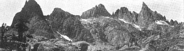
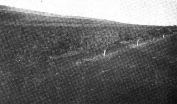
| Fig. 1 Backbone of the High Sierras, July Snows and Lakes at the Source of the San Joaquin |
The great, generous valley of the Sacramento and San Joaquin, fifty miles wide, with its 23,000 square miles of fertile, level floor from Redding to field, equivalent in area to New Hampshire, Vermont and Massachusetts, will ere long produce a good sized nations supply of many products of the farm.
As a sample, we may select a small patch around Fresno, the commercial center of the San Joaquin Valley, covered by the system of the San Joaquin Light and Power Company. This comparatively small section, composed of portions of four counties, produced over $41,000,000 worth of necessities the last fiscal year. This amount is derived from raisins, wine, brandies, green, dried and canned fruits; from cereals, hay, live stock and dairy products; from timber and its derived industries; from petroleum and its derivatives; from citrus fruits; and from minerals and clay and the products thereof. The present year will show a marked increase over the figures of previous years.
The newest industry of this section is the propagation of the Smyrna fig, until quite recently a failure. Last year, however, the packing houses around Fresno shipped 6,400,000 pounds of this fruit, due to improvements in pollen fertilization by the importation of the fig wasp from its native home with the Smyrna fig.
| |||
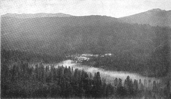
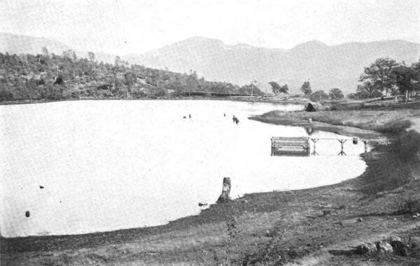
| Fig . 2 Crane Valley Reservoir and Mountains Forming the Watershed of the North and South Fork in the Upper Distance. |
Thus we find in this fertile district a potent excuse for the electrical development of water powers. Co-ordinate with this demand, there is found an abundance of water, if properly conserved, at exceptionally convenient localities for obtaining high heads, and where climatic conditions are also favorable to the economical generation and transmission of power.
Prosperous California husbandmen and manufacturers are keen and far sighted in resorting to hydroelectric power with an apparently unlimited appetite, notwithstanding the fact that within a stones throw of the great Kern and Coalinga fields, producing some 30,000,000 barrels per year, crude oil may be obtained for the generation of power at a price equivalent to the best coal at $2.00 per ton.
The system of the San Joaquin Light and Power Company, with its extreme simplicity and reliability, is illustrative of this discussion.
| |||
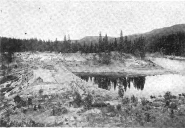
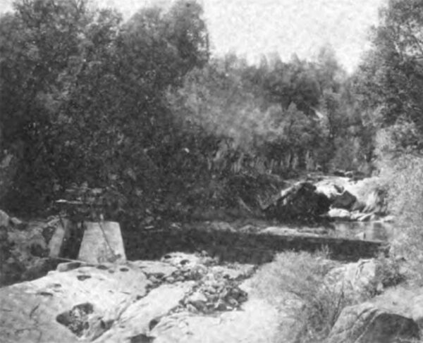
| Fig. 3 Crane Valley Dam |
| |||
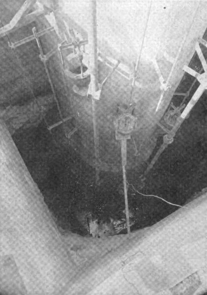
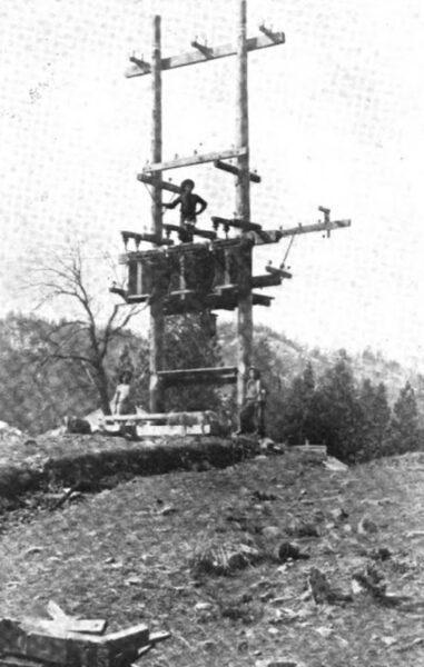
| Fig. 4 the New Gate Tower of the Crane Valley Reservoir |
If one could see this system, thus believing, he would travel twenty miles in the crisp morning air, from Fresno across the level floor of the valley to the rolling, oak-clad foothill zone of the Sierra Nevada, through the bull pine belt and further half way across the zone of the sugar pin and cedar, when, after fifty-six miles of travel horizontally, and nearly a mile vertically, one is introduced to the quiet evening camp, with the smell of the pine and the feel of a nice warm fire.
Crane Valley is discovered at sunrise, a peaceful contrast to the cares that infest ones city life.
Crane Valley Reservoir Head Works of Nos. 1, 2, 3 and 4
By the light of the morning sun, the views of Fig. 1 and 2 were obtained, though unfortunately the amber colors of the fall mosaics, set into the forests of pine, cannot be shown, nor the blue of the sky dipped into the deep, quiet waters of the lake.
| |||
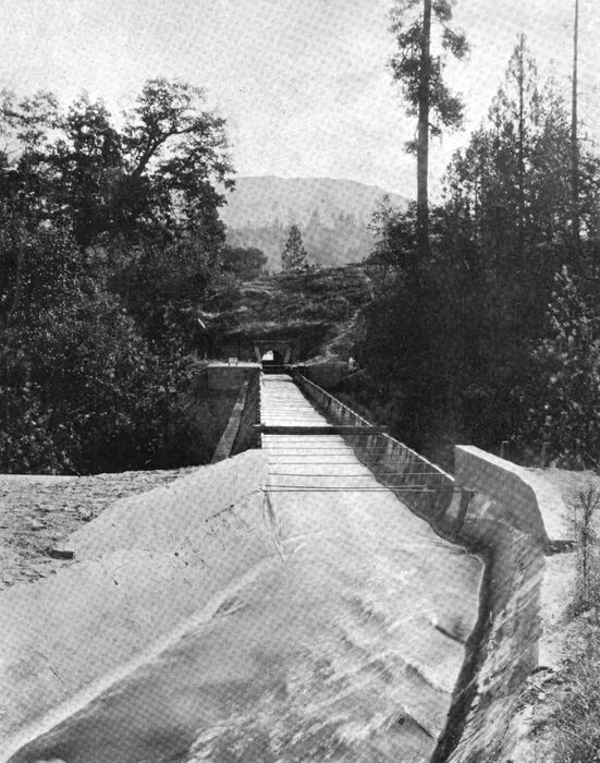
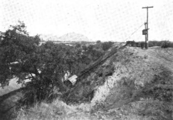
| Fig. 5 Ditch, Flume and Tunnel, No. 3 Conduit Line. Down the Canyon From the Crane Valley Dam, Beneath the Smoky Veil in the View in Fig. 2, the Conduit Extends for 4.22 Miles, A Part of Which is 5 Feet Wide at the Bottom, the Remainder Being 6 Feet in Width. the Ditch Thus Formed is in A Substantial Bed of Disintegrated Granite the Greater Part of Its Length and is Plastered With Cement." |
The dam here shown was constructed in the path of the North Fork of the San. Joaquin River where it widens out to form Crane Valley to conserve the winter waters, whereby they may be used in power house No. 3, again eventually in prospective plant No. 2, and finally in the old original plant of No. 1. Behind this dam of hydraulic construction is impounded 4,300 acre-feet of water during the wet months, to produce a sufficient flow for the present of No. 3 and No. 1 power houses, during the months of drouth, when added to the normal summer flow of the North Fork which empties into the lake two miles up stream.
Unexpected prosperity and enlargements of the system since this dam was built necessitate the construction of a new and larger one at this point. Viewing the photo of Fig. 3, at the extreme left edge, we see where this solid concrete structure will be cemented to the bedrock, fortunately on the surface at this point, just below and adjoining the present dam. The new lake thus formed will be 150 feet deep at the dam, and, due to the very level nature of the floor of Crane Valley, an extensive mountain meadow, the water will extend for five miles up Crane Valley, or up the valley of the North Fork, and will contain 68,000 acre-feet when filled. There will thus be conserved enough supplying a power-house capacity of 17,314 kilowatts delivered to the line, in the two present and one perspective power house below, when the South Fork water is emptied into the reservoir in the manner described in the notes on No. 4 power house.
The problem of letting the water out of a reservoir filled to a depth of 150 feet is no small problem. Anticipating the construction of this dam, there is being erected a gate tower at present 66 feet in height, or perhaps we should say deep, at the present time, which will eventually be extended to 151 feet in total height. To start this tower at the bottom of the present lake and near the dam, from the bottom of which the tower is being built. The peculiar view of Fig. 1 was taken looking down the pit on top of the lids of the various valves of different sizes located at different heights, thus admitting water at any desired level. The valve lids are connected with stems which will extend to the top of the tower, where their threaded ends will engage with a hand-wheel-nut for adjusting the opening of the valve. From the bottom of the inside of this concrete tower, 3 feet in thickness at the is point, a tunnel 720 feet long extends through flinty blue granite under the present and contemplated dams to a appoint well down stream on the ditch line. This is the second tower of this kind ever built, its predecessor being constructed to discharge water from the Arrowhead Reservoir Companys reservoir, now being filled to a depth of 250 feet, in the mountains near San Bernardino, California. When completed, this reservoir will be capable of supplying a power-house capacity in the three plants of more than 20,000 delivered horsepower.
Prospective Hydraulic Plant No. 4
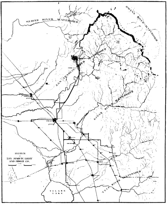
A study of the map II will show the contemplated power source of plant No. 4 to tap the waters of the South Fork of the North Fork, and by means of a very short conduit and pressure pipe a fall of 1,900 feet is to be obtained, the waters mingling with those of North Fork in the Crane Valley Reservoir, ready for the three power houses below Crane Valley.
Conduit of No. 3 Power House
Down the canyon from the Crane Valley dam, beneath the smoky veil in the view of Fig. 2, the conduit extends for 4.22 miles, a part of which is 5 feet wide at the bottom, the remainder being 6 feet in width, both parts being 3-1/2 feet in depth and trapezoidal in cross section, with 45-degree sides. The grade of the narrower section is 0.15 foot per 100 feet. The ditch thus formed is in a substantial bed of disintegrated granite the greater part of its length, and is plastered with cement. The capacity when running 3 feet full is 100 second-feet.
| |||
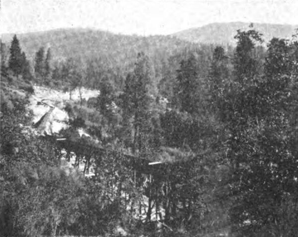
| Fig. 6 "Hitting the High Places" on No. 3 Conduit Line, Looking Up Toward Crane Valley. |
| |||
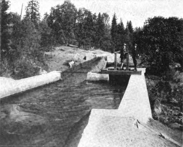
| Fig. 6a Sand Settling Box on No. 3 Conduit Line. |
There are four tunnels on this line, 5 feet wide and 6 feet in height, on a grade of 0.3 foot per 100 feet. The flumes, thirteen in number, are seen in Fig. 5 and 6 to consist of semi-circular steel of 3-foot radius, with a grade of 0.3 foot in 100. Some interesting trouble has been experienced in taking care of changes of temperature in the steel flume, which became great due to the large difference between the summer and winter and the night and day temperatures, co-ordinate with a small flow of water in the day time, when the temperature is high. Canvas expansion joints have been found a simple and inexpensive solution of the difficulty.
The unevenness of the country in this canyon may be appreciated from the fact that the tunnels and trestles comprise 27 per cent of the total length of the conduit, which thus just hits the high places on its way to the pressure pipe of No. 3 power house.
No. 3 Regulating Forebay Reservoir
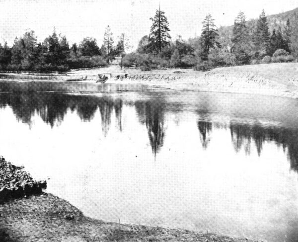
In the view of Fig. 7 is seen a lake of quite respectable proportions, above No. 3, containing 33 acre-feet or a four hours supply of 100 second-feet for regulating purposes and in case of accident on the conduit line. This type of reservoir performs an exceedingly useful office in California water powers, where small quantities of water are used under high heads. In the present case, as an instance, a uniform flow in the conduit line from the Crane Valley Reservoir is conserved in this regulating reservoir to accurately fit the conditions of load or any emergency overload over the lighting peak in the power house below, acting thus like a storage battery of 100 per cent efficiency, so that in conjunction with needle regulating nozzles there is absolutely no loss of water.
| |||
| Fig. 7 Regulating Forebay Reservoir for No. 3 Power House. |
It is readily seen that in an open-conduit line four miles long, with a limited forebay, the flow would necessarily have to be great enough to carry maximum load at all times and the economical feature of the needle regulating nozzle would be lost, by waste of water over the spillway.
In this connection a system of simple and effective design has been devised to indicate the height of water in the reservoir. A bank of lamps in the No. 3 power house, operated in conjunction with a float in the reservoir, is so connected that the lamp burning indicates the number of feet of water. As the water in the reservoir 3,000 feet away. As the water lowers, one after another of the lamps are lit upon passing the even foot mark.
No. 3 Pressure Pipe Line
The water from the regulating forebay reservoir, described above, is taken into the pressure pipe line through a tunnel 20 feet below the overflow grade line, the upper end of the pipe consisting of a taper fitting 20 feet in length, being under the full pressure of the depth of water in this reservoir. The taper fitting, 60 inches and 52 inches in diameter, of 3/16-inch steel, conducts the water through a gate into the 52-inch pipe line 3,131 feet in length to the power house 401 feet below. The pipe is of the uniform diameter of 52 inches and divided into sections and thicknesses as follows:
 |
Suitable valves for relief, in case of water hammer, are provided, the pipe being covered with 18 inches of earth, and provided with massive concrete anchors at proper .intervals along its length.
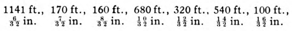
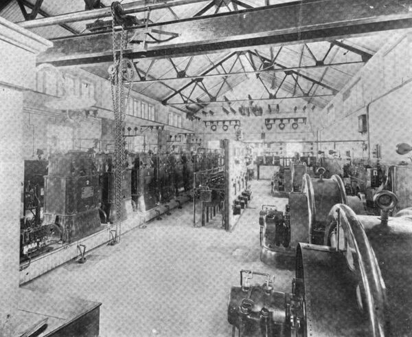
Power House No. 3
Without the introduction of a receiver, the water issues from the four 6-inch needle-regulating deflecting nozzles to impulse Power House wheels, two of which are connected No. 3 to each of the two 1,000-kw., 550-volt, 300 r. p. m., 60-cycle, 3-phase Bullock alternators, which feed solidly into the transmission line without protective devices, through non-automatic oil switches and disconnecting line switches. The generators are Y the neutral being grounded.
| |||
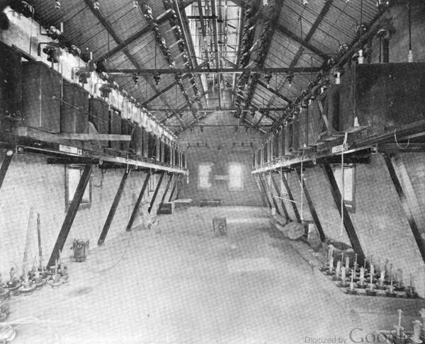
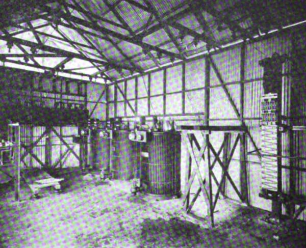
| Fig. 8 Interior of No. 3 Power House |
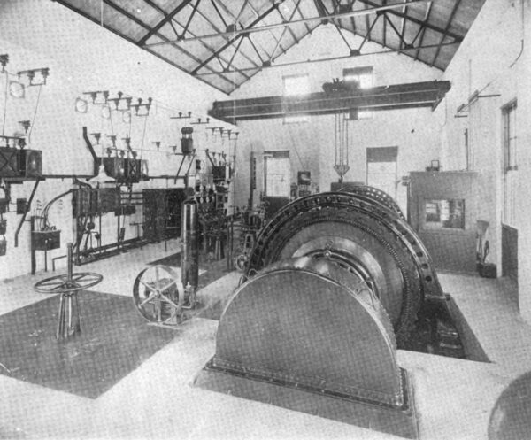
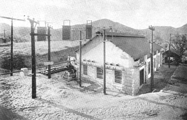
The transformers, each in a separate concrete cell, are placed in a concrete addition to the main building, also of concrete, with steel-trussed roof, as seen in Fig. 9, behind the iron-plate doors. Gauges enter the generator room, showing the height of oil and indicating any leaks in the water-cooling system. A flooding system, admitting water under high pressure to the bottoms of each transformer case, is provided in case any transformer should give serious trouble. Leakage from this system into the case under normal conditions is prevented by using two gates into each transformer flooding tap, a tiny hole to indicate leakage in the first gate being provided in the bottom of the pipe between the two gates.
| |||
| Fig. 9 Exterior of No. 3 Power House. Fire Proof Transformer and Lightning Arrester Cells in Lean-To |
One of the cells contains the lightning arresters which are of the General Electric zigzag, non-arcing, metal type, with series carbon resistances. These arresters are used throughout the system, one of the three slabs of which may be seen in the photo of Fig. 27. They have taken care of lightning discharges in a most perfect manner. It is worthy of note that these arresters are after all very little different from those in use twelve years ago, introduction of a series carbon resistance being the only change of note.
Intake and Conduit No. 2 and No. 1
From the tail race of power house No. 3 the water is at present discharged into the river bed of the North Fork, whence it flows to the simple intake of No. 1 at the junction of the North Fork and the South Fork of the North Fork. (The San Joaquin River has an enviable reputation for forks.)
At present a fall of 350 feet is running to waste in this river channel, but it is eventually planned to construct No. 2 system in this gap between the two present plants, as may be seen on Map II.
| |||
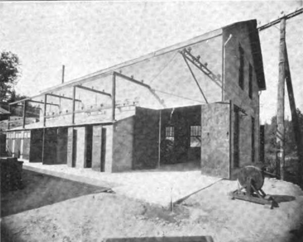
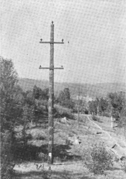
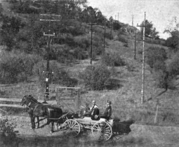
| Fig. 10 Looking North on Line Between No. 1 and No. 3 Power Houses, Showing Combination Pine-Cedar Stubbed Pole |
| |||
| Fig. 10a No. 1 Intake at Junction of North Fork and South Fork of the North Fork |
Nature was kind to No. 1. She provided a place in the North Fork where the waters could be diverted with little cost; she provided an easy country through which a dirt ditch could be cheaply constructed capable of carrying 75 second-feet, with a fall of 5.28 feet to the mile for seven miles; she provided a most charming ridge at the end of the line for a couple of miles of quite the right height and in a most opportune situation, ending in a sheer promontory especially designed by her for a pressure pipe. She even went so far as to provide a basin at the top of this declivity, so that at a cost of less than $3,000 an embankment 8 to 10 feet in height and 500 feet long was constructed to enclose a patch of about 8 acres, forming an ideal regulating forebay reservoir, conserving constantly a four days supply to No. 1. There is just enough land left to contain the residence of superintendent of the ditch system, who has lived on this upper crest since the plant was constructed, through twelve years of faithful service.
| |||
| Fig. 11 Regulating Forebay Reservoir for No. 1 |
From the entrance of the ditch into the reservoir a ditch is shunted around brow of the promontory, ending in an intake box in the pipe line to serve No. 1 in case of accident to the reservoir.
No. 1 Pressure Pipe Line
The pipe line down the rocky declivity to No. 1, 1,411 feet below, is 4,077 feet in length, consisting of four sections. The first, 960 feet in length, is of No. 12 b. w. g. riveted steel 24 inches in diameter. Following is 860 24-inch pipe of 1/4-inch riveted steel. Standard Converse lock-joint welded pipe 20 inches in diameter, with expansion joints, is used for the next 400-foot section, followed by 1,800 feet of 5/8x20-inch lap welded pipe with flanged joints. The whole is terminated with a 30-inch receiver 57 feet in length, constructed of 3/4-inch butt strap riveted steel with 3/4-inch rivets. The pipe is buried various depths, with the exception of the especially at the first real approaches of winter and expansion joints, which require inspection, summer. The pipe is anchored to the solid granite by means of 2-1/2x5/8-inch U bands, with split rods sulphured into the bedrock, besides many cement-collared anchors. The line has well withstood the twelve years of service with no trouble of importance, although a very early example of the solution of a then new problem.
| |||
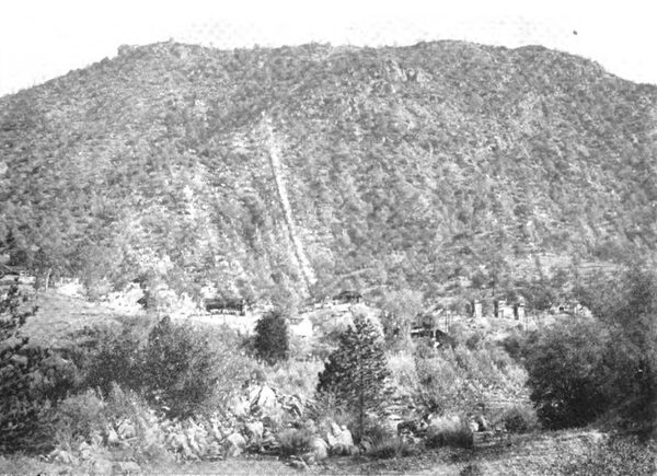
| Fig. 12 Pipe Line and Camp No. 1 Power House |
Power House No. 1
The No. 1 plant is of cardinal historic interest, as when it was put in operation in 1896 many anxious engineers heard with trepidation the fierce, harsh roar when water was turned on the first wheel, at 609 pounds pressure, at that time the highest head in the world.
The needle regulating nozzle was not in use at that time. The deflection regulating 14-inch nozzle, installed in the plant originally, may be seen in the scrap heap at the back of the power house.
One who may be fortunate enough to possess the early issues of the Journal finds much pleasure and profit in reviewing the April number of 1896, where early experiences with this plant are interestingly told.
| |||
| Fig. 13 Exterior Present No. 1 Power House, Showing Incoming No. 3 Line on the Right, Choke Coils on Poles and Lightning Arrester Sheds on the Left |
Of the original power-house equipment, the generators only remain as then installed, there having been added to the three 350-kw., 60-cycle, 700 volt, 600 r. p. m. General Electric generators a similar 360-kw. machine of a more recent make.
The old air-ventilated transformers have been replaced by six 200 kw. General Electric air-blast transformers, cold air being taken from the tail-race tunnel for the blast, as in this locality, in the bottom of a canyon so crooked that wind has some difficulty in blowing through it, the summer days are excessively hot.
Latterly four 200-kilowatt, oil-filled, water-cooled transformers have been installed, forming a 5-phase set with one reserve, which can be used with any of the other sets, and stands hot in readiness for such service. Type IF, Lombard-Replogle mechanical governor and a Tirril regulator serve to keep variations of speed and voltage to a minimum.
| |||
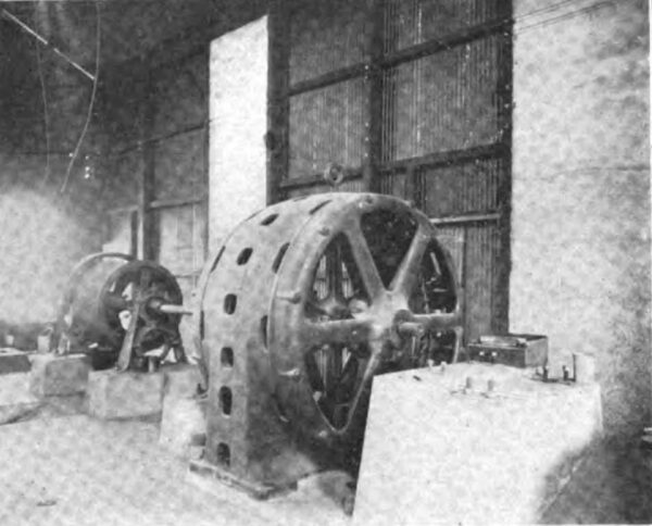
| Fig. 14 the New No. 1 Generators Only Remain of the '96 Equipment |
In the rear of the view of Fig. 14 may be seen the line from No. 3 entering the station in the left corner and the two duplicate lines leaving for the valley, through the rear wall. Kellman oil-break switches and a double set of busses serve to switch these three circuits into any desired combination. It is noticeable that the generators are not provided with fuses or circuit breakers, the generators being connected solidly into the line.
| |||
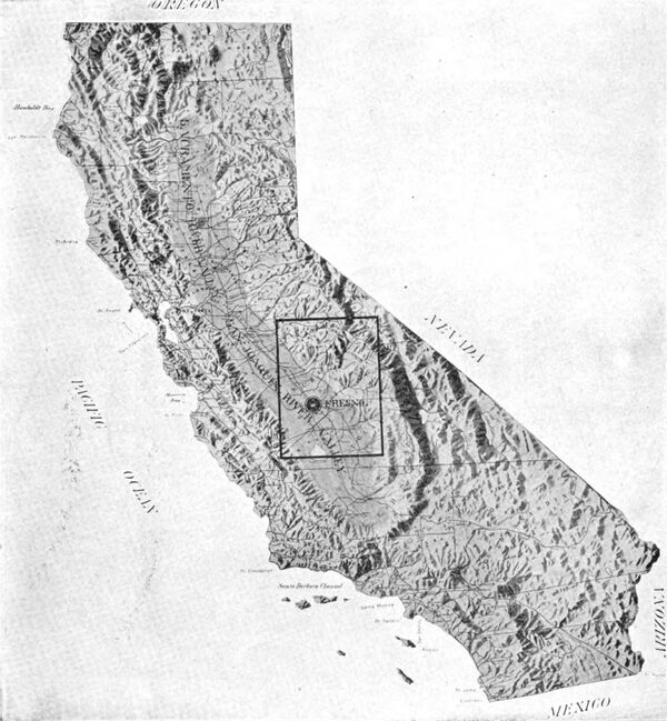
| 1. Relief Map of the State of California |
 |
Transmission Lines
The exterior station view of Fig. 9 shows the transformer rooms of No. 3, the farthermost source of power on the system and the location of an instructive accidental Lines test of the insulating qualities of snow. Above the transformer sheds shown at the left, with iron-bound doors, the 30,000-volt lines leave for plant No. 1 and the valley. At one time these wires and insulators were entirely covered with an unusually heavy fall of snow on the roof, some three feet in depth, while no effect on the operation of the lines could be noticed.
From this plant a 30,000-volt line of three No. 0 wires extends 7-1/2 miles to the original No. 1 power house, the construction of which is interesting in that home products, with the exception of Mexicans for ground men, were used in its construction. The pine poles were supplied in the immediate vicinity. No attempt was made to put these poles in the ground, on account of their quick decaying qualities. Stubs 10 inches square and 10 feet long were sawn from the heart of fall-cut cedar, which grow in lesser numbers in the neighborhood. To these stubs, by means of two 3/4-inch U bolts and armature, the pine holes were bound, as may be seen in the photo of Fig. 10. Three years of service have developed no trouble. This line enters the old original power house No. 1 through an oil switch to a double set of busses, shown in the extreme end of the building of Fig. 14. Connecting with these busses also are the leads from the step-up transformers of No. 1, so that the current from No. 3, as well as that coming from within No. 1, may each be switched to either of the duplicate lines down the valley.
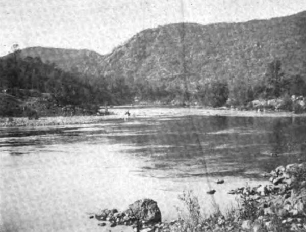
| |||
| Fig. 15 the San Joaquin at No. 1 Power House |
| |||
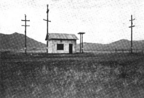
| Fig. 16 West and East Mines, No. 1 to Fresno, 34.4 Miles, Tap - in Telephone Station on Old (West) Line of 1896 |
| |||
| Fig. 17 Clovis Switching Station and Lines to Fresno |
Referring to the map, it will be seen that from this power house extend southward two transmission lines for the greater part on the same right of way, as viewed in Fig. 16, to a point where the fertile level floor of the valley meets the rocky foothillsthe first stepping stones to the high Sierras. Once the source of wondrous wealth in the placer sands of the interlaced washes, these foothills give little evidence of the exciting days of 49.
At present a lonely copper mine is the sole mineralogical survivor of the particular locality. The mine derives its power from transformers in a small sub-station near the switching station of Figure 17.
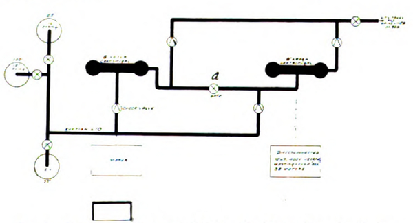
The switching station, located at the beginning of the distribution of power, is an important engineering featurea nervous center, as it wereof the system. For here the duplicate lines from No. 3 and No. 1, the line skirting the valley to Madera, and those over the floor to Fresno, Corcoran, and Cottonwood Creek, may be switched each to the other in various permutation.
| |||
| Fig. 18 Interior Clovis Switching Station |
The six circuits mentioned above, including the copper mine sub-station, enter the gable of the concrete structure, 18 wires in all. Each circuit is connected both to the bus on the north side and the bus on the south side of the concrete building, by means of disconnecting switches and oil switches. By this means any circuit may at any time be connected to any other in a thoroughly flexible manner.
Reference to the map and to Figures 10, 16, 24, 25, and 33 will give a very comprehensive idea of the transmission lines.
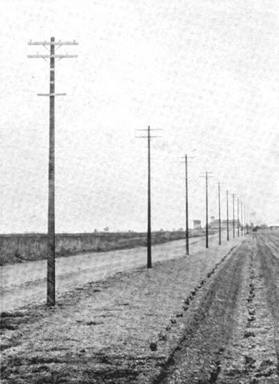
The poles between No. 1 and Fresno are cedar, as may be seen in the east line of Figure 16. This also shows the west line, which was transformed from a 2-circuit line of No. 3 wire, as shown in Figure 20, to a single circuit by twisting the wires together to form a 2-strand cable. This line has required little stubbing, thus showing the superiority of square redwood poles when properly selected.
Long span work has been used, with success, under the mild climatic conditions of this section.
| |||
| Fig. 19 500 H. P. Westinghouse 3 Phase Motor at Copper Mine Near Clovis |
| |||
| Fig. 20 the Old '96, 11,000 Volt Double Line Vanishing Toward Fresno |
Between Clovis and Fresno, every other pole of the original line has been removed, making the spans 240 feet, while the line to Madera from the Clovis switching station is composed of 250-foot spans. The line from Fresno to Kerman of No. 6 wire has its spans 350 feet in length for 12 miles and 250 feet long for the five miles nearest Kerman. For many small branches off the 4,000 and 6,600 volt lines, iron wire with 500-foot spans is common.
Fresno Substation and Steam Reserve
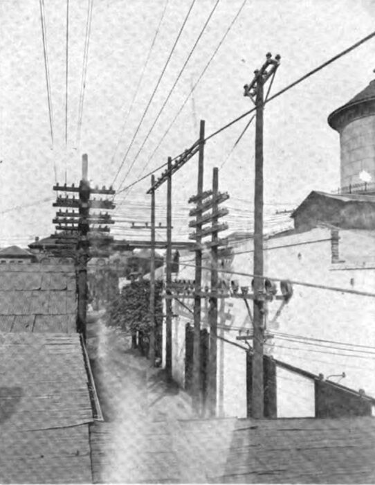
In the formidable array of wires in Figure 21 we see the 30,000-volt lines entering the Fresno substation and the 30,000-volt feeders leaving Kerman and down the valley through Hanford. The city 2,000-volt distributing-system wires are also shown, while the 250,000-gallon tank mentioned in connection with the Fresno water system, under other pages, is seen in the extreme right field.
| |||
| Figure 21 Two, 30,000 Volt Line for No. 3 and No. 1 Entering Fresno Sub. Two, 30,000 Volt Lines Leaving Fresno Sub. for Kerman and Hanford. Behind Iron Doors Are the Fire Proof Transformers and Lightning Arrester Cells |
Underneath the tile behind the iron doors, in individual compartments, separated by a concrete wall from the interior of the sub-station, are located the nine oil-filled, water-cooled transformers for supplying Fresno with power. Three 200-kilowatt General Electric 30,000 to 2,300 volt transformers convert to a 3-phase, 4-wire system of 4,000 volts or 2,300 volts, being thus connected in Y on both sides. Six 500-kilowatt transformers, two being of Stanley make and four of Bullock manufacture, transform from 3-phase of 30,000 volts to the 3-phase, quarter-phase system shown in Figure 23, which will shortly be described. Two banks of lightning arresters of the type seen in Figure 27 are also enclosed in this compartment. Above these transformers and lightning arresters is the 30,000-volt oil-switch and bus-bar gallery within the station proper, seen in the background of Figure 22. A double set of bus-bars renders this an oil-switching station similar to the one at Clovis, but of less complication. Within the station one finds the feature most worthy of note,a double set of synchronous motor generators for supplying the Fresno Traction Company with direct current.
| |||
| Fig. 22 Fresno Substation |
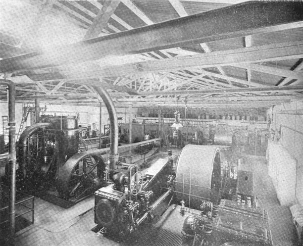
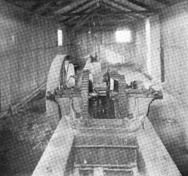
One 300-kilowatt General Electric and one 200-kilowatt Westinghouse synchronous motor generator set performed this function, being so connected through a positive clutch on either end of a pulley that they may be operated by a 750-horsepower MeIntosh & Seymour cross-compound condensing engine in case of trouble or shortage of power. In such an instance the synchronous motor sets are used as 3-phase generators as well as the d. c. generators. The output in such case at full load might reach 1,000 kilowatts, which is sufficient excuse for the exceedingly large belt seen in the foreground of the interior view of the station. The six-foot belt shown in Figure 22 stands constantly ready for this obscured by a belt tightener, in itself an instrument of quite formidable design.
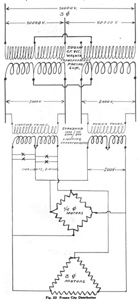 |
| Fig. 23 Fresno City Distribution |
 |
| Fig. 24 Recent 30,000 Volt Construction With 4,000 Volt 4-Wire System and Telephone System Below |
We find also a 600-horsepower Union Iron Works compound, non-condensing engine, belted to two 180-kilowatt, 2,300-volt, quarter-phase Westinghouse generators for reserve purposes on the quarter-phase city circuits.
Steam is constantly in one of the boiler batteries, composed of two 500-horsepower and two 350-horsepower Babcock and Wilcox boilers, in case of trouble.
Other Substations
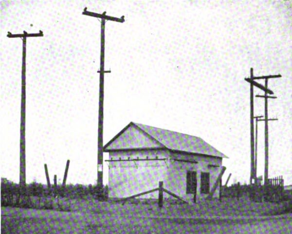
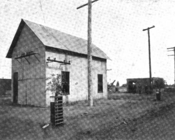
In the views of Figures 26 and 27 we find a representative of the smaller sub-stations outside of Fresno, which contain oil-filled, air-cooled, 30,000-volt transformers, lightning arresters, oil switches, and integrating wattmeters. This particular station supplies the towns of Selma, Fowler, and Kingsburg, containing three 100-kilowatt, 17,300 to 2,200 volt Wagner transformers, connected YY, for a 4-wire, 3-phase secondary system. A duplicate of this equipment is to be found in the Madera, Corcoran, and Reedley, white at Stone Corral and same capacity is installed in 17,300 Y to 6,600 volts.
 |
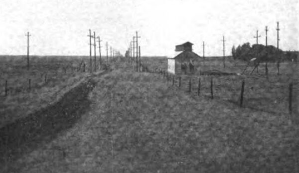
| Fig. 25 Construction 3 Years Old From No. 3 Power House to Fresno 41 Miles |
| |||
| Fig. 26 Selma-Kingsburg Substation |
| |||
| Fig. 27 Selma Substation |
At Hanford, three 133-kilowatt transformers of a similar type convert to a delta distribution at 2,300 volts, supplying Hanford and Armona, while 50 and 75 kilowatt transformers are located in the sub-station of Laton and Kerman.
The sub-station at Copper Mine is of a different type, containing air-blast transformers connected in Y on the primary and in delta to give 500 volts for motor work on the secondary.
Distributing Systems
Distribution to light and power in the city of Fresno is effected at 2,000 volts, stepping down by means of standard transformers for lighting at 100 and 200 volts and to motors of 200 and 400 volts.
| |||
| Fig. 28 Selma Pumping Plant, of Ice, Storeroom , Shops, Etc. |
| |||
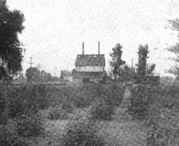
| Fig. 29 Selma Gas Works and Young Eucalyptus Grove |
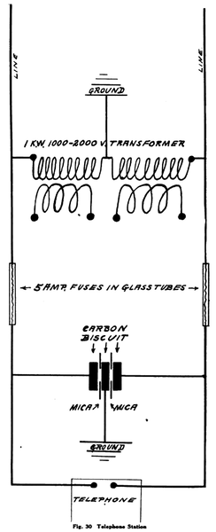 |
| Fig . 30 Telephone Station |
Circumstances obtaining from time to time during several years past have caused the introduction of both three and quarter phase motors in the city of Fresno. The resulting complication has been solved by the company in the simple manner diagrammed in Figure 23. The company specifies that 400 volts should be used in motor installations of 50 or more horsepower, in which case separate but standard 2,000 to 400 volt transformers are used in a fashion similar to the above diagram. Recent and present practice is confined to the installation of 3-phase motors wherever possible. Westinghouse 2,000-volt lightning transformers are used throughout, with General Electric primary cut-outs.
Distribution in towns or districts outside of Fresno is effected by the employmet of 4,000 and 6,600 volts.
For the towns of Madera, Fowler, Selma, Kingsburg, Reedley, Dinuba, and Corcoran, and environs, the 4-wire star-connected, 4,000-volt system for primary distribution to lights and motors is employed; so that single standard 2,000-volt transformers may be connected for lighting between the neutral and either of three main wires, while three transformers in are used for motor installations and short transmission work.
In the city of Hanford and in Kerman, Laton, and Armona, a 2,300-volt, 3-wire primary system is maintained.
| |||
| Fig. 31 Madera Substation and City Pumping Plant |
 |
| Fig. 32 Diagram of Madera and Selma City Water Pumping Station |
| |||
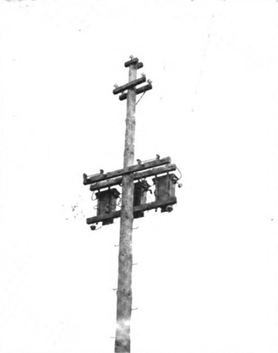
| Fig. 33 Stone Corral Substation Showing 6,000 Volt, Iron Wire, 500 Foot Span Line Towards "Look-Out Mountain," at the Left. Three, 100 K. W. 17,300 - 6,600 Volt Transformer |
6,600-volt transformers are used in secondary delta on line extending from the Stone Corral sub-station over a new and fertile citrus district. This system includes 18 miles of line having small No. 9 iron wire branches with 500-foot spans. The main lines of this particular system are of No. 6 copper, with 350-foot spans, and no telephone wires. At the farthermost point, 10 miles as a wireless line would run, from Visalia the current is transformed to 200 volts for the use of a 40-horsepower motor, which supplies water for the beautiful ranch of the Redbanks Orchard Company, containing 700 acres planted to grapes, peaches, pears, prunes, plums, and a very extensive nursery stock. Although 30,000-volt lines in the beautiful cajon of the Stone Corral Valley, it was here that the world-famed bandits, Evans and Sontag, received a paralyzing shock. We see the highest peak of the ragged edge their Stone Corral is now developing as a fruitful power sink, with its many hundreds of acres of newly planted citrus land.
At the end of the 6,600-volt line in Cottonwood Creek there is also great activity in newly established citrus farms. This 6,600-volt system from Stone Corral to Cottonwood is now delta connected. Eventually it will be changed to a 10,000-volt Y-connected system, in common with many branches which are now 4,000, tending toward a universal secondary-power voltage of 10,000.
| |||
| Fig. 34 Typical Orange Grove Pumping Plant Stone Corral" Off of 6600 V Line. |
The fuse employed on the 6,600-volt circuits is a shellacked stick of maple 12 inches long between clips, something after the fashion of an enclosed fuse, but diamond shaped in cross section. Wrapped around it are the protective fuse. New ones are being constructed with an insulator at the middle point, into which a threaded stick may be inserted for switching or renewing.
On the 400-volt primaries the General Electric fused primary cut-outs are used throughout the companys properties.
Telephone System
Communication between the two hydraulic plants and the various sub-stationsfrom the sugar-beet fields at Corcoran, around Lake Tulare, through Fresno, to the System pine-rimmed camp at the Crane Valley Reservoir, a hundred miles distantis exceptionally safe and satisfactory; the noisome inductive humming usually present in connection with long-distance transmission systems being quite thoroughly eliminated.
 |
| Fig. 35 6600 Volt Transformer Hanging for Orange Ranch Pumping Plant of the "Stone Corral" |
| |||
| Fig. 36 6600 Volt Transformer Hanging at End of 600 Foot Span, for Construction of New Crane Valley Dam. |
The diagram of Figure 30 illustrates the manner of obtaining these results, by the use of a small standard transformer whose primary windings are placed in series as on a 2,000-volt system, the connection. between them being grounded, while the secondary of the transformer is left open. Magnetic and static induced electro-motive forces, which in some systems reach very high values, are here entirely absent, the currents being continuously discharged to ground through this repeating coil of high resistance, with no effect upon telephonic communication. This method is also in use on the Kern River line to Los Angeles, where the normal inductive voltage on the line was reduced from 2,000 to 28 volts to ground by the introduction of transformers.
| |||
| Fig. 37 Finlanders 78 HP. Pumping Plant for 478 Newly Tilled Acres |
The discharge due to lightning, or by virtue of a cross with the 30,000-volt line, arcs to ground between two 3-inch carbon biscuits 5/8-inch in thickness and through a hole an inch and a half in diameter in a 1/32-inch sheet of mica placed between them, thus blowing the fuses and protecting the operator and the phone. The carbon biscuits are set to discharge at 500 volts alternating current, which adjustment they permanently and accurately maintain.
Since the introduction of these devices, three years ago, no one has received injury, nor has a phone been disabled by such usual sources of trouble, with the exception of one instrument which was not so protected when a cross occurred between the telephone and the 30,000-volt linea very convincing proof of the effectiveness of the method.
| |||
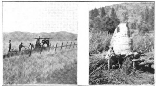
| Fig. 38 Farming of Today, Ploughing in the "Stone Corral Fig. 38 Farming of A Thousand Years Ago. Here the "Diggers" and the "Monos" Store the Acorns for Grinding Into Meal. |
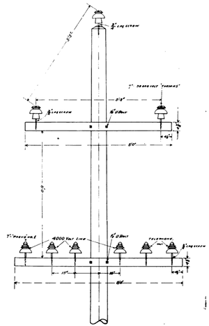
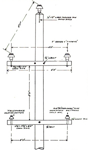
The new telephone line wires are of No. 11 B. & S. copper, while the old original wires are of No. 14. They are placed 5 feet below the lower 30,000-volt wires and on a cross-arm 5 feet 3 inches apart. The insulators consist of high-voltage culls and the old Redlands Type porcelain ones used originally on the 11,000-volt line of 96. (Figure 20.)
From Fresno to power house No. 1 there is a telephone line on each transmission line, as shown in the views of Figure 16, one of No. 11 and the other of No. 14.
It will be recalled that the transmission lines, whether of 30,000, 6,600, or 4,000 volts, are entirely free from transpositions. The telephone line, however, is transposed at 10-pole intervals. Where the poles are 240 feet apart, as on the lines between Fresno and the Copper Mine station, the distance of 2,400 feet between transpositions is much greater than is usual.
We thus find here another the tendency toward combined simplicity and reliability, so neatly illustrated throughout the properties of the company.
Water Systems
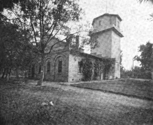
The power company also furnishes power to operate the domestic water supply systems of Madera, Selma, and Fresno. In the former town, of some 2,000 inhabitants, the system of nine miles of water mains and lateral ramifications has its source in a simple although reliable and efficient pumping plant at the edge of town, while the two water tanks are some distance the small, neat brick station, which is half aboveground and half a water-tight pit below the surface, shown to the right in the photo of Figure 31, is a most interesting pumping plant. It consists of two similar Krogh horizontal centrifugal pumps, each direct connected to 3-phase motors, the diagram of the pump connections being shown in Figure 32.
| |||
| Fig. 39 U.S. Government Reclamation Service Pumping Plant. 80 Acres in Foreground Reclaimed by "Leaching" Process From Alkali. |
| |||
| Redbanks Orchard Co. Ranch and Nursery 700 Acres Planted, 500 Acres in Contemplation |
Under normal circumstances either pump may be operated at 45 pounds pressure, or thereabouts, the tanks up town floating on the system with the pumps in continual operation. By opening the gate a the dormant pump may be started up in case of fire, thus putting the two in series to produce a pressure of 90 or more pounds. As a result of this arrangement, no fire engines are used in either Madera or Selma.
The motors are equipped with Westinghouse no-voltage and overload oil-break circuit breakers, and controller type auto-starters.
Thus with the automatic nature of the centrifugal pump at constant speed, furnishing widely various quantities of water at a very constant pressure, at the invariable speed of the motors, the station is well equipped to run cheerfully alone day in and day out, with that perfect understanding which exists betwixt an induction motor and a direct-connected centrifugal pump, although rivals in effectiveness and reliability.
The arrangement at the Selma plant is almost identical with one at Madera, and alike in the satisfaction which it gives. The Selma system threads the town with 9-1/2 miles of piping, supplying a population of 2,500.
The water system of Fresno contains similarly interesting features. The 47 miles of system are supplied by six pumping plants at widely separated points, each containing a direct-connected centrifugal pump, one or more of these pumps floating in parallel 250,000-gallon tank. This supplies, through practically a ring system, a large volume of water from several different directions to a fire engine at any particular point with a system of interconnected mains, maintaining a constant pressure practically automatically with varying demands. Analogous to electrical phraseology, this is purely a parallel system, since engines are used for fire protection, as distinguished from the series system of pump connections in Madera and Selma.
Gas System
A short distance from the water plant for the town of Selma, the power company also operates a gas plant, which is seen in the view of Figure 14. Thirty thousand feet of crude-oil gas per day is being supplied to a system of seven miles of mains and laterals. Some 3,000 eucalyptus, of the red gum variety, are being grown around the gas plant to partly absorb the odorous smells and waste obscure from sight the source of the waters and to same.
Power Sinks
here are things for the economist to think about around Fresno, where thousands of acres of land are being newly cultivated and brought under artificial irrigation by means find at the copper mine, which has been of pumping plants. Here we already mentioned, the installation of a 500-horse-power induction motor, which is the largest on the system. In one planing mill in Fresno there is consumed 190 horsepower in the 15 motors it operates, while another mill in Fresno utilizes 225 horsepower in 18 units. The Dinuba mill subscribes for 40 horse-power, while a flour mill at Selma consumes 50 horse-power.
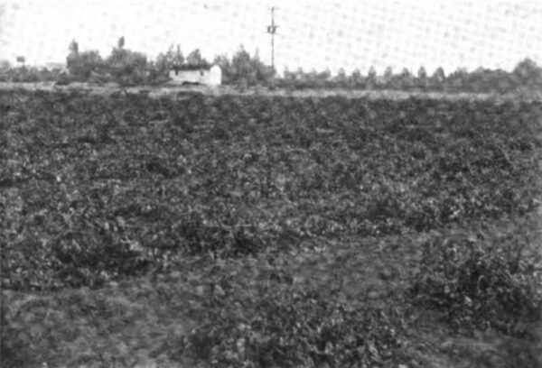
In Figure 3 plant off the 4,000 line from the Reedley sub-station, is shown a 75-horsepower pumping which lifts water from the Kings River for irrigation of 478 acres recently purchased by a colony from far-off Finland. The cost per acre for this irrigation is $1.65 annually, for a constant year-around supply. A 15-horsepower plant supplies 110 acres adjoining the other tract belonging to the same colony.
The Redbanks Orchard Company, having recently brought into bearing 700 acres of choice foothill land planted to all kinds of deciduous vines and trees, now uses a 40-horsepower motor for pumping. These are a few instances of a large number of plants similarly operated.
The Corcoran sugar plant has a 300-horsepower motor installed, while the Italian-Swiss Colony winery near Madera uses 100 horsepower, including a centrifugal plant for pumping wine.
A local distributing company at Hanford consumes from 400 to 500 horsepower, which is used for lighting and power purposes, including the pumping of water for city use and the operation of the flour mill.
Hundreds of horsepower are used in the many packing houses for seeding raisins, sorting, packing, telpherage, etc.
The Fresno Water Company is one of the larger consumers, absorbing annually current to the amount of $35,000.
The Fresno Traction Company, another large customer, consumes about half the above amount at present. Rapid demands of the traveling public have made necessary many extensions, so that in a short time a 30-car system will consume about $50,000 yearly in electric power.
The energy is supplied by the 300 and 200 kilowatt synchronous motor generator sets in the Fresno sub-station, as was described under the caption.
These various users of power at the present time are 5,786 in number, which does not include the customers in Hanford and Armona nor the gas consumers in Selma.
Prices for Power
In the city of Fresno we find established the low base rate of $0.09 per kilowatt-hour, from which reductions are made to as low as cents for large users consuming Power current under favorable conditions. Throughout the rest of the system the base rate is $0.10, ranging as low as $0.05.
For power purposes the rate is universally between $0.013 to $0.05 per kilowatt-hour, thus fostering the largest and most reliable and lucrative custom.
Retrospective, Prospective and Statistical
The oldest inhabitant of Fresno need not be of very mature age. The man of forty can well remember when the Southern Pacific laid the rails through the San Joaquin in 1872, thus giving an excuse for a station on the line called Fresno. To a Californian this thirty-six years since seems much more than enough to build a city of twenty times the size of Fresno, with its 35,000 inhabitants. It is, however, a matter of wonderment to note the agricultural development of the section lying around the city, threaded by the wires of the San Joaquin Light and Power Company, not only in Fresno, but in neighboring counties. This section can undoubtedly prove a greater agricultural development and production in dollars per capita per year than any other district of equivalent area. The ratio, as near as can be calculated, is quite near to $41,000,000, divided by 50,000 souls, or about $820 per capita per annum. A combination of many causes is responsible for such progress, the most potent being fertility of soil, an abundance of water in an ample irrigating canal system, a favorable climate and geographical situation to preside over the commerce of the San Joaquin Valley, quite level and hence easily irrigated lands, an energetic people, and last, but not least, cheap and available electric power.
 |
Fresno is not only feeling a vis-a-tergo from the importation of this $41,000,000 per year to pay for the crops and products sent to many foreign and domestic parts, but also on account of the importation of nascent moneys for the development of large new tracts of land of the general type of the Redbanks Orchard Companys properties on the Cottonwood.
These fertile foothill slopes above the frost, and also above the irrigating canals, are especially adaptable for citrus fruits as well as all kinds raised down m the lower levels. Lands of this kind are of sufficient acreage to demand from 50,000 to 75,000 horse-power for their development, and in the industries which would appertain thereto, lands which are absolutely dependent for all time upon power for their cultivation and their commercial existence.
The impetus given to the Calmyrna fig industry by Mr. Roeding, of Fresno, who studied the cultivation in the native country of Symrna, as mentioned in the introduction, is shortly to add much credit to this well-adapted district.
The cultivation of the olive is also of growing importance, 1,000 gallons of oil being produced last year.
| |||
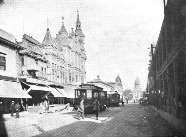
| Fresno Street Scene |
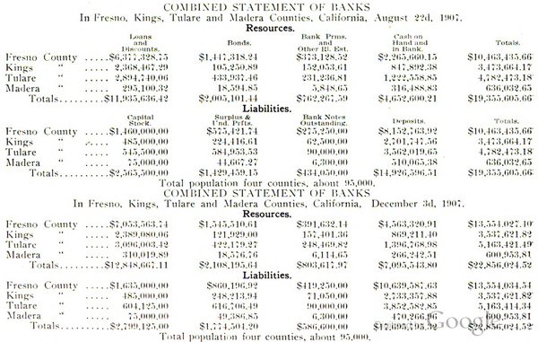
These and many other facts naturally turn one's attention to those who have to do with the large sums of money necessary to handle the crops. During the late financial unpleasantness this section was quite oblivious of its existence, as a study into bank statistics, made by the examiners at the time, indicated in the first call of statements from the national banks, in December, 1907, a more healthy condition than in the preceding August reports.
