[Trade Journal]
Publication: Electric Railway Journal
New York, NY, United States
vol. 33, no. 3, p. 92-97, col. 1-2
PITTSBURG, HARMONY, BUTLER & NEW CASTLE
1200-VOLT, D. C. RAILWAY
BY JOHN R. HEWETT
Although the Indianapolis & Louisville Railway was the first to be put into operation in this country with a potential of 1200 volts on the trolley, the Pittsburg, Harmony, Butler & New Castle Railway can claim the distinction of really being the pioneer road in this direction, as the plans and specifications for it were prepared at an earlier date. Both of these roads are under the same management and were built by the same engineer. James Bryan, of Pittsburg, is consulting engineer for both roads and was responsible for the choice of 1200-volt apparatus, and his faith in it has been well justified by the results attained. The personnel of this railway is as follows: President, R. H. Boggs; vice-president, W. A. Goehring; superintendent, H. Etheridge; engineer of power house, C. A. Houghton. The map shows the districts served and the location of the power house and substations.
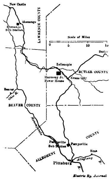 |
| Pittsburg 1200-Volt Line — Map of Pittsburg, Harmony, Butler & New Castle Railway |
The general scheme of electrification is as follows: Power is generated at Harmony Junction at 13,200 volts, 60 cycles, and fed to the Shenango and Perrysville substations by the trans-mission line at this potential. A substation in the power station takes care of the center portion of the system. The Butler section is fed by feeders. Synchronous motor generator sets in the substation transform the high potential alternating current to 1200 volts direct current, which is the working potential of the trolley.
| |||
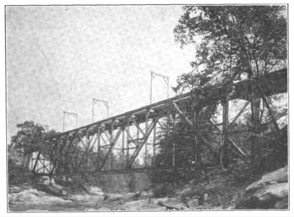
| Pittsburg 1200-Volt Line — Buhl Bridge |
The more important distances are New Castle to Shenango substation, 4.8 miles ; Shenango substation to power house, 19 miles; power house to Perrysville substation, 21.75 miles; Perrysville substation to Pittsburg, 4.25 miles. The distance from the power house to Butler is 15 miles.
| |||
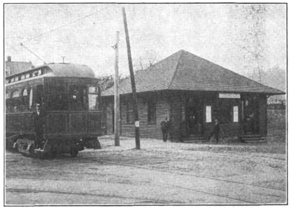
| Pittsburg 1200-Volt Line — Ellwood City Depot |
All of the system is operated on 1200 volts, with the exception of approximately 4 miles at the Pittsburg end, where the cars run over the city lines, which are operated at 600 volts.
POWER HOUSE
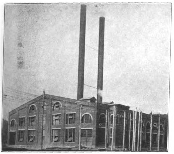
The power house is located at Harmony Junction, and its principal dimensions are as follows:
Engine room length, 120 ft.; width, 49 ft.; height to roof truss, 31 ft.; to apex, 47 ft.
Boiler room length, 120 ft.; width, 57 ft. 6 in.; height to roof truss, 31 ft.; to apex, 47 ft.
The more important items of electrical equipment are:
Two A. T. B. 8-pole, 1500-kw, 900 r.p.m, 13,200-volt, 60-cycle, vertical Curtis turbo-generator sets.
Two bipolar, 25-kw, 3600 r.p.m., 125-volt, horizontal Cur-tis turbine exciter sets.
The turbines are standard General Electric four-stage machines, with two rows of buckets per stage, and have mechanically operated valves and oil step bearings. They operate condensing, the usual vacuum attained being 284 in. or better. The exciter sets operate non-condensing.
| |||
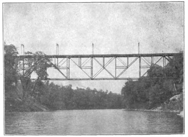
| Pittsburg 1200-Volt Line — Grimm Bridge Spanning Connoquenessing River |
Among the auxiliary apparatus may be mentioned two jet condensers, two horizontal feed pumps, two centrifugal circulating pumps, two horizontal air pumps, two horizontal step bearing pumps.
All of these pumps are steam driven and were built by the Worthington Company.
A substation is located in the power house, but as the apparatus installed is similar to that in the other substations, it will be described later.
| |||
| Pittsburg 1200-Volt Line — Exterior of Power House at Harmony Junction |
The present capacity of the power house is 3000 kw, but if conditions should warrant the installation of more apparatus, one of the end walls will be removed and additional turbines placed on the other side of the substation apparatus, leaving the present substation in the middle of the power house. The present boiler equipment consists of four Babcock & Wilcox water-tube boilers, each of 480 hp, with a working pressure of 200 lb. per sq. in. These are arranged in two batteries and are hand fired.
| |||
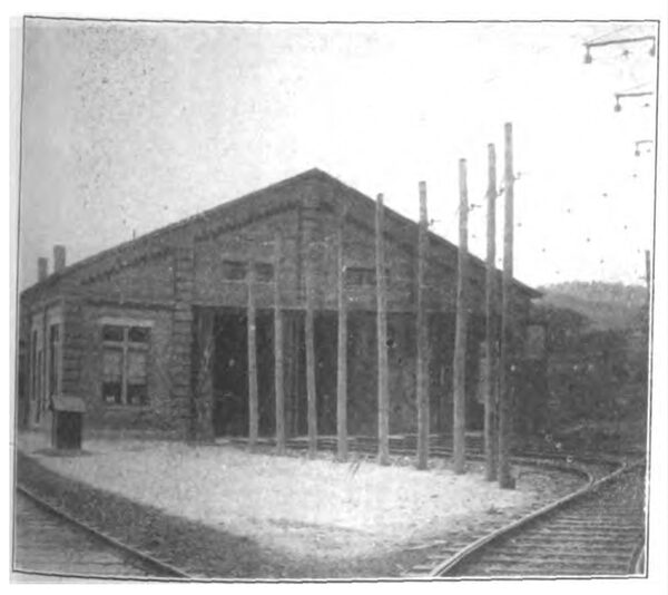
| Pittsburg 1200-Volt Line — Exterior of Car House at Harmony Junction |
The coal handling apparatus is simple, consisting of a pit running the length of the power house, with rails laid above, so that the coal can be dumped direct. A series of arches open from the pit to the boiler room floor. It may be of interest to note that the company has a coal mine immediately outside the power house, and coal is dumped directly into the coal bin.
SUBSTATIONS
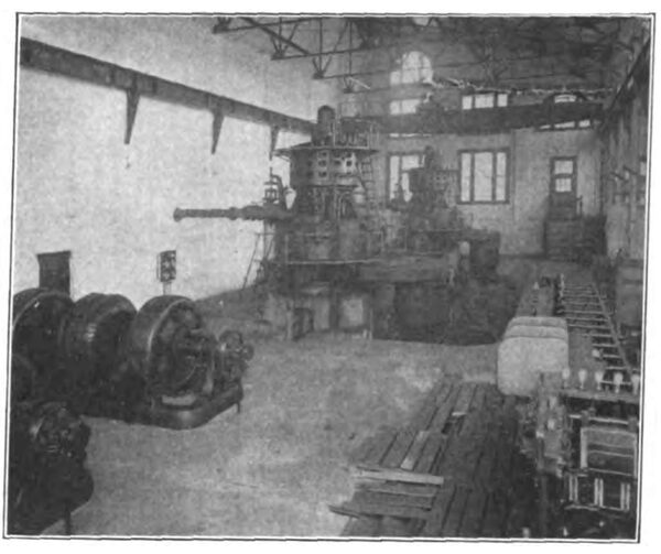
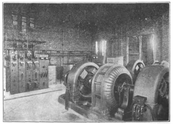
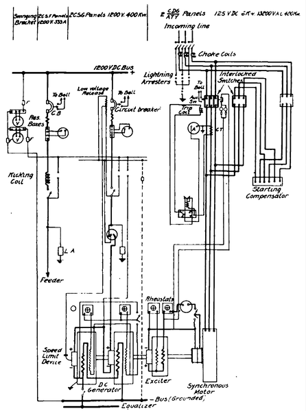
There are three substations-one in the power house, one at Shenango and the third at Perrysville. The electrical equipment is the same in each, and includes three General Electric motor generator sets, each consisting of two 4-pole, 200-kw, 720-r.p.m., 600-volt, direct-current generators, direct driven by and mounted on the same base with one A.T.B. 10-pole, 425-kw, 13,200-volt synchronous motor. A 6-pole, 6-kw, 125-volt exciter for the synchronous motor field is mounted on the same shaft. Each motor generator has its own starting compensator.
| |||
| Pittsburg 1200-Volt Line — Interior of Power House at Harmony Junction |
The switchboard in each substation comprises two 400-kw, 13,200-volt synchronous motor and exciter panels; two400-kw, 1200-volt, d.c. generator panels; two 400-kw, 1200-volt, d.c. feeder panels, and two 1500-volt voltmeters and brackets. The three-phase lightning arresters are of the multiple gap type. All of the oil switches in the substations are of form K-4.
The synchronous motors are started up on the a.c. side with the compensators in circuit. When full speed is attained the compensator is cut out and the motor direct connected to the 13,200-volt buses. The oil switches controlling these connections are interlocked to prevent the motors being thrown direct on the full voltage when starting up from rest.
| |||
| Pittsburg 1200-Volt Line — Span Construction Near New Castle |
The armatures of the d.c. generators are connected in series, with one terminal grounded, giving 1200 volts on the feeder bus to which the other terminal is connected. The generator fields are also connected in series through a single equalizer bus, to insure both machines taking a correct proportion of the load.
TRANSMISSION LINE
The working potential of the three-phase transmission is 13.200 volts and the frequency 60 cycles per second. The three wires are arranged in the form of an equilateral triangle, with sides 30 in. in length. An aluminum wire built up of seven strands and having a current carrying capacity equal to that of a No. 2 B & S copper wire is used.
| |||
| Pittsburg 1200-Volt Line — Luntz's Bridge |
Each transmission line cross-arm is a single malleable iron casting of a circular cross-section, with the ends turned up for the reception of the insulator pins. It is attached to the pole by one through bolt and one lag screw which pass through the double lug cast integral with the cross-arms. The porcelain insulators were manufactured by R. Thomas & Son, and were tested to 30,000 volts. The insulator pins, which are of galvanized steel, are attached to the porcelain by cement, and in the case of the two lower insulators are screwed into the malleable iron casting. The top insulator pin is screwed into a circular malleable iron flange, which is in turn fastened to the top of the pole by three glavanized barge spikes. This flange also forms a weatherproof cap for the pole.
The total length of the transmission line is approximately 41 miles.
OVERHEAD CONSTRUCTION
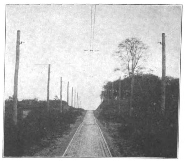
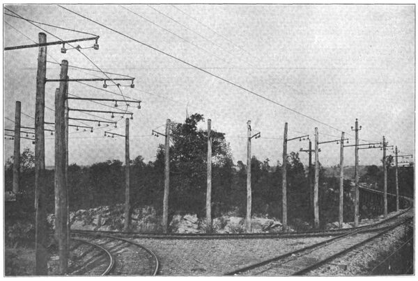
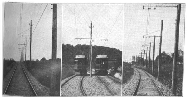
The overhead construction shows some radical departures from standard practice. The material employed was manufactured according to the designs patented by James Bryan and H Etheridge. A grooved No. 0000 copper trolley is used, and this is strung double the entire length of the road, the distance between the two wires being 5 in. and the height above the track is 19 ft. 6 in. Single bracket construction has been adopted throughout for single-track work, and there is very little special trolley work anywhere on the system. The poles are 35 ft. in length and are buried for a distance of 6 ft. in the ground. On tangent track the pole spacing is approximately 82 ft. On curves the spacing is considerably less, and although this involves the use of a large number of poles per mile, it eliminates all guys and anchors on curves. In all cases the pole spacing is arranged to bring the trolley wire immediately over the center of the track. On the double-track portion of the road a double bracket construction is used.
| |||
| Pittsburg 1200-Volt Line — Ellwood City Y |
Referring to the details shown in the drawing, the bracket is built up of a malleable iron casting which has a circular cross-section and is screwed into a length of 2-in. iron pipe. This casting is 38 in. in length and is standard for all work, while the length of the pipe varies from 53 in. to 57 in. to suit the lean of the pole. A screwed flange is furnished at one end of the bracket for attachment to the pole. This is effected by a bolt at the top, which passes through the pole, and a lag screw at the bottom. The free end of the bracket is provided with a lug for the reception of a 5/8-in. stay rod.
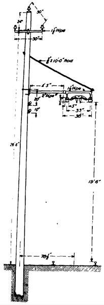 |
| Pittsburg 1200-Volt Line — Standard Bracket Pole Construction |
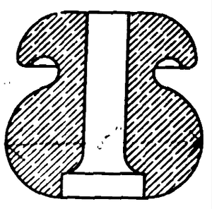
A section of one of the insulators is also shown; they are of porcelain, and measure 5 in. in diameter and 5 in. in height. The insulator pins are in the form of a metal pipe, one end of which is screwed into the malleable iron casting and the other flared to a bell mouth to conform with the shape of the insulator. The insulators are attached to the pins by cement.
| |||
| Pittsburg 1200-Volt Line — Porcelain Insulator |
In the towns, where span construction is adopted, the trolley is doubly insulated by insulators like those on the brackets on the poles, and also by goose-egg insulators inserted in the span wires on both sides of the ears.
FEEDERS
The feeders for supplying the Butler section are of stranded aluminum. For the first 7 miles the cable has a capacity of 500,000 circ. mil, and the second cable, which is strung parallel to the first, is 10 miles in length and has a capacity of 750,000 circ. mil. These cables are carried on the poles which support the trolley wire.
ELECTRICAL EQUIPMENT OF CARS
At present there are 14 four-motor passenger equipments in operation, and two additional cars for carrying freight will be put into service in the near future. The electrical equipment, so far as motors and control are concerned, are similar on both passenger and freight cars.
The motors are GE-205, commutating pole, 600-1200-volt machines, with the commutating poles connected permanently in series with the armature. They are divided into two groups of two motors in series. These groups are arranged in series and parallel, respectively, for accelerating and free running. This grouping of the motors is the same for both 1200 and 600-volt operation, but the motors only run at half speed on 600 volts.
 |
| Pittsburg 1200-Volt Line — Typical Overhead Trolley Construction With Bracket Poles |
The control is, practically speaking, a standard automatic relay control for 600 volts, insulated for the higher potential on the motor circuit . Its important elements are the master controller, situated in the vestibule, and the reverser, contactors and dynamotor located under the car. The master controller is of the standard C-35-A form, with a single cylinder and direct-connected handle. Its action is automatic in cutting off the power and applying the airbrakes, should the motorman release his grasp on the handle. The reversing is accomplished by a 600-volt electrically operated reverser, which controls the direction of current flow in the field. A commutating switch permits either pair of motors being cut out of circuit; it is provided with contacts in series with the control wiring to prevent the control system being operated beyond the series position if two motors have been cut out of service. The contactors are similar to those used for standard 600-volt operation, but are provided with additional insulation to suit the higher potential; that is to say, the parts subjected to 1200 volts are specially insulated from the operating coils and interlocks carrying 600-volt current. The contactors are supported in the box by insulated bolts, and the supporting plate is insulated from the box. All of the protective devices are similar to those used on 600-volt equipments, with the exception that an additional blow-out is provided for the motor fuse to make it more effective.
 |
| Pittsburg 1200-Volt Line — Wiring Connections in Sub-Stations |
A dynamotor provides 600 volts for operating the control circuits when the car is on a 1200-volt trolley. Its provision enables operation on both 600 and 1200-volt trolleys without any change in the control circuit. It also supplies the current for the auxiliary circuits, such as air compressor and lighting, connections to which are controlled from a car panel located in the baggage compartment. The car wiring scheme is very similar to that of the Indianapolis & Louisville Railway, which was described in the STREET RAILWAY JOURNAL of Jan. 4, 1908.
BRAKES
The air brakes are standard General Electric emergency straight-air brake equipments, with a differential type of governor for multiple-unit operation.
CAR BODIES
The car bodies were manufactured by the St. Louis Car Company. They are single ended and are arranged with passenger, smoking and baggage compartments. The trucks were manufactured by the Standard Motor Truck Company.
The more important dimensions are as follows:
Length of car over bumpers.................46 ft. 0 in.
Extreme width...................................... 8 ft. 3 in.
Extreme height from top of track.........13 ft. 2 in.
Truck centers........................................24 ft. 6 in.
Wheel base of trucks............................ 6 ft. 6 in.
Diameter of wheels.............................. 36 in.
Weight of car bodies............................ 38,000 lb.
Weight of car fully equipped............... 64,000 lb.
Seating capacity................................... 50
TRACK
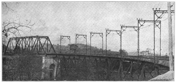
The track is well ballasted throughout with crushed rock, there being on an average 2500 cu. yd. per mile. There are 65 miles of single track and at the Pittsburg end of the road there are 11½ miles of double track. The bridges, which are numerous, are all of a very substantial construction.
| |||
| Pittsburg 1200-Volt Line — Interior of Shenango Substation |
The 80-lb. T-rails are bonded under the fishplates with twin terminal welded bonds of No. 0000 capacity. The gage of the track is 5 ft. 2 1-2 in., which conforms with that of the Pittsburg city railways over which the cars operate. The maximum grade is 8 per cent. This occurs in the city of Butler, and there are other grades of 5 per cent on the interurban section, the country traversed being very hilly. The outer rails are super-elevated on all curves to permit high speeds. There are six turn-outs which constitute the crossing points between New Castle and Butler.
TELEPHONE SYSTEM
There is a complete telephone system installed, instruments are carried on each car, and jack boxes are provided at each crossover and at distances of about one-half a mile along the track. The telephone wires are supported on the same poles that carry the trolley wire.
The car house is situated at Harmony Junction and the same building houses the offices of the superintendent and operating force of the road. It is well provided with machinery for the installation and up-keep of the car equipments. Shelters are situated at nearly all of the scheduled stops; the depot at Ellwood City is illustrated.

