[Trade Journal]
Publication: Electric Railway Journal
New York, NY, United States
vol. 33, no. 2, p. 59-62, col. 1-2
HIGH-TENSION CURRENT COLLECTION-SOME RESULTS
OF THE SWEDISH ELECTRIC RAILWAY TESTS
BY OTIS ALLEN KENYON
A great deal of attention has been given to the subject of the collection of high-tension currents from an over-head wire at high speeds on the Continent of Europe. As the readers of this paper know, many of the electric rail-ways in Europe have long used the sliding bow instead of the trolley wheel. Hence, when the single-phase system became a commercial possibility it was natural that the sliding contact should be given special consideration by the German contractors who were familiar with the use of the system for tramway purposes. During the recent tests on single-phase railway operation, conducted by Robert Dahlander under the auspices of the Swedish Government special attention was given to the subject of the best design of overhead conductors and collectors for high-speed single-phase railway operation. The results of these tests are now available through the publication of a voluminous report by the engineers in charge of the work. This report is available now in printed form only in Swedish, but the early publication of an edition in German is announced, and it is quite possible that it will be translated into English. The following notes on recent European practice in over-head construction and current collection are based largely upon this report, but are amplified by data on the same subject from other sources.
Types of overhead construction can be divided into two classes according to the method of suspending the contact wire, thus:
1. Direct suspension by span wires, brackets or bridges.
2. Suspension from messenger wire or wires by hangers placed at short intervals.
Various types of both these classes were thoroughly tested by the Swedish Electric Railway Test Commission, and a new type of the first class, or direct suspension, was developed which, according to the report, is considered best adapted to the needs of the Swedish railways. The three most important points to be considered in overhead construction are: insulation, operating performance and cost.
INSULATION
So far as insulation is concerned, the second class of overhead suspension mentioned above, the catenary, has fewer points of support than the ordinary span, bracket or bridge construction, and therefore requires fewer insulators. Other things being equal, the chances of breakdown due to defects in insulators are directly proportional to the number of insulators.
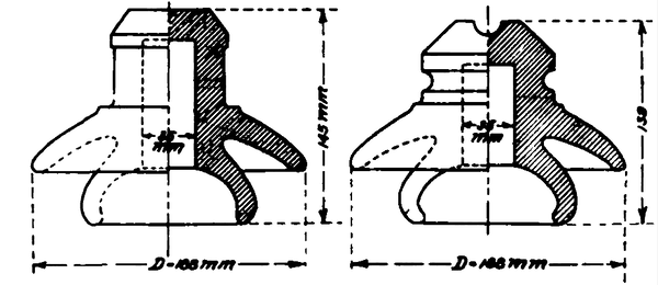 |
| Fig. 1. — Insulators Used for Trolley Suspension |
In the tests of the Swedish commission, the voltage on the contact wire varied from 5000 to 20,000, and the average working voltage was from 12,000 to 13,000. The results indicate that either class of overhead system can be satisfactorily insulated for these voltages. The weakest point in both systems seems to be the insulation of the collector. It was here that breakdowns invariably occurred when the highest voltages were tried in the Swedish tests. The commission recommended 15,000 volts as a conservative choice for the Swedish railways.
As regards the insulators themselves the commission found that, all things considered, brown-colored porcelain was the best material. Among other patent insulators, ambroin was tried out and, although it was mechanically stronger than porcelain, it was found that both its dielectric strength and insulation resistance decreased with exposure to the weather. It also costs from 50 to 100 per cent more than porcelain.
A great many shapes of insulators were tried, the most successful being those shown in Fig. 1. The form shown at the left in the diagram is intended for use where fixtures are to be clamped around the top of the insulator. The petticoats are designed to prevent the clogging of the space between them with soot and dirt.
Experiments were also tried with the Oerlikon system of overhead construction, but the report states that it is not very satisfactory on a high-speed road where there are many crossings, bridges, tunnels, etc. In the open where the collector can run along on top of the contact wire the system has the advantage of being cheap to install and easy to repair. With the Oerlikon construction, also, it is easy to have two independent contact wires, one on each side of the track. The troubles experienced with this system are all due to the necessity of bringing the wire from alongside to a position over the middle of the track. The transition must be smooth and requires that supports of special design be placed at short intervals, thus increasing the cost and reducing the reliability. Then again, the effect of highspeed is to extend the zones on each side of the crossing where this complicated construction is required, since the change in position of the collector must not be made too suddenly. The Swedish report also states that the Oerlikon overhead line is difficult to insulate properly. Though the section used in the Swedish tests was built for 15,000 volts, it could not be operated satisfactorily above 6000 volts.
OPERATION
Both classes of overhead construction operated satisfactorily at low speeds, but the first class, that is, the span construction, ceases to operate well when the speed exceeds70 km per hour (approximately 45 m.p.h.). As the speed increases the spans must be shortened until a point is reached where it is better to use the catenary form of construction. The shortest span which it is practicable to use on straight track seems to be 30 m (or approximately 100ft.).
Tension in the contact wire must be kept within a certain range or trouble will result. In cold weather the wire is liable to break and in warm weather it may become so slack as to render the operation of the collector impossible. Experiment showed that unless some automatic device formaintaining a constant tension was installed, the tension had to be adjusted once or twice a year. The proper operation of the collector required that the tension in the contact wire exceed 4 kg per square millimeter (or 5700 lb. per square inch).
Fig. 2 shows the type of construction recommended by the commission for operation at 15,000 volts and average speeds of about 40 m.p.h. There are two lines of poles, one on each side of the track, and each line of poles carries a separate single-phase feeder. Except on curves the trolley spans are 30 m (about 100 ft.) in length, thus making the feeder spans 60 m. The brackets which carry the contact wire are movable about their point of attachment to the pole and the ends of the contact wire are loaded with weights which thus maintain a constant tension in the wire. In case an insulator breaks, the bracket can be swung around out of the way and repaired and the wire will automatically pull up so that trains can pass at reduced speed. In station yards where it is desirable to reduce the number of poles to a minimum, the type of construction shown in Fig. 3 is used. Here the poles are staggered at intervals of 60m and a guy wire run from the center of the span to the top of each pole.
COST
The catenary or second class of overhead construction, while more expensive to build, is more substantial than the span wire construction and, having fewer supports to be insulated, should be more reliable and cheaper to maintain. For speeds above 50 m.p.h. the catenary type of construction must be used regardless of the cost of installation if smooth operation of the collectors is to be obtained.
The Swedish commission decided in favor of the first class of construction of the type described above, because of its simplicity and low cost.
COLLECTORS
The successful operation of any system depends upon the ability of the collector to keep in contact with the wire. Failure to do this produces arcing and hammering. The arcing destroys both the collector shoe and the wire, while the hammering accelerates the wear, kinks the wire and breaks the fastenings. The difficulty of keeping the collector in contact with the wire increases very rapidly with the speed, and the minimizing of this difficulty is one of the important problems in high-speed operation.
The variations in the position of the wire over the track, and the swaying of the car require the collecting device to be so construed as to adapt itself to all such variations, thus forming a flexible connection between the wire and the car. At low speeds it is comparatively easy to design such a device, since all variations in position take place so slowly that the inertia of the collector does not prevent it from following the wire. However, at high speeds the effect of every little variation is exaggerated and tends to produce vibration. Large variations in position, such as are caused by passing under bridges, etc., when made gradually, have little or no effect on vibration. The three principal causes of vibration are:
(1) Unevenness of the contact wire, due either to imperfect suspension or non-uniform wear
(2) Vibration and swaying of the car or locomotive.
(3) Inertia of the contact device.
Unevenness of the contact wire due to the the sagging between the supports, as explained, can be reduced to a minimum by use of the catenary type of suspension. The non-uniformity of the wear is more an effect than a cause. It is produced by the action of non-homogeneous material, arcing and non-uniform pressure on the contact wire.
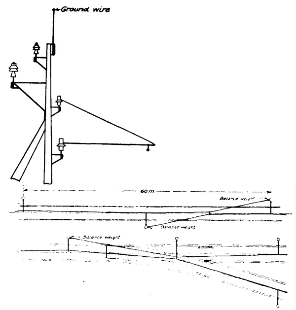 |
| Fig. 2. — Overhead Line Construction With Double Line of Poles for Feeders |
The vibration and swaying of the car can be reduced to a minimum by careful ballasting of the track. Further-more, in cases where very high speeds are reached, the cars themselves may be balanced. In the Berlin-Zossen tests, where the cars attained speeds of 130 m.p.h., it was found absolutely necessary to balance the cars in order to keep them on the track. At high speeds, however, vibration and swaying of the cars cannot be entirely avoided, and no matter how well the wire is suspended, it cannot be made absolutely parallel to the plane of the track. The collecting device must follow these variations of car and wire if it is to remain in contact, otherwise there will be arcing which will destroy the contact surface, and hammering of the wire which will produce non-uniform wear of the wire. Both of these causes still further exaggerates the trouble. If the collector is to operate with perfect satisfaction, the natural period of vibration of the part that carries the contact shoe must be greater than the highest vibration which it will be called upon to make.
The experience of the New York, New Haven & Hartford Railroad, as given by W. S. Murray in his last paper before the American Institute of Electrical Engineers, illustrates this point and shows the disastrous effect of at-tempting to collect current at high speed by a heavy contact device with low natural period of vibration. The method followed by the New Haven road to reduce the trouble consisted in rigidly suspending by clamps an auxiliary steel wire from the old copper conductor. That this expedient has not been a perfect remedy is shown by the statement in Mr. Murray's paper that probably even better results could be obtained by suspending the auxiliary wire by loops instead of rigidly from the copper conductor.
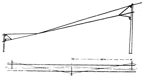 |
| Fig. 3. — Overhead Line Construction With One Half the Usual Number of Poles |
In appearance, the New Haven auxiliary wire construction is very similar to the type of construction installed some years ago by the Siemens-Schuckert Company on the Hamburg-Blankenese road, and described in the STREET RAILWAY JOURNAL for April 6, 1907. However, it is quite different in principle. On account of its rigid construction the practical benefit of the introduction of the steel wire on the New Haven road is limited to that which results from substituting for copper a metal that can stand the treatment administered to the contact wire by the collector, there being no gain in the flexibility in the construction other than that due to the character of the metal itself. The Siemens-Schuckert system does not employ a steel wire but one of hard copper, the purpose of the auxiliary wire being solely to reduce vibration. The whole secret of the improvement lies in the use of a special clamp, which allows a longitudinal and vertical movement of the contact wire of the kind recommended by Mr. Murray as advisable. The tension in the contact wire is adjustable and is automatically maintained constant by balance weights.
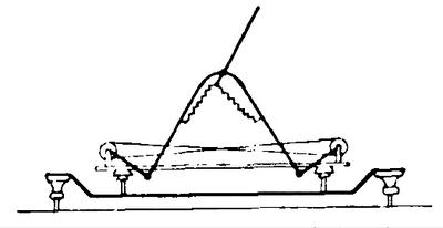
The principal types of sliding contact collectors used in Europe are shown schematically in Figs. 4 to 9.
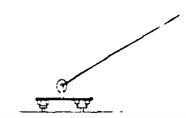 |
| Fig. 4. — Plain Bow Collector |
 |
| Fig. 5. — Siemens-Schuckert Collector for Swedish Tests |
Fig. 4 shows the plain bow trolley employed on the direct-current street railway systems. It can be used for high tension when mounted on porcelain insulators. The arm is balanced by springs so disposed as to exert a uniform pressure of about 5 kg (11 lb.) against the wire, in-dependent of the angular position. The arm is long and therefore the natural vibration period of this system is low. In the Swedish tests it was found entirely unsuited to speeds above 25 km per hour ( 15 m.p.h.).
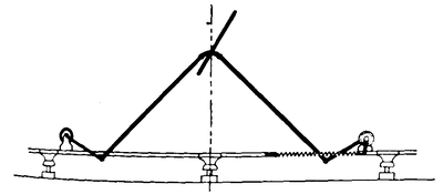
The Siemens-Schuckert Company designed the type shown in Fig. 5, which was tried out during the railway tests in Sweden. This device consists of two parts : the main body, which is hinged to the stand in such a way as to take care of the large variations in height of the wire, and the upper piece, which carries the shoe and is hinged to the lower part. The upper part is about 80 cm (32 in.) long, and although the construction is very light, the length is such as to give it a natural period of vibration which limits the speed at which it will work satisfactorily. The report of the Swedish tests, however, does not specify the exact limitations of this type except that the bearing friction was found to be great and the balancing springs complicated as compared with other types tested. The same company built a similar device shown in Fig. 6, which is in use on the Hamburg-Blankenese road.
 |
| Fig. 6. — Siemens-Schuckert Collector for Hamburg-Blankenese Line |
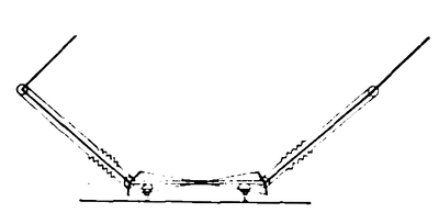
Fig . 7 shows a type which is a modification of the design of Brown, Boveri & Company used on the Simplon locomotive. This form was developed by the Allmänna Svenska Elektriska Actiebolaget in consultation with the engineers of the Swedish State Railways. The device consists of two long arms so interconnected as to balance the wind pressure and exert a uniform pressure against the wire, as are all the modern types. The upper part, which is supposed to follow the variations of small amplitude, is pivoted to the end of the long arm and is equipped with stops in such a way that the rear upper contact arm cannot be deflected backward more than 30 deg.; this guards against the possibility of the forward bow refusing to lower at points where the wire descends into tunnels, under bridges, etc. If the front top bow gets stuck in one position the rear bow, not being able to bend backward more than 30 deg., will depress the front bow through the cross connections. This requires a rather long upper bow (80 cm), and therefore, as far as inertia goes, it has the same limitations as the design shown in Fig. 5.
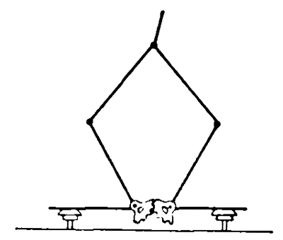
The pantograph bow as designed by the Allgemeine Elektricitäts Gesellschaft is shown in Fig. 8, and like practically all of the other collectors built by European manufacturers, consists of two parts, one being a trailing col-lector. The pantograph or lower part takes up all the great variations in height of the wire, while the upper arm, which is very light and only 30 cm high, takes up the slight variations. This upper arm has a comparatively high natural period and therefore works very satisfactorily. In the Swedish railway tests, a simple aluminum contact shoe gave perfect satisfaction with this type of collector.
 |
| Fig. 7. — Collector Designed for Swedish Test |
The side rod contact system, developed by the Oerlikon Company, has been described at various times in the pages of this journal. It is a very radical departure from the usual form and, as explained, involves considerable difficulty in the line construction and the operation at cross-overs, tunnels and bridges where the contact wire must be gradually brought up from a position alongside to a point over the car. This system was installed on one section of the test tracks in Sweden and tried at moderate speeds (45 m.p.h.) and with 6000 volts on the contact wire. The special overhead construction required, like all types of direct suspension, is not suitable for high-speed work, although on straight track in open country the collector seems to follow the wire with but slight sparking at the supports. The principal disadvantages pointed out in the report of the Swedish commission are: Short distance of the high-tension contact wires over the track in stations, due to the necessity of keeping the pivot of the collector rod inside the clearance limits; complication and cost of overhead construction under bridges, in station yards, at crossings, etc.; liability of the collector rod catching in the contact wire at crossovers and switches, and poor contact on curves taken at speed when the wire is on the inside, due to centrifugal force lifting the rod and causing it to vibrate against the wire, producing vicious sparking.
CONTACT SHOE
The wear of the contact shoe does not mean much unless the wear of the contact wire is also known. However, if aluminum or some soft alloy is used it is fair to assume the wear of the contact wire is negligible compared with that of the shoe. Siemens & Halske build a shoe that is U-shaped in section, the inside being filled with a hard grease. This reduces the wear and also the singing, which is some-times objectionable.
 |
| Fig. 8. — Pantograph Bow Collector |
Wear of the wire and shoe can be traced to two causes, mechanical and electrical. The mechanical causes are due to pressure and cannot be entirely eliminated. Non-uniformity of pressure is the most serious trouble. The springs can be so designed as to make the pressure constant for any position of the collector. However, the speed at which the collector changes its position affects the pressure to an extent which can only be controlled by reducing the inertia of the mass to be moved. Throughout Europe the average pressure of the contact shoe against the wire is about 5 kg (11 lb.). An exception to this practice is the Oerlikon collector, which exerts only 0.7 kg (1.5 lb.). This low pressure is necessary on account of the great length and lightness of the rod. A greater pressure would necessitate a heavier rod and introduce greater inertia.
The electrical causes are secondary, being due to arcing, which is caused by insufficient contact surface. Arcing is especially destructive in that once started the surface is left more predisposed to arcing than before and conditions rapidly go from bad to worse. The cause is due to imperfect contact and vibration and the resulting wear is a function of the current rather than of the power. For a given power the lighter the voltage the less destructive is the arc. Soot deposited on the contact wire by steam locomotives increases the wear to an astounding extent. The Swedish commission found that the wear of the shoe on a soot-covered wire is about 10 times as rapid as on a clean one. In these tests the Oerlikon collector wore out at an extremely rapid rate. The rod was of brass 9mmin diameter, and had to be removed after traveling between 200 and 400 km. The aluminum shoes on the other types of collectors ran about 2500 km (1500 miles on soot-covered wires. It is estimated in the report that on clean wires they would run at least 20,000 km (12,500 miles). The practice of the Swedish tramways indicates an average life of such shoes, when used in tramway service, of 20,000 km (12,500 miles) before renewal, but if left until worn out they will run as high as 100,000 km (62,000 miles).
CONCLUSIONS
The results of experiments made thus far seem to point to a type of collector which should consist of two parts, namely, a main part to take up the large variations in the height of the wire and an auxiliary part to take up the vibrations. The main part may be comparatively large and heavy and should be balanced for wind pressure and provided with springs arranged to exert a constant pressure irrespective of the position of the shoe. The auxiliary part, which should trail, must be light and designed to have ahigh natural period of vibration which will enable it to follow the most rapid vibrations of the car to which it will be subjected.
