[Trade Journal]
Publication: Proceedings of the American Institute Of Electrical Engineers
New York, NY, United States
vol. 28, no. 3, p. 7-19, col. 1-2
Notes on Transmission Practice
in the Northwest
BY MAGNUS T. CRAWFORD
The object of this paper is to assemble in a form convenient for comparison and discussion the various systems of high-tension transmission in the Northwest, and to discuss the relative merits and defects of each system. As each section of the country has its own characteristic set of climatic and industrial conditions, transmission practice features that are economical and good practice in one section may be more or less unsuitable in another section. For this reason this discussion will be confined to practice in the Pacific Northwest. As typical examples, a number of systems will first be briefly described, and discussed in detail later.
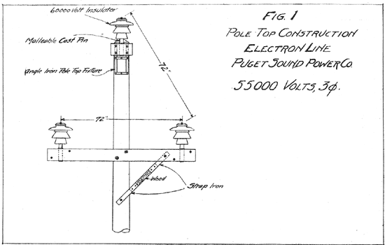 |
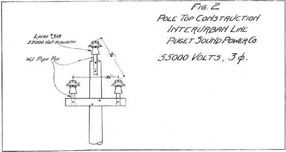
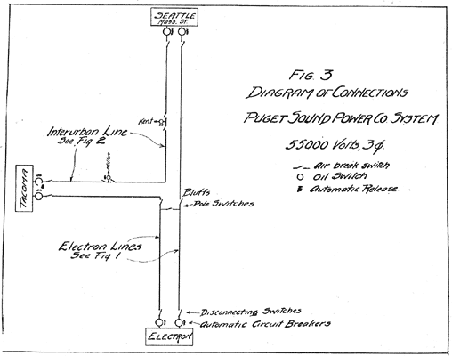
Puget Sound Power Company. This company operates a hydroelectric station at Electron, Washington, on the Puyallup River. Two 55,000-volt, three-phase lines run parallel to Bluffs, where they separate; one goes to Tacoma, the other to Seattle, following the Puget Sound electric railway right-of-way. These lines were built in 1903 and have the construction shown in Fig. 1. The wire is 0000 B. & S., 19-strand, semi-hard-drawn copper, except from Bluffs to Tacoma, where it is 0 B. & S. solid copper. The insulators are standard four-piece, 60,000-volt porcelain on galvanized malleable cast-iron pins of a design similar to a pipe pin. Part of this line was equipped with wooden pins for trial, but the iron pins have proved more satisfactory. The length of the Seattle line is about 50 miles, that of the Tacoma line about 30 miles. At the generating and substations each line is controlled by a switchboard panel equipped with three ammeters, one automatic, remote-control, oil circuit-breaker, and one overload time-limit relay. The circuit-breakers are electrically operated oil-switches in concrete compartments. At Bluffs disconnecting pole-switches are used for paralleling and cross-connecting the lines, as shown in Fig. 3. A second line of solid copper, known as the interurban line, runs parallel and on the opposite side of the railway, feeding into sub-stations located at Massachusetts street, Seattle, and at Kent, Milton and Tacoma. The size of the wire is 1 B. & S. solid copper from Seattle to Georgetown, 4 B. & S. from Georgetown to Milton, and 1 B. & S. from Milton to Tacoma. This line is constructed as shown in Fig. 2, and has been operated at 55,000 volts for the last few months. It was originally built for this voltage, but until recently has been operated at 30,000 volts. Although the spacing between wires is rather small, no trouble has been encountered, as the spans are not over 100 ft.
 |
 |
This company reports practically no trouble from electrical failures of insulators on either line, as all insulators were tested before they were accepted. The only trouble has been from softening and burning of wooden pins. These pins have been replaced by wrought-iron pipe pins, and no difficulty has arisen since.
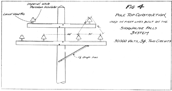
Seattle-Tacoma Power Company, Snoqualmie Falls System. The system of this company has been in operation for 10 years, and is the oldest high-tension transmission system on Puget Sound. Some of the apparatus installed is of a type now obsolete, but the plant is being gradually rebuilt, and much of it is new and modern. The main generating station is at Snoqualmie Falls. As originally built this system consisted of a double-pole line from Snoqualmie Falls to Renton, and single-pole lines from Renton to Tacoma and from Renton to Seattle. Each pole-line carried two three-phase, three-wire, 30,000-volt circuits arranged as shown in Fig. 4, with a space of 30 in. between the wires. The wires were of aluminum with a cross-section of approximately 65,000 cir. mils. The insulators were triple petticoat imperial porcelain of the Redlands type. After a few years' operation, this system was rebuilt with larger wires and a larger space between them. Various difficulties were encountered with the 30-in. spacinglarge birds, sticks, bale-wire, etc., became entangled in the wires, causing short-circuits. A wire once burned off was apt to whip around and short-circuit the others as well.
 |
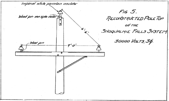 |
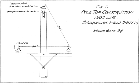
In 1903 the lines were reconstructed with only one circuit per pole line, giving a 9-ft. by 6.5 ft. fiat triangular spacing as shown in Fig. 5, by simply removing the top cross-arm and putting on a pole-top pin. A new pole-line was built from Renton to Tacoma and one from Renton to Seattle, with a 7-ft. triangular spacing as shown in Fig. 6. The same insulators were used, as they had proved satisfactory. This gave two separate pole lines from Renton to both Seattle and Tacoma. On these lines a seven-strand aluminum cable of 00 B. & S. gauge was used, and from Renton to the falls each line was of seven-strand aluminum 0000 B. &. S. gauge. The reconstructed system has now been in operation about five years, and the wide spacing has given almost entire freedom from trouble due to short-circuits between the wires. As shown on the sketch, the insulator pins are of locust wood. About a year ago these pins began to give trouble from burning and softening. They were replaced on curves and important points by malleable cast-iron pins.
 |
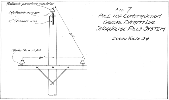 |
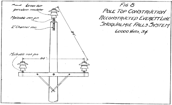
In 1906 this company built a single pole-line from Snoqualmie Falls to Everett, with the construction shown in Fig. 7. The line was of No. 4 medium-hard-drawn copper, and the insulator of shape similar to the imperial white insulator on the main lines, but made of brown porcelain. Malleable-iron pins were used throughout, being fastened to a channel at the pole-top as shown. The porcelain was not of so good a quality as that in the imperial white insulators, and occasional trouble resulted from insulators shooting through the head to the pin when a ground came on the system. In 1908 this line was reconstructed for 60,000 volts in order to carry the increased load, and as the first step in the change of the entire system to 60,000 volts. The new construction is shown in Fig. 8. There has been no trouble of any nature, though the line has been in service several months.
 |
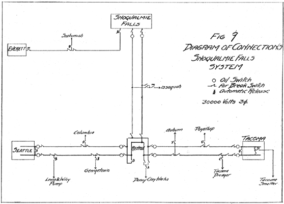
The general switching arrangement is shown in Fig. 9. There is no automatic release anywhere on main lines, as this company believes such apparatus to be a hindrance rather than a help. This will be discussed more fully later. The switches used at the falls are non-automatic oil switches in compartments. Those at Renton, Seattle, and Tacoma are tank switches, consisting of a double-break switch immersed in a separate tank of oil for each leg of the line. They are controlled manually by an arrangement of levers. This company has never had any trouble from high-tension oil switches, although they have been used to open some severe short-circuits. On outside lines a disconnecting pole-switch is used. For branch lines a horn-fuse is also used, either on a pole or on a bracket fixture on the outside of the station wall. Small sub-stations are equipped with an air-break fuse inside the station.
 |
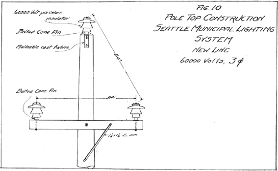
Seattle Municipal Power Plant. At present this system consists of one 30,000-volt transmission line connecting the generating station on Cedar River with the sub-station in Seattle. This line is of the same construction as that in Fig. 6, except that a three-petticoat, two-piece, 45,000-volt insulator is used. The pins are of eucalyptus wood boiled in oil; the wire is No. 2 solid copper with a 7-ft. spacing. This line was built in 1904, and has given virtually no trouble from electrical failures of insulators or burning of pins. It is controlled by air-break disconnecting switches on the high-tension side, an automatic release being on the 2000-volt side of the transformers at the generating station. A new line now nearing completion has a construction shown in Fig. 10. The line wire is 0000 B. & S. seven-strand copper, and the operating voltage is to be 60,000 volts. Spans are from 400 to 450 ft. on the straight way. This is a radical departure from the present lines on Puget Sound, but represents the most recent practice in transmission. The old line is to be changed to 60,000 volts and the two lines will then be operated in multiple, with automatic oil switches on each line actuated by overload and reverse-current relays.
 |
Several months ago an attempt was made to operate the old line at 55,000 volts, the transformers being changed from delta to star connection. No difficulty was experienced in dry weather, but in wet weather so much trouble ensued that it was necessary to change back to the old voltage. The high voltage gave trouble by heavy leakage currents setting fire to the wooden pins. No trouble was experienced from electrical failure of the insulators during this time; there should have been no trouble, as the manufacturer's test on this type of insulator is 100,000 volts.
Whatcom County Railway and Light Company. Nooksack Falls System. This company has a hydroelectric generating station at Nooksack Falls, and supplies power to the city of Bellingham over a single transmission line. This line is built for 60,000 volts, but at present it is operated at 22,000 volts from delta-connected transformers. The length of line is 40 miles; the wire is 0 B. & S. seven-strand aluminum; the spans are about 150 ft. on the straightaway portion, while those at river crossings are as long as 750 ft. The pole-top construction is shown in Fig. 1, except that a pipe pin is used, doing away with the pole-top fixture. From the sub-station in Bellingham a branch line extends about 2 miles to Fairhaven, where there is a second sub-station supplying light and power to that section of the city. This branch line is connected to the main line by pole disconnecting switches. It is of the same construction as the main line with the exception of the spacing between wires, which is 5 ft. instead of 6 ft.
The only high-tension switch used on this system is a simple knife disconnecting switch. All switching under load is done on the 2000-volt side of the station transformers. Line short-circuits open the automatic circuit-breakers on the 2000-volt side at the generating station, so that to obtain uninterrupted service it would be necessary to keep the steam generating station in Bellingham on the system at all times. This station is used only in emergency at present, as very little line trouble is experienced.
Having given some of the characteristic features of representative systems in this locality, a comparative discussion may now be of value. In this I shall draw freely on the experiences of the different companies, the opinions of their engineers, and also on the opinions of representative engineers of the present day as set forth in recent papers before the American Institute of Electrical Engineers.
One of the things for which Western practice is criticized is the tendency to build lines that are cheap. Mr. F. G. Baum has said in a paper before the Institute [Trans. AIEE, 1907, Vol. 26, Part 2, page 1555]:
It may not be as difficult to determine the proper power station and line to build when unlimited capital and ideal power conditions exist as when there is restricted capital, limited revenue, and low-priced power at the consumer's end.
Mr. Baum's idea is the answer to such criticism. In the Northwest especially, the lines are very long, passing through rough country; the cost of the transmission system is a big item in the total cost; the power business is usually more or less scattered; and the revenue comparatively small. Economy must therefore be given consideration by the engineer or his designs will not be feasible, and his enterprise will not receive financial support. It requires much more thought and engineering ability to design a satisfactory line with limited expenditure than it does where the line forms a small part of the total in vestment and its first cost is comparatively unimportant. In consideration of these facts, the item of first cost will be given attention in the following discussion.
Line wire. Opinion seems divided between aluminum and copper for use in transmission at high voltages, but in general it may be said that both are satisfactory. As examples for comparison, take 0000 stranded aluminum and 00 hard-drawn solid copper. The stresses at elastic limit are taken at 15,000 and 20,000 lb. per square inch for copper and aluminum.
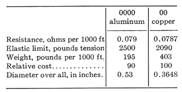 |
There are many practical drawbacks to the use of aluminum; it is difficult to make good joints, as the metal will not take solder; it is a highly electro-positive metal, and when exposed to the air in contact with other metals an electrolytic action is set up in which the moisture of the air and chemical impurities forms the electrolyte. These difficulties may be overcome by carefully made and protected joints. Aluminum has a very high coefficient of expansion with change of temperature, which is apt to be troublesome in climates having extremes of temperature. Its large diameter makes a larger surface for collection of sleet and ice and a larger resisting surface to high winds. In the Puget Sound country extreme temperatures, sleet, and very high winds are never encountered, so that aluminum is well adapted to local conditions.
The systems using it have never had any difficulty which could be charged against the metal. As seen from the above figures, it is somewhat stronger, weighs about half as much, and costs ten per cent less for copper wires of the same conductivity. Ten per cent in the line wire is a fair-size item in the line cost, and additional saving can be effected in freight and teaming in the delivery and stringing up in a rough country.
Poles and construction features. The question of poles versus towers is not considered in this part of the country, where excellent poles are obtainable on the ground and steel is expensive, although it may come in for consideration in later years. When the first lines were built in the Northwest about 10 years ago, the use of 35-ft. poles with 7-in, or 8-in. tops was considered good practice, as the spans were from 110 to 125 ft. and the wires light. Much heavier wires and insulators are now used and the spans are longer, so that the tendency is to increase the size of the poles. The new line now under construction by the municipal light and power plant in Seattle is using 55-ft. poles with 11-in. tops, on. spans of 440 ft. On the Nooksack Falls line, 45-ft. poles with 9-in. tops on spans of 150 or 200 ft. are used, which is about the same as on the 1904 lines of the Seattle-Tacoma Power Company and the city plant. It is thus apparent that the trend is toward longer spans, with fewer and more substantial supports.
The construction details of the pole-top vary considerably in the different systems. In some installations in Utah and Montana the pole-top pin is driven into a hole bored into the top of the Pole. In the wet climate of the Northwest this construction would be apt to cause rotting of the core of the pole at the top, so that the pole-top is always pointed to shed the water and the pin fastened to the side of the pole. The experience on every system using wood pins has been that after a number of years the pins are apt to soften or burn. The leakage of currents over the insulator to the pin forms nitric acid from the nitrogen in the air and the hydrogen and oxygen in the moisture, and the acid eats into the pin until the latter becomes quite pulpy. Wooden pins are usually carefully dried and boiled in paraffin or linseed oil, but even then they will begin to soften and burn in from 5 to 10 years, depending on the line voltage. The Seattle municipal plant had a great deal of trouble a few months ago from charring and burning of wooden pins at the point of contact with the insulators, during the time that they were running 55,000 volts on their 45,000-volt line. In this case the leakage currents were so heavy that a high temperature was produced at the threads of the pin, due to the ohmic resistance to the passage of the current at this point. At the lower part of the pin and on the cross-arm there was not so much burning, due probably to the accumulation of dirt and organic matter, and to the fact that the large wet surface offered a lower resistance.
Iron pins give entire freedom from such troubles, and also provide the strength necessary for long spans and heavy wires. There are several types of iron pins now in use. The simplest is what is known as the pipe pin, consisting usually of a short length of 2-in. extra-heavy wrought-iron pipe swaged down at one end and cemented in the insulator. Another type consists of a cast-iron cone with a steel bolt up through the centre and screwing into a nipple which is cemented in the insulator. This type is used on the new city line. A third type consists of one solid malleable-iron casting with tapering cross-ribs above the cross-arm and a round pipe shank or a bolt extending through the cross-arm. This is held down by a through bolt or a bolt underneath the cross-arm, and may be threaded and screwed into the insulator. The Northern Colorado Power Company has a pin of this type held down by a U-bolt extending around the outside of the arm. These are the three general types of iron pins now in use in the Northwest. The pipe pin costs from 55 to 60 cents, the bolted cone pin about 50 cents, and the malleable cast-iron pin from 20 to 40 cents depending on the design. The pipe pin has the great advantage of simplicity and absence of bolted parts, and requires no pole-top fixture; but on the other hand it requires at least a 2.5 in. hole in the cross-arm, which necessitates a larger arm. As the insulator must be cemented on the pin, it is necessary to change the pin as well whenever an insulator is broken. With the bolted cone pin only a 5/8-in. hole in the cross-arm is good quality and free from cracks or pits. On the Snoqualmie system two different insulators of almost exactly the same shape are used-white imperial porcelain on the main lines and chocolate colored porcelain insulators on the Everett line, The porcelain in the latter was not quite so good as used in the white insulators, and they would not hold up under so high a voltage, even though they were of the same design. The fracture of high-grade porcelain shows a vitreous and almost polished surface. The glaze possesses no insulating value, but is simply to prevent the adherence of dust and dirt, and hence it should cover the entire outer surface. High-tension porcelain should be thoroughly vitrified and nonabsorbent. A test for porosity is obtained by soaking the porcelain in ink; if non-absorbent the ink should be easily washed off with water.
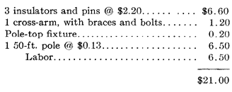
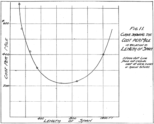
Spans. The subject of spans in transmission lines has been given considerable attention by engineers in the last few years. During the early days of high-voltage work short spans were thought necessary in order to insure against breakage of wires, and as the wires were usually small and the spacing between them not over a few feet, long spans would have given trouble. It has been found, however, that wires never break of their own accord if properly strung and if all kinks are replaced by splices, and that if a spacing of 6 or 7 ft. is used there is no danger of the wires swinging together. Large wire having great tensile strength is now used and long spans are operated with safety. The weak point in a transmission line is its point of support, and anything which reduces the number of supports decreases the number of weak points and also the loss from leakage. The great advantage lies in the reduced cost. This reduction in cost, however, will not hold if the length of span is made too great, as it then becomes necessary to build expensive towers and heavy construction in order to take the strain safely. In order to determine the most economical length of span, the procedure outlined by D. R. Scholes [Transactions AIEE, 1907, vol. 26, part 2, page 1221.] is the simplest and may be applied to wood poles as well as to steel towers. A curve is plotted with cost per mile and length of spans as coordinates. As an example let us assume a 55,000-volt line. With spans of 100 to 150 ft., a 5-ft. spacing between wires is good practice. A light, malleable cast-iron pin, 4-in. by 6-in. cross-arms, and 40-ft. poles with 8-in. tops would be used. The labor of setting and framing the pole will vary considerably with the locality, but may be estimated at .00. We then have the cost per pole:
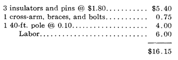 |
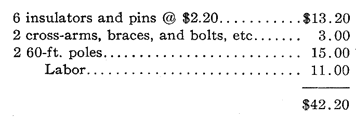
With 35 poles per mile (150-ft. spans) this comes to 5.25 per mile, and with 45 poles (118-ft. spans) 6.75 per mile. For spans of 250 to 500 ft. a heavier construction is needed, with a spacing of at least 7 ft., between wires, similar to the new line of the municipal plant in Seattle. At least 50-ft. poles with 10 in. tops are needed, with 5 in. by 7-in. cross-arms. A substantial design of pin is needed, well fastened to the cross-arms. Taking a design similar to that on the city line:
 |
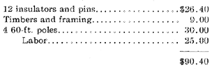
With 20 poles per mile (260-ft. spans) the cost will be 0.00 per mile, and with 15 poles (350-ft. spans) 5.00 per mile. This construction if carefully designed can be used up to 500 or 600 ft. Although single poles are used for spans up to 900 ft. in California, the opinion here seems to be that with spans over 700 ft. an A-frame should be used with double construction. The cost of this may be estimated at:
 |
With 6 poles to the mile (860 ft. spans) the cost will be 3.20. If the line has many bad curves this figure will be considerably increased. With spans over 1000 ft., a 4-pole tower is recommended. This will cost:
 |
With 1200-ft. spans the cost will run up to 0.00 per mile, which is past the economical point, as seen on the curve in Fig. 11. These figures are only approximate, and are given chiefly to illustrate the principle involved. The influence of curves, character of country, etc., may make long spans impossible in some parts of the line, which will make the most economical span shorter. On the other hand, a mountainous country affords excellent opportunity for spans from hill-top to hill-top, making a large saving in clearing trees on the right-of-way, etc. Each particular line must be worked out with reference to the local conditions.
 |
Switching and operation. Some diversity of opinion exists as to the best scheme of switching. The Electron system with two 0000 copper lines and 55,000 volts uses automatic circuit-breakers at each end of its transmission lines, and normally these lines are not connected in multiple on the high-tension side. A short-circuit on the system which lasts only a few seconds will not open the breakers, as the latter are protected by relays; but a short-circuit which holds on will open the line at Electron and also at the sub-station in order to prevent feeding back into the short-circuited lines. The Snoqualmie system with two 0000 aluminum lines at 30,000 volts has no automatic release on its high-tension lines, except where small sub-stations or branch lines tap the main system, and on the switches used for connecting the lines in multiple. A short-circuit coming on either line usually releases the multiplying switches. The operator at the falls can then usually see from the line ammeters which line the short-circuit is on, and opens that line with the oil-switch, if for any reason it is not apparent which line is in trouble, the voltage is lowered and the short circuit is "pulled" until it is burned off, but both lines are never cut out. Automatic circuit breakers are used between the steam generating station in Seattle and the transmission system so that the steam plant will not feed back into the short-circuited high-tension line. This non-automatic method of operation has given excellent results on this system, as most of the line short-circuits can be burned off within one or two minutes at the most, and the only effect at the sub-stations is a bad dip in the voltage. This is much better than shutting down for the five or ten minutes necessary to switch out the bad line, as all synchronous apparatus is then thrown out and must be started up and synchronized all over again. Long lines with comparatively small wires are more easily handled in this way. With a short line, high voltage, and very heavy copper a surge may occur with a bad short-circuit which will have a destructive effect on the windings of the generators unless their impedance is high. This country is rapidly developing, and within a few years much heavier capacity lines and higher voltages will be employed, and a more complex system with a number of stations tied together will result. More or less automatic apparatus will then become necessary. The plans of the new Seattle municipal system shows the best practice for automatic line protection. They expect to use both overload and reverse-current relays in connection with automatic circuit-breakers. Unless they are well made, and judgment and care used in their installation and use, the relays may not give satisfaction. The primary object of the relay is to control the automatic release of the circuit-breakers. The ordinary overload relay may be set for a certain time limit, and if the overload continues for that time the relay will trip the breaker. If a heavy short-circuit comes on the line when there are only a few generators in service, the voltage may be pulled down too low to operate the relay, and the design must be such as to insure operation at very low voltages and power-factors. Reverse-current relays are used at the sub-station end of the line to prevent feeding power back into the defective line where two lines are operated in multiple. Relays should open the short-circuited line at each end quickly enough to prevent synchronous apparatus on the system from falling out of step; but at the same time they should not operate at slight surges caused by an operator making a slight miss in synchronizing. During the synchronizing of generators at Electron, it is the practice to cut out the relay on the generator circuit-breaker so that a bad throw will trip out the incoming machine instantly without disturbing the system. The general conclusion to be drawn from switching practice in the Northwest is that non-automatic operation is satisfactory, and will give good results on systems where the line conductors are not too large and the voltage not over 50,000 volts. In very large and complex systems handling large amounts of power at short distances, automatic protection becomes necessary.
