[Trade Journal]
Publication: Elektrotechnische Zeitschrift
Berlin, Germany
p. 632-635, col. 1-3
About hanging and tension insulators.
By Dipl.-Ing. W. Weicker, Hermsdorf, S.-A.
(End of p. 600.)
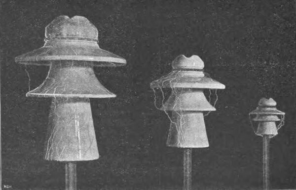
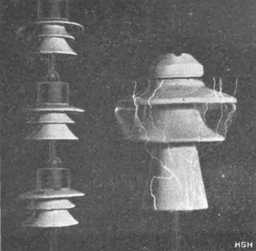
As far as the fundamental importance of the use of several hanging insulators connected in series or general multiple insulators¹) compared to a single (support) insulator in electrical terms is concerned, it should first be pointed out that with a support insulator of the usual design, the discharge phenomena change in an extremely unfavorable way when a certain voltage limit is exceeded: the larger a support insulator becomes, the more the sliding of the spark discharges, which is hardly noticeable on small insulators, becomes apparent. Fig. 17 may show this first of all on three insulators of different sizes, 12, 25 and 39 cm in diameter and 12, 32 and 49 cm high: In the smallest insulator, the spark discharges occurred without touching the sleeve, from the lead wire directly to the support, in the middle insulator, the sparks first hit the elongated sleeve in order to slide along it, and finally in the largest insulator, in the manner of the known sliding sparks on plates and tubes backed with tin foil, extremely finely branched sliding bushes appeared, which open the path for the following spark. As a result, the spark hardly jumps over the air gaps in between, but mostly follows the surface of the individual porcelain surfaces. This is a phenomenon that is characteristic of all insulators of any shape of a certain size that have a
| |||
| Fig. 17. Support Insulators of Different Sizes Under Voltage to Illustrate the Different Types of Discharge |
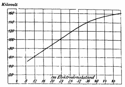 |
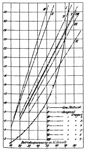
| Fig. 18. Dependence of Spark Voltage on the Flashover Distance on Porcelain Insulators of Different Sizes. |
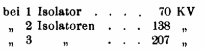
wide-reaching support and a long sleeve. If the voltage measured for sparking is plotted as a function of the arcing distance between the conductor wire and the support, the curve shown in Fig. 18 is generally obtained, according to which the arcing voltage increases only slightly for very large arcing distances. This can be explained by the fact that the arcing distance for pure creeping spark formation increases approximately with the third to fourth power of the voltage and that a large post insulator of the usual design represents, in terms of its shape, a combination of spark discharges in the air and creeping sparks along porcelain surfaces. As a result, the use of extremely large post insulators is necessary for high operating voltages. The significant increase in weight resulting from this can be illustrated by the following small compilation, which shows the weights of the curves ordered for certain conductors, according to which the arcing voltage increases only slightly for very large arcing distances. This can be explained by the fact that the arcing distance for pure creeping spark formation increases approximately with the third to fourth power of the voltage and a large post insulator of the usual design represents, in terms of its shape, a combination of spark discharges in the air and creeping sparks along porcelain surfaces. As a result, the use of extraordinarily large post insulators is necessary for high operating voltages. The significant increase in weight resulting from this can be illustrated by the following small compilation, which shows the weights of the porcelain insulators of one and the same type required for certain operating voltages from the Hermsdorf Porcelain Factory, S.-A.:
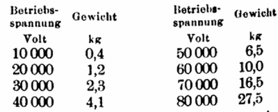 |
Both this extraordinary increase in weight and the associated increase in price (above about 50,000 V operating voltage, the weight of a support insulator increases almost to the third, even higher, power of the operating voltage) make the use of individual support insulators above voltages of about 70,000 V extremely uneconomical, if not impossible. In contrast, breaking down an insulator into individual parts connected in series offers the possibility of an almost unlimited increase in voltage; because, as will be shown below, the total spark voltage can be assumed to be approximately proportional to the number of insulators connected in series. On the other hand, the weight of a group of suspended insulators also naturally only increases in a linear relationship with the number of insulators.
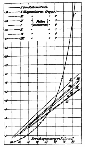 |
| Fig. 19. Weights of Post Insulators Compared to Hanging Insulators of Different Groups in Fig. 23 at the Same Operating Voltage. |
In order to illustrate the above-mentioned fundamental differences between support and hanging insulators in quantitative terms, Fig. 19 shows the weights of hanging insulators of different shapes required for a specific operating voltage, along with the weights of corresponding support insulators required for the same operating voltage, whereby the same safety factor is assumed for the operating voltage as for the support insulators. The weight of the hanging insulators includes the metal parts required to connect the individual insulators.
 |
| Fig. 20. Ratio of the Prices of Post Insulators to Those of Suspension Insulators at the Same Operating Voltage. |
A similar comparison of prices is shown in Fig. 20, based on the same conditions. In fact, for support insulators, this also includes the price of the support, as well as any necessary reinforcement of the cross arms and masts, and for hanging insulators, the additional costs caused by the height of the mast.
| |||
| Fig. 21. Comparative Test of A Post Insulator and A Group of Suspension Insulators at 130000 V. |
Nevertheless, it can be seen from both figures 19 and 20 that in this direction, hanging insulators only offer advantages over post insulators from a certain voltage (under the assumptions made above, from 60,000 to 70,000 V depending on the insulator shape): the higher the operating voltage, the more obvious the advantages of multiple insulators. To illustrate what has been said, for example, in figure 21 three hanging insulators each weighing 13 kg in total, including iron fittings, are compared with a porcelain insulator weighing 19 kg for an operating voltage of 75,000 V, whereby, as the photograph taken at 130,000 V under lateral irrigation shows, the post insulator shows discharge phenomena (particularly brush discharges) even much earlier than the hanging insulators. Only a much smaller type of hanging insulator would be equivalent to the post insulator in this respect.
Without going into the other fundamental differences and advantages of hanging insulators compared to post insulators (e.g. in terms of operational safety in the event of a part being shattered or broken through), the different types of hanging insulators can be compared below according to their behavior in rain.
In terms of safety against edge discharges, insulators designed in the style of tension insulators (Fig. 1 to 3, p. 597) are ruled out for higher voltages from the outset. Insulators according to Fig. 21 (p. 599) also behave very poorly in this respect, as a significant current transfer takes place along the surface even at very low voltages due to the lack of any protection from rain. The disc shape shown in Fig. 7 (p. 597) is somewhat more practical in this respect, but even in this case the ratio of dry surfaces to wet surfaces is quite unfavourable. The insulator shape shown in Fig. 18 (p. 599) also shows pre-discharges even at relatively low voltages, which, however, are less due to the low insulation resistance than to the formation of sliding brushes associated with the weak, smooth porcelain shards. In this respect, an insulator according to Fig. 13 (p. 598) behaves by far the most favourably, which has a very low capacity with almost unlimited breakdown safety, and in which there are almost no pre-discharges before the actual spark discharge. Only the disadvantages common to all hanging insulators with open channels and loosely guided wire ropes (risk of rust, chafing of the ropes, glow discharges between the rope and porcelain) are also unavoidable with this insulator. The designs in Fig. 9 ff. (p. 598) are in terms of their electrical behavior in the middle between the disc insulators in Fig. 7 (p. 597) and the insulator in Fig. 13 (p. 598), with which they share the rain protection of the wide sheaths. Compared to the latter insulator forms according to Fig. 8 to 11 (p. 598) with the cable guide that is still not very favorable with regard to edge discharges, the insulator design according to Fig. 16 (p. 598) has the advantage of the central electrode arrangement and a completely symmetrical field distribution. This is particularly true for the insulators equipped with a metal screen according to Fig. 17 (p. 599), where there are almost no pre-discharges before the actual spark discharge.
| |||
| Fig. 22. Spark Discharges on Three Series-Connected Suspension Insulators at 165,000 V. |
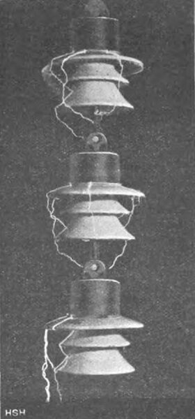
The general character of spark discharges on several suspended insulators connected in series can be seen in Fig. 22, which shows three insulators being tested at 165,000 V under lateral rain. In contrast, on insulators with a smooth disc or plate shape, as mentioned, the spark discharges mostly slide along the surface.
One special feature of the discharge phenomena of all hanging insulators should also be mentioned: the path of the water threads falling from the casings and the spark discharges that sometimes follow them. The raindrops falling from the upper hanging insulators experience a much stronger outward repulsion than is the case with the lowest insulators. The consequence of this is that the level of the flashover voltage on an insulator is not quite the same in relation to the different spark path length caused by the different direction of the water threads.
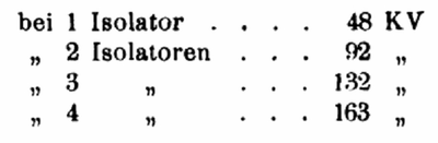
This is also one of the reasons why, when the number of suspended insulators connected in series increases, the total flashover voltage does not increase exactly in proportion to the number of insulators. For example, when different, identical insulators are connected in series, similar to Fig. 8 (p. 598), the following voltages were measured during spark transfer in the rain:
 |
Different in the dry state; here the corresponding values were the following:
 |
| |||
| Fig. 23. Various Designs of Suspended Insulators, Manufactured Among Others by the Porcelain Factory Hermsdorf, S.-A. |
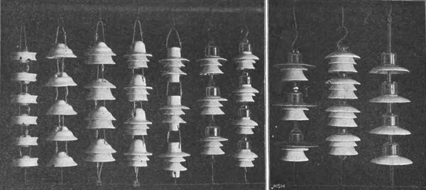
So here there is a voltage increase that corresponds almost exactly to the number of insulators. In order to compare the different types of hanging insulators quantitatively after this general characterization, the selected basic forms shown in Fig. 23 are compared for comparison. It should be mentioned from the outset that the insulators shown are not electrically equivalent, i.e. the different insulator groups cannot be used for the same operating voltages. This only applies approximately to insulator groups 5, 6, 7 and 8. The following list serves as a comparison:
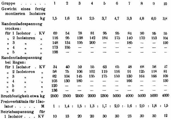 |
The following should be noted regarding the individual columns of the table: The weight and the price refer to a complete individual insulator, so for example in the case of insulators with cap and support they include these, and for the others the required wire rope and lock.
The mechanical strength is the approximate average value from a large number of individual determinations.
The edge discharge voltage in the case of rain refers to a rain force of around 2 mm per minute with impact coming obliquely from above. The spark voltage values given apply to the arrangement shown in the photographic figure 23. In this case, the spark over for some insulator groups did not occur across each individual insulator from connecting link to connecting link, but from the upper bracket or cap across all insulators together to the respective lowest electrode. In general, preference will be given to such a compact insulator arrangement, which offers the advantage of a smaller distance between the conductor wire and the suspension point and thus the possibility of a lower mast height, despite the lower overall flashover voltage, since it is then easier to equalize the charge along the insulators when overvoltages occur, without particularly endangering the insulator. This is relatively easy to achieve with metal roof insulators according to Group 8, where the individual elements are particularly close together and the sheet metal jacket is large in relation to the height of the insulator, so that the spark discharges can be safely carried out from metal jacket to metal jacket, bypassing the insulator.
If, however, the insulators are arranged so far apart that the spark discharges always have to occur around each individual insulator, the voltage values are sometimes significantly higher. For example, for:
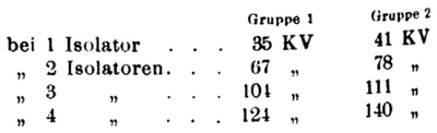 |
In addition to the direct spark transfer, the behavior of the insulator with respect to the pre-discharges preceding the actual spark plays a special role; the latter have been observed not only in rain, but also in dense fog and simultaneous, light rain.
The individual insulator types differ quite significantly in this respect, as was already pointed out above in the general overview. The operating voltage values given in the last column were determined primarily with this circumstance in mind, but these should of course only be regarded as approximate or only comparatively valid. Also, according to the comments made above, when several insulators are connected in series, the permissible operating voltage is not entirely proportional to the number of insulators, but should be assumed to be somewhat lower. For example, insulator groups no. 5, 6, 7 and 8 are each suitable for an operating voltage of around 80,000 V. The support insulator shown in Fig. 21, which shows the same insulator group 6, can, for example, only be used for about 75,000 V. (For the price ratio of the two insulators, see Fig. 20.)
In addition to the downward-hanging arrangement of the insulators discussed so far, a horizontal arrangement can also be considered for guying purposes in curves, and the question is which shape of insulator is best suited for this. From the tests carried out on this, it should be mentioned that in this position there is of course a significant reduction in the insulating capacity of the insulators, so that it is advisable to connect a larger number of insulators in series for the same voltage.
In addition to observing the discharge phenomena, the energy loss caused by surface conduction was also determined for the various insulator shapes, again for rain, as well as for dense fog and rain. These measurements showed that the very low energy losses for bell-shaped and disc-shaped insulators in a hanging or standing arrangement increased significantly in a horizontal arrangement.
For this reason, support insulators for wire bracing in curves should retain their full justification. In contrast, bracing insulators as shown in Fig. 21 (p. 599) are completely unsuitable for this purpose.
To give some comparative figures, it should be mentioned that under the extremely unfavourable conditions given at 80,000 V voltage between the suspension point and the conductor wire, hanging insulators with discharging sheaths for each insulator group of several elements hanging vertically produced around 20 watts, whereas horizontally 100 to 150 watts (insulators according to Fig. 18 and 21 (p. 599) even produced several times this amount), while an upright supporting insulator for the same operating voltage showed only about half as much power loss (80 to 100 watts).
| |||
| Fig. 24 Simultaneous Mechanical and Electrical Testing of Two Suspension Insulators Under 3400 Kg Load and 5000 V Voltage. |
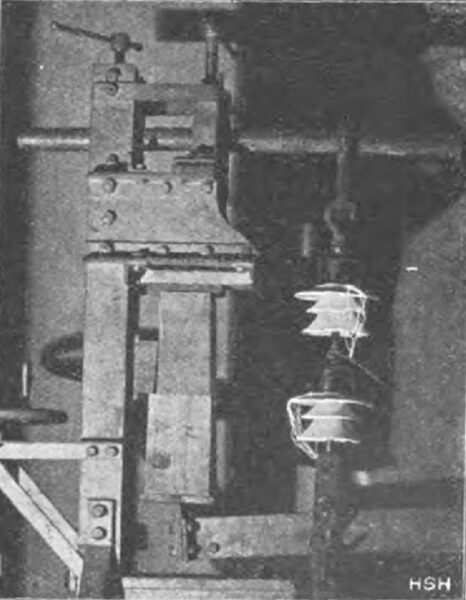
Finally, the question should be touched upon as to whether the operational reliability of an insulator that is subjected to both mechanical and electrical stress, as is the case with tension insulators, is reduced by a reduction in its strength. For this purpose, as shown in Fig. 24, two suspended insulators, mechanically connected one behind the other and electrically connected in parallel, were loaded with a load of up to 3000 kg and voltage was applied between the two insulators and the earthed loading device. It was found that up to the edge discharge voltage (in this case 80,000V) no breakage or breakdown of the insulator occurred, even after a longer test period. Similar tests were also carried out with other insulator shapes and in no case was it proven with certainty that there was a detrimental effect of simultaneous electrical and mechanical stress.
In the case of the insulators shown in Fig. 7 (p. 597), the test was also carried out in such a way that water was frozen in the upper opening at very low temperatures and the insulator, which was thus under natural pressure from the inside, was tested outside. In this case, too, no reduction in the breakdown voltage could be determined. At the same time, the remarkable result was that the insulator did not burst apart due to the ice, but rather always escaped outwards in the slightly conical hole. In any case, if the durability of an insulator is adversely affected by the simultaneous effect of electrical and mechanical stress, this influence is so insignificant that it can hardly be taken into account in practical conditions.
Summary.
The various types of hanging insulators are compiled according to their development and construction, and then comparative general information is given regarding manufacturing difficulties, mechanical and stress, breakdown strength, safety against edge discharges in the rain. Furthermore, comparative price and weight curves for hanging insulators compared to support insulators are given, from which the superiority of hanging insulators is evident, especially for higher voltages. Finally, based on various designs of insulators from the Hermsdorf S.-A. porcelain factory, numerical information is also given on the mechanical and electrical strength (the question of operational safety under simultaneous mechanical and electrical stress is also addressed), weights, flashover voltage and losses.
