[Trade Journal]
Publication: Electrical World
New York, NY, United States
vol. 55, no. 20, p. 1294-1298, col. 1-2
TRANSMISSION INSULATORS.
Detailed Comparison of High-Tension Insulators of
American and European Design.
BY A. S. WATTS
THAT the subject of transmission insulators is one of utmost importance to the electrical world is without denial. That a thoroughly practical and successful transmission insulator is not as yet on the market is yearly, almost monthly, evidenced by the attempts on the part of engineers of all classes to produce a new and superior insulator design or combination. All such designs are of interest to the insulator-producing and using world, since it can only hope thus ultimately to reach perfection. As to the practicability of manufacture and operation of the majority of the designs offered, production and use have proven their faults in such a convincing manner that it seems useless to occupy a great deal of space with the renumeration of the sorrows which have resulted from errors on the part of both designer and manufacturer.
The designing of transmission insulators has been almost entirely in the hands of electrical engineers. Most of these men have studied the demands of the operating line, but since the manufacture of insulators is not in any way associated with the training of engineers for electrical transmission work, the result of their designs and demands is often startling. Moreover, the design of many an insulator has been undertaken with all the available data at hand and with all due consideration for the difficulties arising both in manufacture and operation, and yet this same insulator, for some unforeseen reason, failed to possess the insulating value possessed by other insulators of even smaller dimensions. It is too late, however, when an insulator is manufactured and installed, to do more than profit by the lesson taught. Yet, when it is realized that practically all the problems of high-tension transmission have developed in the past decade, the progress is not by any means discouraging. It must also be borne in mind that the investigation of power transmission insulation problems is not die simple matter that one finds in the study of most electrical problems. The development of electrical machinery has gone forward under the guidance of great companies with almost unlimited capital. Enormous sums of money have been expended in building and testing apparatus of all sorts and designs, a great portion of which proved worthless. On the other hand, the history of insulator development reads much as follows : The engineer in charge waits until about go days before he must have the insulators on the poles and then starts a canvass of past designs and a gathering together of his personal ideas of how an insulator should be constructed in order to be of the greatest efficiency. The result is a new design, on which bids are received and to the lowest bidder goes the contract. Then comes the delay due to the redesigning of the insulator in order that it may be manufactured. This delay is naturally annoying to the engineer, who cannot, as a rule, see the necessity of the changes proposed and he is further displeased at the time lost in beginning manufacture. The real annoyance begins, however, when the line is completed, the insulators are in place, the wire strung and the e.m.f. applied. Every engineer knows how many lines have never been operated at the voltage for which they were designed. A few have been raised from the original voltage without change of insulators, but many more have settled down to work at from 10 to 20 per cent less than the designed voltage. And in nearly every case the fault was in the insulator, either in design, construction or composition. By these repeated failures it is beginning to be generally realized that not enough preliminary research has been carried on in the matter of insulator design. And still, when an engineer designs an insulator, he hesitates to submit it to a manufacturer and have a test quantity made because of the expense connected with such a process. Instead, he waits until called upon for an insulator for immediate service, and rushes his untried idea into the field with results as above noted. Many electrical engineers may say in self-defense that they have been forced to design their ill-fated insulators because the manufacturer offered nothing that met their requirements. This is possibly in a measure true, but if one manufacturer went to the expense of making, in sufficient quantity for test, new designs of every sort and shape offered, he would expend yearly not only his meager profits, but also a portion of his working capital. On the side of the manufacturer, it may also be said that he should be, and generally is, conservative in his insulator designs. His design must come up to his guarantee in every respect, otherwise he is expected to replace them and sacrifice more than his profit. This has happened in a few instances and has undoubtedly created an undue amount of caution on the part of manufacturers. Furthermore, the patenting of any principle or design by the manufacturer has oftener proven a source of expense than of profit. The idea is slightly changed, bids are called for and the lowest bidder, whether he be the originator or not, gets the business. To bring suit against the competing manufacturer means that the engineer who let the contract will be angered and the patentee-manufacturer cannot hope for any of his future business. Such a condition is ruinous to the manufacturer.
If the development of high-tension insulators is to continue as in the past in the hands of the electrical transmission engineer, it seems highly important that he possess some reliable comparable data upon the relative values of the various insulators now in use, in order, not only to be able to select from those now available, but also to place an intelligent value upon any new design presented for his approval. At the present time such data is so meager that it is practically worthless. In tests made by engineers the data are generally so incomplete that the engineer has little more of value than might have been obtained from a common sense study of the designs tested. This is especially apparent when an attempt is made to repeat tests with other than the equipment with which the original tests were made.
German engineers have, probably, given more attention to uniformity of tests and a careful analysis of the results, but even here the data are very scarce and incomplete. However, when the development of the high-potential insulator is considered Americans may justly feel proud of the progress made in the United States as compared with the progress made in Europe along this line.
AMERICAN INSULATORS.
It hardly seems necessary to repeat the history of insulator development in the United States. However, for the purpose of comparison it may be advisable to refer to some of the characteristic types. In order to facilitate comparison all illustrations of insulators are reproduced to the same scale. Scarcely so years ago the first genuine high-tension insulator was offered for sale in the United States. Its construction was similar to the type shown in Fig. 1.
 |
| Figs. 1-6 — Chronological Development of American High-Tension Insulators. |
This insulator consisted of a porcelain head and intermediate shell manufactured separately and fused together during the burning process by means of a layer of glaze. With these was used a glass center which was attached to the other parts by means of Portland cement. This insulator did not prove all that was hoped for, but it was a great advance over the simple bell insulator which had been used up to this time and which was still in service in Europe.
The next step in insulator development was the lengthening of the intermediate shell and the introduction of a narrow flange on the under side of the top shell in order to lengthen the bearing surface between the top and second shells which were now united by use of Portland cement, as the glaze joint proved unreliable when subjected to great strains or sudden changes of temperature. The center was also now made of porcelain, thus eliminating the use of the glass, which caused trouble on account of its brittleness.
The next step was the extending of the head portion sufficiently to permit of the introduction of a fourth shell. This type is illustrated in Fig. 2.
Up to this time the development of the insulator consisted merely in the expansion of the original type, thus furnishing greater striking and leakage distances. The only variation in this type had been to make the intermediate and inner shells in some instances slightly concaved to the weather, thus increasing the striking distance between the rim of each shell and the opposite surface of the next cell. This slightly increased the striking distance and also was a material advantage in manufacture, as it was found that when a long straight surface was made, there was a tendency for the clay mass to crowd to the rim of the mold without properly packing the intermediate portion. This tendency was overcome by the retarding action of the curved surface of the mold. Insulators like that shown in Fig. 2 proved very successful from the point of manufacture and also for employment on transmissions up to 60,000 volts, provided the operating conditions were good. If the conditions were severe or an addition of 6000 volts was considered, the mere increase of dimensions failed to give satisfactory results.
The result was a series of insulators varying considerably in form and possessing properties peculiar to themselves. In this class are the insulators illustrated in Figs. 3, 4, 5 and 6. The insulator shown in Fig. 3 was designed with the idea that, by having two large shells close together, one would obtain two surfaces to which the rain could not gain access and thus a notably increased efficiency under storm conditions was expected. The result, however, was that insects and dust collected in this protected place where the wind could not dislodge them, and this proved a conductor equal to the film of moisture accumulating during a storm. The proper cleaning of such an insulator also proved very difficult because of the narrow opening. In the manufacture much difficulty was encountered on account of the head, which was made very flat with abruptly turning rim. In the firing process this displayed a tendency to warp so that a valley was formed next to the tie-wire groove in which a small amount of water or dust could lodge. The very long straight inner shells proved also difficult to make successfully for reasons above noted.
Fig. 4 represents an insulator of almost the same dimensions as that in Fig. 3, but proving much superior both as regards operating efficiency and success of manufacture. This type has the peculiarity of having only convex surfaces exposed to the weather. If the rain comes from an angle less than 45 deg. to the vertical, the drops of water are inclined to glance down and off rather than up onto the overhanging shell. This insulator was never put into service in the United States, although many thousands were made and sent to Japan, where they proved very successful. This insulator presented no great difficulties in manufacture aside from such as must invariably arise from the handling of large pieces of porcelain.
Fig. 5 represents an elongated specimen of the type shown in Fig. 2 and had previously been extensively employed for 45,000-volt lines. This insulator was manufactured and employed only as a three-part insulator, the pin being cemented directly to the longest shell, which served also as center. Its failure when employed for high voltages lay in the fact that when put to the strain which its size seemed to warrant, it proved unequally balanced, causing the center to puncture during the stress of storm service. This difficulty was overcome by expanding the various dimensions sufficiently to permit of the introduction of a fourth shell, as here shown, thus placing two thicknesses of porcelain between the steel supporting pin and the first exposed surface. However, when thus redesigned, this type proved so heavy and so expensive to produce that it was never put into use. Regarding the manufacture of this insulator it is almost needless to say that the long straight surfaces presented great difficulties and the enormous losses in test were only indicators pointing to its ill fate when put into actual service.
In Fig. 6 is shown the Fig. 2 type expanded instead of elongated. This type proved very successful for voltages up to 75,000, but, like Fig. 5, the cost of production and the expense of installing such heavy insulators is in most cases not justified by the additional efficiency obtained. In the manufacture of such an enormous extending head as this insulator possesses much difficulty was naturally experienced on account of warping during the firing process. The most important fact brought out by the development of these large insulators is that an insulator of the type and size of Fig. 3 possesses so nearly equal value in service to that possessed by the larger types. When the enormously increased cost and the small increase in efficiency to be obtained by increasing the size of insulators past a certain point came to be known, there was a tendency to abandon these large types and return to more moderate sizes.
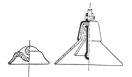
In the United States, as in Europe, the underhanging insulator came as a result of the discovery that for proposed 100,000-volt lines no pin-type insulator could be successfully employed. Various types of underhung or suspended insulators have since been offered, each having its peculiar advantages, as well as its disadvantages. In the design of an underhung insulator it is generally agreed that it must be so constructed that in case the insulator is destroyed, the line will not drop. Of the insulators so constructed, the best known types are the Hewlett insulator, Fig. 7, and the Duncan insulator, Fig. 8.
 |
| Figs. 7 and 8 - Underhanging Insulators. |
In the type illustrated in Fig. 7 the supporting cable passes into the porcelain, below and through, the loop which supports the next lower insulator or the transmission line. Thus there are two intersecting loops which certainly furnish absolute security against the dropping of the line. On the other hand, there is an opening in the top of the insulator into which water may enter and render the insulator liable to bursting by frost unless the curved hole is so bored that it tapers from each opening to the middle. As regards the manufacture of this insulator the author cannot speak with much authority, since he has had to do with the manufacture of only a comparatively small number. However, the problem of boring a curved hole in an unburned mass of porcelain is certain to be not only a very difficult but a very uncertain task. Being unable to see through the holes, one can never be certain that fine cracks or flaws do not exist and the result is that all apparently good insulators must go to the kiln and be burned and tested before one can determine the proportion of rejection. The cost of burning a considerable number of worthless insulators must naturally add to the cost of the good insulators produced, since the insulators sold must bear the total cost of production.
Of the type illustrated in Fig. 8 the author's personal observation in connection with the manufacture of many thousand has convinced him that with the porcelain under compression as it is here, it is impossible to pull the bolt out of the cap with any amount of load which could be introduced by means of snow or ice added to the cable. In fact, the cable would itself part long before the strain on the insulator became enough to cause rupture. As to the problems of manufacture it may be said that the manufacture of this insulator does not present any problems other than would naturally be expected in an insulator with a small head and which is to be subjected to an excessive test and working strain. The Swedish engineer, Olav Ingeborg, in Norkopping, who is transmitting 200 hp at 500,000 volts for use in his research laboratories, has recently equipped his line with this type of insulators exclusively after testing out practically all types. So much for American insulators.
EUROPEAN INSULATORS.
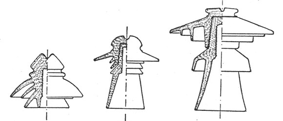
The development of transmission insulators in Europe has been along very different lines, although the original type employed was very like that first used for lower voltages in the United States. While, in Europe, much larger single pieces of porcelain are produced than in the United States, the demand for transmission insulators for voltages above 50,000 has been comparatively small. In fact, there is only one transmission line in Germany operating at more than 40,000 volts, that being the Moosburg-Munich line operating at 50,000 volts and delivering 4000 kw power. The only transmission lines in Europe operating at above 50,000 volts are: D'Orlo Toulouse, in France, operating at 55,000 volts; the Montiers-Lyon line, also in France, transmitting 4100 kw at 57,000 volts; and the Espanola-Madrid line, reported to be now operating at 66,000 volts. In none of these transmissions have they been forced to resort to insulators of extreme dimensions, so that there is little opportunity for comparison. Regarding insulator development in Europe, the Hermsdorf Parzellanfabrik patented in 1897 the "delta glocke" insulator, Fig. 9.
 |
| Figs. 9, 10 and 11 - German Insulators. |
This type of insulator has been produced in all sizes up to about 12 in. diameter and throughout Europe is undoubtedly the most extensively employed type for moderate voltages. Of its merits much will be said later. It has the peculiarity of having only one thickness of porcelain between the line and the pin. In the manufacture of insulators in the United States this has been considered unreliable. Furthermore, with American materials, the production of large single piece insulators has not been successful. In Germany such insulators are produced by two different methods. One is to form a mass of body large enough to permit the bells to be turned out of the mass on a lathe while still in the half-plastic condition. The other is to make the bells separately and attach them while still plastic to the body portion of the insulator. This latter process is employed for the larger insulators and one rarely finds a German insulator that has punctured through the joint. Such joints have been attempted a number of times on insulators in the United States, but always without success. The author is convinced that the European clays lend themselves much more readily to this process than do American clays.
Another insulator used extensively in Europe is illustrated in Fig. 10. This type, known as the "rillen" insulator, depends upon the principle of having a number of "rillen" or grooves cut into the body shell at a point well up on the body shell so that they are protected from most direct rain by the overhanging head of the insulator. The value of a number of these insignificant grooves is remarkable. The Ph. Rosenthal Company, who produced this insulator, have developed it for higher voltages into the insulator shown in Fig. 11. This insulator is said to be serviceable for voltages up to and including 66,000 volts. In its manufacture the projecting flanges are all made separately and joined in the green condition to the body portion of the insulator. The production of this type of insulator was attempted in the United States some years ago, but was abandoned on account of the difficulties of manufacture.
 |
| Fig. 12 - Kuhlmann Insulator. |
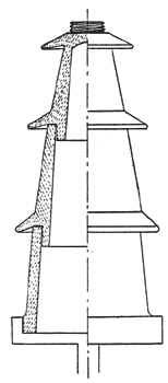
Another insulator design, the uniqueness of which makes it worthy of attention, is shown in Fig. 12. This design was offered by Karl Kuhlmann, and is in substance the same idea as was suggested by an American engineer two or three years ago. This insulator would naturally fall in the same class as Figs. 5 and 6, since its enormous size would make its production and installation exceedingly expensive if not prohibitive.
 |
| Figs. 13, 14 and 15 - Suspension Insulators. |
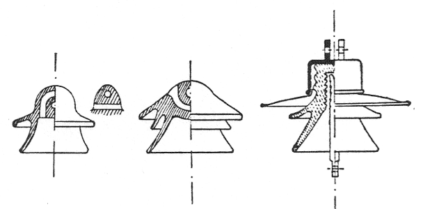
In Germany, the Hermsdorf Porzellanfabrik have placed on the market a large variety of underhung insulators. The ones most highly recommended are of the types shown in Figs. 13, 14 and 15. Figs. 13 and 54 may be properly classed with the American type shown in Fig. 7. Fig. 13, however, has a straight hole for the upper loop which overcomes the danger of water collecting in this exposed opening. It also has the advantage of an extending shell which, of course, materially increases its efficiency.
Fig. 14 is practically the same as Fig. 7 in principle, but has incorporated as nearly as possible the type of the old delta glocke in an underhung insulator. That the type here also retains its value is indicated by a report of tests made by W. Weicker under the same rain and test conditions and with insulators of the same diameter:
 |
The European underhung insulator which most nearly resembles Fig. 8 is shown in Fig. 15.
This insulator is notable on account of having a thin enameled sheet-steel umbrella in place of the first porcelain shell While the value of the insulator when dry is thus slightly reduced, its value under rain is increased, since with enameled steel a flatter, wider umbrella can be made than with an equal weight of porcelain. Under the same rain test conditions as above Weicker found this insulator to possess the following values:
 |
COMPARISON OF EUROPEAN AND AMERICAN INSULATORS.
Any attempt to compare, from the data available, the relative efficiency of European and American insulators would be not only worthless, but probably very misleading, except in cases where the tests were made at the same time and place and with the same testing equipment.
Friese in writing of high-voltage insulators figured the efficiency on the basis of the formula:
 |
As an example he compared a Hermsdorf delta glocke insulator and an American insulator tested under the same conditions and having practically the same value for A. The results of these tests are as follows:
 |
Thus, a delta glocke insulator of approximately 7 in. diameter by 7 3/4 in. high and weighing 4.7 lb. was shown to have an insulating value equal to that possessed by an American insulator of 8 in. diameter by 9 in. high and weighing 6.4 lb.
These figures prove beyond dispute the high efficiency of the delta glocke type of insulator and this is further confirmed by the remarkably high value of the underhung insulator (Fig. 14) designed after this model.
Despite these figures the European engineers have followed the American example in the design of insulators for higher voltages and have increased the size with more than a proportionate increase in weight.
On both sides of the ocean this has resulted in the discovery that size alone does not produce efficiency in an insulator, but that the volume of porcelain contained therein and the amount of surface as compared with the weight of the mass bear a definite relation to the efficiency of the insulator produced.
 |
| Fig. 16 - Dielectric Strength of Porcelain. |
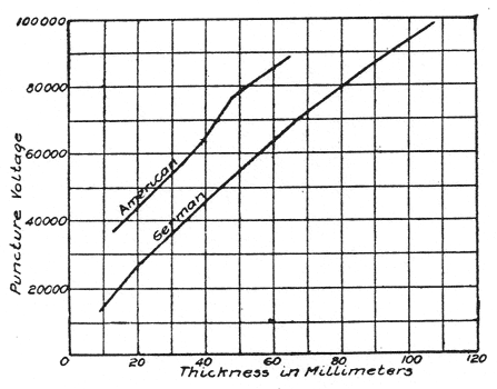
That the insulating efficiency of a porcelain mass does not increase in direct ratio with its thickness has been known to insulation engineers for several years. Researches which the writer is pursuing, upon the insulating value of porcelains from European materials, are not as yet in shape for publication, but herewith are given, in Fig. 16, the most recently published curve showing puncture voltages of various thicknesses of German porcelains. On the same plate is shown a curve of puncture voltages for various thicknesses of American porcelains. While the two curves were not made under the same test 'conditions and therefore the actual values therein contained cannot be compared, yet it is interesting to note the fact that the curves run practically parallel, which indicates that the influence of thickness upon insulating value is the same for European as for American porcelains.
 |
| Fig. 17 - Relation Between Test and Working E.M.F. |
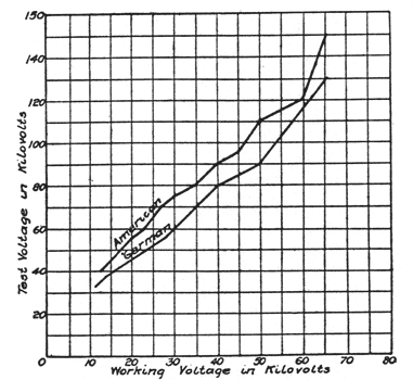
The idea prevails in the United States that German products are prepared to stand a higher test than American insulators. While the writer is not prepared to say that they will not stand an equal or even greater relative test than the American insulator, the fact remains that, based upon the relation of test voltage to working voltage, the German insulator is not ordinarily as severely tested as the American insulator. This is graphically shown in the accompanying curves, Fig. 17.
At no point does the German insulator bear as great a relative test as does the American insulator. In fact, the Verband Deutscher Elektrotechniker specifies a much more moderate test as follows:
For working voltages up to 5000 volts the test is double the working voltage.
For working voltages up to 5000 to 10,000 volts the test is 5000 volts above working voltage.
For working voltages above 10,000 volts the test is 1.5 X the working voltage.
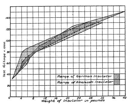
These lower test voltages and the above data offered by Friese regarding the delta glocke insulator are probably responsible for the impression which prevails throughout both Europe and America that the German insulator is uniformly lighter for a given working voltage than the American insulator. While the delta glocke, and, in fact, all the smaller German insulators, including the rillen type, are relatively lighter than the American insulators, when the weight is compared with the test voltage instead of working voltage, it is found that the insulators of both lands fall within the same area. The writer has collected all the insulator weights available, numbering several hundred, and these are presented in Fig. 18, showing the areas covered by American and German insulators when weight is compared with test voltage, which is generally assumed to mean the actual capacity of the insulator or nearly so.
Thus it is seen that engineers, both in Europe and America, have reached the same point and can go no farther. They have proven only that a larger insulator does not possess proportionately increased efficiency. The possible reasons for this peculiar phenomenon the writer will attempt to discuss from the viewpoint of a porcelain chemist at another time.
In the study of insulators it may be said that all transmission insulators may be divided into two classes.
Class A.—Those constructed with the idea that they shall possess enough dry surface at all times to provide the necessary insulation.
Class B.—Those constructed upon the principle that porcelain surfaces, even when damp, possess a certain insulating value and if enough distance is provided the required insulation is secured.
The fault with class A is that it is practically impossible to prevent some rain from spattering from the exposed surfaces up and onto the protected surfaces of the overhanging shell. This small amount of water is volatilized by surface leakage and forms steam which rises and hence remains under the overhanging shells of the insulator which protect it from removal by wind. If the rain is of any great duration, this accumulation of steam and vapor reduces the insulating value of the so-called dry surfaces to that of exposed surfaces of porcelain. If the insulator is selected with a sufficient factor of safety the sum of the insulating values of these wet surfaces, plus the insulating value of the inside surface of the center, which generally remains dry, since no spattering can reach it, furnish sufficient insulation to prevent interference with service.
All the types illustrated belong in this class, with the exception of Fig. 12, which plainly belong to class B.
The fault with class B is that it requires so long a surface that the weight, if designed, as here shown, is almost prohibitive, and yet the principle of class B provides the only certain means of insulation.
The principles of these two classes may be combined to produce a reasonably light, efficient insulator, and the writer believes that the solution of the insulator problem for voltages between 60,000 and 100,000 volts is along the following line:
It is known that a plain glazed porcelain tube (class B) 1 ft. long and 3 in. in diameter, when exposed to a rain of 1 in. in five minutes precipitation, possesses an insulating value of about 30,000 volts.
If this same tube is corrugated uniformly its entire length, it is found that its value under the same test is increased to about 50,000 volts.
However, if the tube has undercut corrugations, the surface distance between ends is not only materially increased, but there is some protected surface to aid in insulation. These undercut surfaces not only have the advantage of being small and thus not permitting of any considerable vapor accumulation, but the fact that they are shallow enables the wind to free them of the vapor as fast as it accumulates. This may explain the remarkable value of the rillen in the Rosenthal insulator, Fig. to. Be the explanation of the phenomena what it may, it has been proven beyond dispute that such a corrugated tube, 12 in. long and 3 in. in diameter, under rain test, as above, possess a value of about 100,000 volts. Moreover, a tube being of uniform surface design, the value may be increased by merely increasing the length of the tube.
 |
| Fig. 18 - Weight of Insulators. |
 |
| Fig. 19 - Suggested Type. |
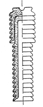
By the employment of the above data the writer offers the insulator shown in Fig. 19. The advantages of such an insulator are many. It is not so heavy as the ordinary 60,000-volt insulator. It can be handled with much less danger of breakage in construction and when in place is practically safe against destruction by miscreants. In case of lightning it has no extending shells to be broken by the shock. The temporary short-circuit passes along its face rather than follow the small corrugations, with the result that it passes such a shock uninjured, whereas with the ordinary shell insulator destruction is certain. In the case of rain its exposed surface is small as compared with most 60,000-volt insulators, hence if it is necessary to keep the protected surfaces absolutely dry by surface leakage, the loss will be comparatively small. The only drawback to such an insulator is the difficulty of manufacture. However, such tubes are made with comparatively little loss in Europe, hence it may be assumed that a little experience would enable the American manufacturer to produce them with equal success. The design presents no difficulty which could be influenced by materials, as is the case where the parts must be made separately and united before burning.
In closing, the writer desires to call attention to what in his opinion is the greatest hindrance to progress in insulator development and which has caused more false impressions and trouble than all other causes combined. Reference is made to the absolute absence of anything like a uniform test for transmission insulators. Voltage and precipitation are spoken of as though they were standard factors not capable of influence by any varying condition. A given voltage may refer to a test with an equipment of 10-kw rating giving a spark like the striking of a match or it may refer to a test with a 1000-kw equipment giving a spark like the explosion of a bomb.
A given precipitation may refer to a fine driving mist or it may refer to a gentle downpour. And so with all the other data that are recorded on insulator tests.
The requirements for a standard test need not be such as to make its employment burdensome. It would be far better to have all tests with moderate equipment of a given type under standard specifications and thus have all data comparable, than to have such an accumulation of odds and ends as is being gathered under the present system. And, moreover, it is not at all in keeping with the progress in other branches of electrical engineering that the American engineer shall continue unable to interpret the results of another engineer's research, because of lack of complete details or because of non-uniformity of testing equipment. If the American transmission engineers would take up this matter with the insulator manufacturers the writer feels certain that they would find willing co-operation and that in a surprisingly short time a set of data which would be of inestimable value to the electrical world would be accumulated.
